Page 209 of 244

@ For the sake of the environment
Used sealant bottles can be dropped off at
a recycling facility .
@ Tips
-If sealant has run out, allow it to dry.
Then you can peel it off.
- Have the tire sealant replaced every 4
years at a dealership .
Preliminary steps
Applies to vehicles: with Tire Mobil ity System
Some preliminary steps are necessary for tire
repair.
Fig. 151 Luggage co mpa rt ment : Tir e Mobil ity System
1> Jf you have a flat tire, park the veh icle as far
as possible from mov ing traffic .
.,. Apply the
parking brak e firmly .
.,. Move the
se le ctor l ever to the P po sit ion .
.,. Check whether a repa ir using the Tire Mob ili
ty System is possible ¢
page 206, General
and safety poin ters .
.,. Have all passengers leave the vehicle and
stay away from the danger zone ¢
A.
.,. Take the se alant bottle and the ele ctri c air
pump
from the luggage compartment un
der the floor¢
fig. 15 l .
.,. Remove the "max. 50 mph" (80 km/h) stick
er from the sealant bottle and aff ix it to the
inst rument cluste r in the driver's v iew .
..&, WARNING
-Turn the ha zard flashers on and set up
th e war ning t ria ng le if you have a fla t
t ire in moving t raff ic. In this way you p ro
tect yo urself and other road users .
-
What do I do now ? 207
-Make sure that all passengers are in a
safe place, out of the danger zone (for
example, behind a guard rail).
(D Note
Particular care is necessary if you are mak
ing a tire repair on a steep incline.
(D Tips
Obey all laws.
Making a tire repair
Applies to vehicles : wit h Tire Mob ility System
Tire repair consists of the following sec tion s.
Fi g. 1 52 Parts of t he T ire Mobility System
Fi g. 1 53 Connector for th e Tire Mob ility System
Assembling Ti re Mobility System
.,. Open the lid @of the electr ic air p ump
¢ fig. 152 .
.,. Pull the plug@) and the pressure hose®
w ith the gauge out of the housing .
.,. Screw the pressure hose® of the e lectric
air pump onto the flange ® of the sealant
bott le @ .
.,. Push the sealant bott le w ith the flange
down into the recess @ on th e lid of th e
elec tric air pump.
IJ,-
Page 210 of 244
 onto the valve
(J)
¢fig . 153.
• Insert the plug@¢ fig. 152 int")
208 What do I do now?
• Remove the dust cap from the valve of the
defective tire.
• Screw the hose@) onto the valve
(J)
¢fig . 153.
• Insert the plug@¢ fig. 152 into the socket
for the cigarette lighter.
• Switch on the ignition .
Inflating tire
• Move the switch@¢ fig. 153 on the e lec
tric air pump
l ) to position I. After 5 mi
nutes, tire pressure must have reached at
least 1.8 bar .
• Switch the electric air pump off -switch in
pos it ion
0 . If the requ ired tire pressure of at
least 1.8 bar has not been reached, follow
the instructions in the section
Re-inflating
tire.
Re -inflating tire
• Remove the hose from the valve and pull the
plug out of the socket.
• Drive the vehicle slow ly 10 meters backward
or forward. This helps to distribute the seal
ant better .
• Remove the empty inflation bott le and
screw the hose®¢
fig. 152 from the elec
tric pump directly onto the valve.
• Insert the plug@¢
fig. 152 into the socket
for the cigarette lighter.
• Switch on the ignition .
• Move the switch @¢
fig. 153 on the e lec
t ric air pump
l) to posit ion I. After 5 mi
nutes, tire pressure must have reached at
least 1.8 bar.
• Switch the electric air pump off -switch in
position
0. If the required tire pressure of at
l east 1.8 bar has not been reached, it is not
poss ible to make a repair with the tire seal
ant. Seek professional ass istance.
Disassembling Tire Mobility System
• Remove the hose from the valve and pull the
plug out of the socket.
• Screw the dust cap onto the va lve.
1l The electric air p ump sho uld never ru n fo r long er than
6 min utes.
• Place the empty sea lant bott le back in the
original packaging and clip it in place under
the floor so that no t ire sea lant can run out
into the veh icle.
• Place the electric air pump in the luggage
compartment for the t ime being .
• Start driv ing right away so that the sealant
is distributed in the tire.
_&. WARNING
- Follow the manufacturer's safety instruc
tions on the decal for the air pump and
the sealan t bottle.
- If a tire pressure of 1.8 bar cannot be
achieved after pumping for 5 minutes,
the tire is too severe ly damaged. Do not
continue to drive.
- Seek professional assistance if it is not
possible to repair the tire with the tire
sealant.
(D Tips
- Do not operate the electric air pump for
more than 6 minutes without stopping,
otherwise it can overheat . When the air
pump has cooled down, you can continue
to use it.
- If sea lant has escaped, allow it to dry,
then you can pee l it off.
Final check
App lies to vehicles: wit h Tire Mobility System
After driving for a short distance, tire
pressure must be checked
• After driving for about 10 minutes, stop and
check the tire pressure .
• If tire pressure is still at least 1.3 bar, in
flate the tire to specified pressure (see driv
ers side B-pillar), drive to the next repa ir
shop and have the tire and the sealant bot
tle replaced.
• If tire pressure is less than 1.3 bar, the tire
is too severely damaged. Do not continue to
drive . Seek professional assistance. .,.
Page 211 of 244

A WARNING
If tire pressure is less than 1.3 bar after
driving for 10 minutes, the tire is too se
vere ly damaged . Do not continue to drive .
Seek p rofessional assistance.
@ Tips
After a tire repair, have the sealant bottle
rep laced at a dealership . This restores full
functionality to the Tire Mob ility System .
What should I be
aware of when
changing a tire?
General information
The fo llow ing se ctions wi ll provide yo u wit h
importa nt information on how to change a
tire using the vehicle too l kit .
H oweve r, we recomme nd that you have a
q ua lified servi ce center cha nge the tire and
perform all wo rk associa ted with changing it.
Wheels with cap-covered wheel bolts
Applies to vehicles: with cap-covered wheel bolts
The caps must be removed first from the
wheel bolts before the bol ts can be un
screwed .
Fig. 154 Wheel c hang e: remov ing the whee l bo lt caps
Rem oving
.,. Push the plastic clip provided w it h the on
board tool kit down over the whee l bolt cap
until it engages .
.,. Pull on the properly engaged
plastic clip to
extract the cap
c> fig . 154.
What do I d o now ? 209
Refitting
.,. Place the caps over t he whee l bolts and
push them back in.
T he caps are t here to protect and keep the
whee l bolts clean .
Decorative wheel covers
App lies to vehicles: wi th deco rative w heel covers
Th e decorative whe el covers must be removed
firs t to ac cess the wheel bolt s.
Fi g. 1 55 Wheel change: remov ing the w heel cover
Removing
.,. Insert the hook provided with the on board
too l kit into the hole o n the center hub
piece.
.,. Pull off the
decorative wheel cover
<=>fig. 155.
Loosening and tightening the wheel
bolts
The wheel bolts must be loosened before rais
ing the vehicle .
Fig. 1 56 Wheel cha nge: loosen ing the wheel bolts
Loosening
.,. Fit the wheel bolt wren ch over the whee l
bolt and push i t down as far as it will go .
Page 212 of 244

210 What do I do now?
• Close your grip around the end of the
wrench handle for maximum torque and
turn the wheel bolts
counter-clockwise
about one single turn in the direction of ar
row
¢ fig. 156.
Tightening
• Fit the wheel bolt wrench over the wheel
bolt and push it down as far as it will go .
• Close your grip around the
end of the
wrench handle for maximum torque and
turn each wheel bolt
clockwise until it sits
t ight.
A WARNING
- Us ing force without control to speed the
wheel change up can cause the veh icle to
slip off the jack and cause serious per
sonal inju ries.
-Do not loosen the wheel bolts more than
one turn
before you raise the vehicle with
the jack. -Risk of injury!
- Never t ry and use the hexagonal socket
in the handle of the screwdriver to loos
en or tighten the wheel bolts.
- If a wheel bolt sits very t ight, you may
find i t eas ier to loosen by carefully push
i ng down on the end of the whee l bolt
wrench with
one foot only. As yo u do,
hold on to the car to keep yourself stable
and take care not to slip .
Raising the vehicle
The vehicle must be lifted with the jack first
before the wheel con be removed .
a
Fig. 157 Sill pa nels : m ar kings
Fig. 158 Sill : posit ioning the vehicle jac k
• Apply the parking brake firmly to prevent
your veh icle from roll ing unintentionally.
• Move the
selector lever to position P .
• Position the jack be low the door sill under
t he
mounting point that is closest to the
wheel to be changed ¢
fig. 157.
• Extend the jack under the lifti ng point on
the door s ill until its arm is positioned di
rectly under the lifting point ¢,&. .
• Align the jack so that its arm®¢
fig. 158
engages in the designated lifting point in
the door s ill and the movable base ® lies
flat on the ground . The base @ must be
ver
tical
under the lifting point@.
• Wind the jack up further unti l the flat tire
comes off the ground ¢
.&,.
Position the vehicle jack only under the desig
nated lifting points on the sill
¢fig . 157.
T he re is exactly one locat ion for eac h wheel.
T he jack must not be positioned at any other
location ¢
.&,¢(D .
An unstable surface under the jack can cause
the vehicle to slip off the jack. Always provide
a firm
base for the jack on the ground. If nec
essary p lace a sturdy board or simi lar support
under the jack. On
hard, slippery surfaces
(such as tiles) use a rubber mat or similar to
prevent the jack from slipping ¢
.&,.
A WARNING
--You or your passengers cou ld be injured
while changing a wheel if you do not fol
low safety precautions:
- Position the vehicle jack on ly at the
designated lifting points and align the
jack. Otherwise, the vehicle jack could
Page 213 of 244

slip and cause an injury if it does not
have sufficient hold on the veh icle.
- A soft or unstable surface under the
jack may cause the vehicle to slip off the jack. Always provide a firm base for
the jack on the ground. If necessary, use a sturdy board under the jack .
- On hard, slippery surface (such as tiles)
use a rubber mat or similar to prevent
the jack from slipping .
- To help prevent injury to yourself and
your passengers:
- Do not raise the vehicle u nti l yo u are
sure the jack is sec urely engaged .
- Pa ssenge rs must not remai n in the ve
h icle when it is jacked up.
- Make sure that passengers wait in a
safe pl ace away from the vehicle and
well away from the roadway and traffic.
- Make sure ja ck position is correc t, ad
just as necessary and then continue to
ra ise the jack .
(D Note
A floor jac k or the pads o n the hoist arms
m ust
n ot be po sit ioned at the po ints
shown
-arrows- .
Taking the wheel off
Follow these instructions step-by-step for
changing the wheel.
Fig . 159 W hee l ch ange : us ing th e sc rewdr ive r hand le
(w ith t he blade re m ove d) to turn t he bo lts
What do I d o now ? 211
Fig . 1 60 W hee l cha nge : alignmen t pin inside the top
ho le
After yo u have loosened all wheel bo lts and
raised the vehicle off the ground, perform the
follow ing steps to remove and replace the
whee l:
Remo ving the wheel
.,. Use the he xagonal socket in the scr ewdri v
er handle
to completely turn out the top
most whee l bolt and set it aside on a
clean
surface ¢ fig. 159.
.,. Screw the threaded end of the alignment
pin
from the tool kit hand-tight into the
now vacant bolt hole¢
fig. 160 .
.,. Then completely unscrew the other wheel
bolts as desc ribed above.
.,. Take off the whee l leaving the alignment pin
in the bo lt ho le ¢ (D.
Putting on th e wheel
.,. Lift the spare wheel and carefully slide it
over the alignment p in to guide it in place
Q (D .
.,. Use the hexagona l socket in the screwd river
handle to screw in and tig hten all whee l
bolts
slightly .
.,. Unscrew the alignment p in and insert and
tighten the remaining wheel bolt slightly like the rest .
.,. Turn the jack handle counter-clockwise to
lower the veh icle until the jack is fully re
leased .
.,. Use the whe el bo lt wrench to tighten all
wheel bo lts fi rm ly
Q page 209 . Tighten
t hem
crosswise, from one bolt to the (ap
proxima tely) opposi te one, to keep t he
wheel cente red.
Page 214 of 244

212 What do I do now?
When removing or installing the wheel,
the rim could hit the brake rotor and dam
age the rotor. Work carefully and have a
second person help you.
Never use the hexagonal socket in the han
dle of the screwdriver to loosen or t ighten
the wheel bolts.
- Pull the reversible b lade from the screw
driver before yo u use the hexagonal
socket in the handle to turn the whee l
bo lts.
- When mounting tires with
unid irectional
tread design
make sure the tread pat
tern is pointed the r ight way
~page 212.
- The wheel bolts should be clea n and easy
to tu rn . Check for d irt and corrosion on
the mat ing su rfaces of both th e whee l
and the h ub. Remove a ll dirt from these
su rfaces before remo unti ng the wheel.
Notes on wheel change
Pl ease read the informa tion ~ page 192, New
tires and replacing tires and wheels,
if you are
going to use a spare t ire which is different
from the tires on your vehicle.
After you change a tire :
-Check the tire pressure on the spare imme
diately after mounting .
- Have the wheel bolt tightening torque
che ck e d with a torqu e wrench a s soon as
possible b y your auth orized Audi dealer or
a qualified ser vice station .
- With steel and alloy wheel rims , the wheel
bolts are correctly tightened at a torque of
90 ft lb (1 20 Nm ).
- If y ou notice while changing a tire that the
wheel bolts are co rroded and difficult to
turn , then the y should be repl aced befo re
you check the t ightening torque . -
Repla ce the flat ti re with a new one and
have it installed on your veh icle a s soon as
possible. Remount the wheel cove r.
Until then , dr ive with extra care and at re
duced speed s.
_& WARNING
-
- If you are going to eq uip your vehicle
wit h tires or rims which differ from those
which were factory installed, then be
sure to read the information
9 page 192,
New tires and replacing tires and
wheels.
- Always store the tools secu rely i n lug
gage compartment. Othe rwise, in a n ac
cident or s udden maneuver they cou ld fly
forwa rd, causi ng injury to passengers in
the vehicle.
Tires with unidirectional tread design
Tires with unidirectional tread design must be
mounted with their tread pattern pointed the
right direction.
A un idirectional tire can be identified by ar
rows on the sid ewall ,
which point in the direc
tion of the rota tion. Yo u m ust follow the
specified direction of rota tion. This is ne ces sa
r y in order fo r these tires to develop t heir op
timum character istics regard ing grip, road
noise, wear, and hydrop laning.
Page 215 of 244

Fuses and bulbs
Electrical fuses
Replacing fuses
Fuses that have blown will have metal strips
that have burned through.
Fig. 161 End face of instrument panel: removing cover
p la te to access fuses
Fig . 162 Left side of eng ine compart ment: fuse cove r
Fuse cover on the left end face of the
instrument panel
.. Switch off the ignition and the electrical
component affected.
.. Carefully pry the fuse cover off the instru
ment panel using the ignition key or a
screwdriver
~ fig. 161 .
.. Check the fuse list ing on the next pages to
find out which f use belongs to the compo
nent which has failed
¢ page 214, Fuse Lo
cation, Instrument Panel left .
.. Remove the blown fuse with the plastic clip
provided. The clip is located on the holder in
t he fuse box .
.. Replace a blown fuse (recognizable by the
melted metal str ip inside) with a fuse of the
same amperage .
.. Firmly snap the cover back onto the instru
ment pane l face .
Fuses and bulbs 213
Fuse cover in engine compartment
.. Switch the ignit ion and the affected con
sumer off .
.. Unlatch the fuse cover, p ush the two slides
forward
~ fig. 162.
.. Fi nd out which fuse belongs to the equip
ment which stopped working
~page 215,
Fuse location, le~ side of engine compart
ment.
.. Remove the plastic from its retainer in the
fuse box cove r (left face end of the instru
ment panel), place it on the f use in question
and pull it out .
.. If the fuse is burned out (recogni zable by
melted strips of metal), replace it with a
new fuse
of the same rating .
.. Replace the fuse cover .
.. Push the two slides to the rear
¢ fig. 162.
Insta ll the fuse cover carefully to prevent
water from enter ing .
The various electrical circuits are protected by
fuses. The fuses are clustered in a centralized
unit. The unit is located behind the face panel
at the end of the instrument panel.
You are well advised to keep a supply of spare
fuses in your vehicle. Fuses with the proper
ampere ratings are available at your author
ized Audi dealer.
A WARNING
-
Do not repair fuses and never replace a
b lown fuse with one that has a higher amp
rating. This can cause damage to the elec
trica l system and a fire.
(D Note
If a new fuse burns out again after short ly
have you have installed it, have the electri
ca l system checked by your authorized
Audi dealer.
Page 216 of 244

214 Fuses and bulbs
Fuse Location, Instrument Panel left
0
Fi g. 163 Fuse carrier behind the instrument panel end
face, cove r removed
Some of the equipment items listed are op
tional or only available on certain model con
figurations .
Note that the following table is accurate at
the time of going to press and is subject to
change. In the event of discrepancies, the la
bel on the inside of the cover always takes
preceden ce .
The power seats are protected by circuit
breaker s,
which automatically reset after a
few seconds after the overload has been rem
ed ied.
No . Equipment Amps
Engine relay, fuel tank control
1
unit, A irbag Off light, light
10 switch (sw itch illumination), d i-
agnos tic connector
2
ABS, ASR, ESC, brake light
5 switch
3 AFS headlight (left) s
No.
4
5
6
7
8
9
10
11
12
13
14
15
16
17
18
19
20
21
22
23
Equipment Amps
Oil level sensor (extended main-
tena nce interval) (WIV), tire
pressure monitoring system,
switch for Electronic Stabiliza-
s tion Control (ESC), AFS head-
lights (control unit), A/C system
(pressure sensor), backup light
sw itch
Automatic headlight range con-
trol, AFS headlight (right) /
5/10
manual headlight range con-
trol, halogen headlights
Control unit for CAN data trans-
fer (gateway), electromechani-
s cal steering, automatic trans-
mission shift gate
Acoustic Park Assist, automatic
dipping interior rear view mir- ror, garage door opener, heata-
s ble windshield washer nozzles,
washer pump, wind deflector
relay (Roadster)
H aldex clutch/Ha ldex clutch
5/10 (T TS)
Control un it Audi magnetic ride
s
Airbag contro l unit s
Mass airflow sensor, crankcase 5/10
heating
Door control unit (central lock-
10 ing driver/passenger)
Diagnostic connector
10
Rain sensor, automatic trans-
s miss ion shift gate
Roof light (interior lighting)
5
A/C system (control unit) 10
Tire pressure monitoring sys-
5 tern (control un it)
Not used
Not used
Not used
Fuel injectors (gasoline engine)
10
Wind deflector (Roadster) 30
Horn 20
 1
1 2
2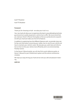 3
3 4
4 5
5 6
6 7
7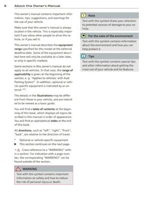 8
8 9
9 10
10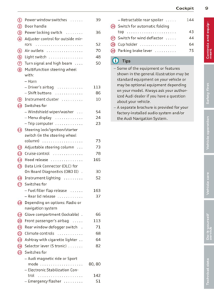 11
11 12
12 13
13 14
14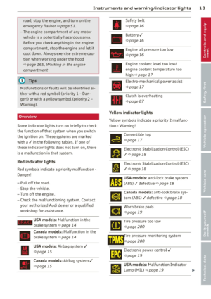 15
15 16
16 17
17 18
18 19
19 20
20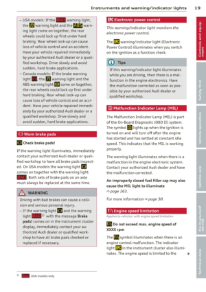 21
21 22
22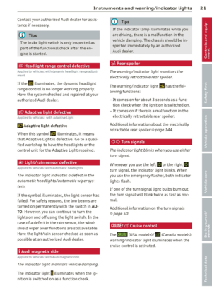 23
23 24
24 25
25 26
26 27
27 28
28 29
29 30
30 31
31 32
32 33
33 34
34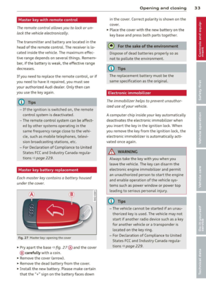 35
35 36
36 37
37 38
38 39
39 40
40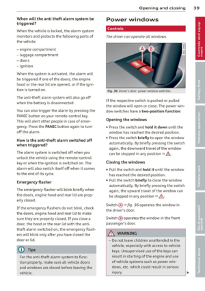 41
41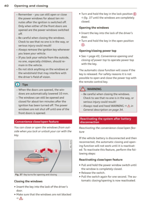 42
42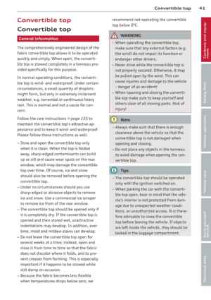 43
43 44
44 45
45 46
46 47
47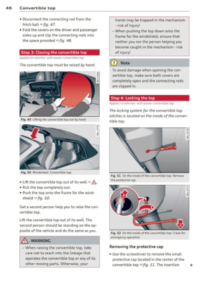 48
48 49
49 50
50 51
51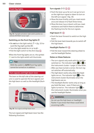 52
52 53
53 54
54 55
55 56
56 57
57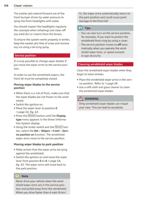 58
58 59
59 60
60 61
61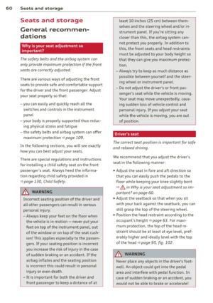 62
62 63
63 64
64 65
65 66
66 67
67 68
68 69
69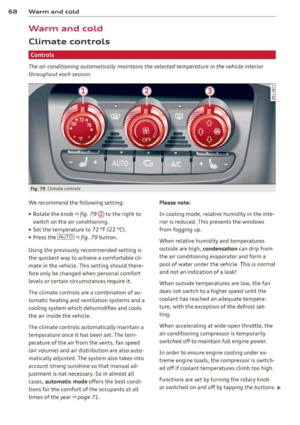 70
70 71
71 72
72 73
73 74
74 75
75 76
76 77
77 78
78 79
79 80
80 81
81 82
82 83
83 84
84 85
85 86
86 87
87 88
88 89
89 90
90 91
91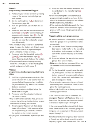 92
92 93
93 94
94 95
95 96
96 97
97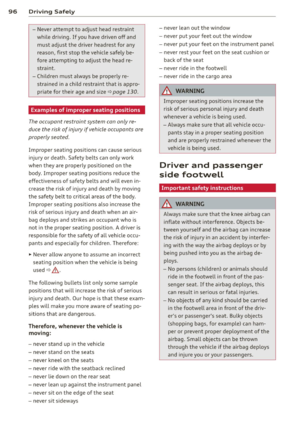 98
98 99
99 100
100 101
101 102
102 103
103 104
104 105
105 106
106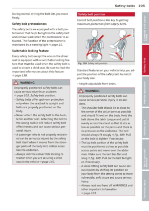 107
107 108
108 109
109 110
110 111
111 112
112 113
113 114
114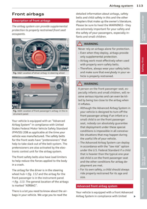 115
115 116
116 117
117 118
118 119
119 120
120 121
121 122
122 123
123 124
124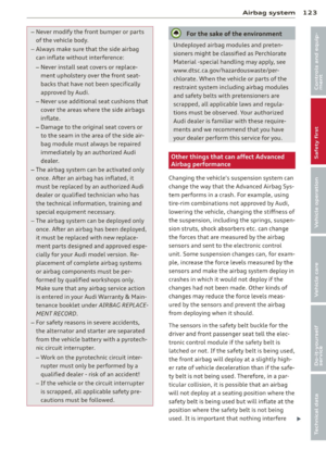 125
125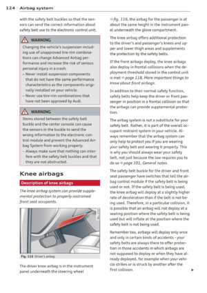 126
126 127
127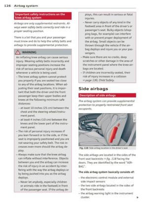 128
128 129
129 130
130 131
131 132
132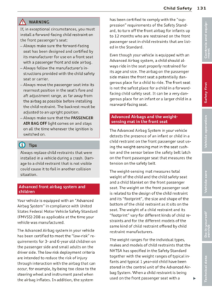 133
133 134
134 135
135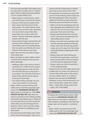 136
136 137
137 138
138 139
139 140
140 141
141 142
142 143
143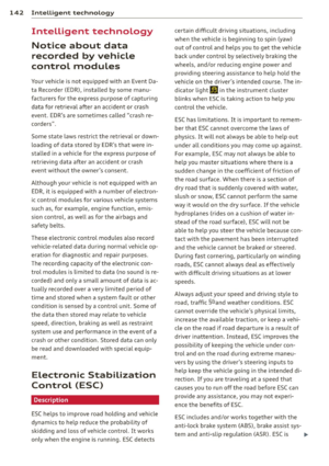 144
144 145
145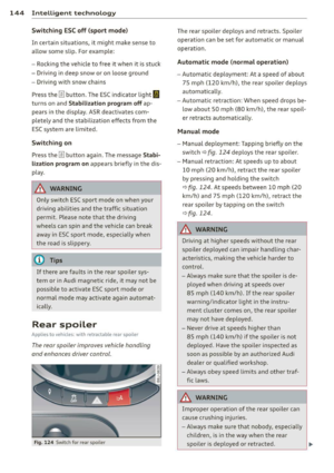 146
146 147
147 148
148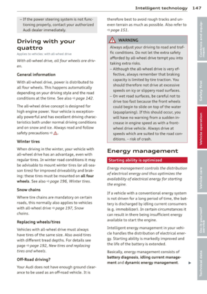 149
149 150
150 151
151 152
152 153
153 154
154 155
155 156
156 157
157 158
158 159
159 160
160 161
161 162
162 163
163 164
164 165
165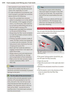 166
166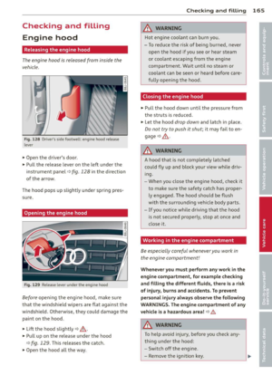 167
167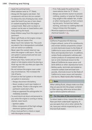 168
168 169
169 170
170 171
171 172
172 173
173 174
174 175
175 176
176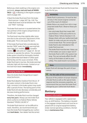 177
177 178
178 179
179 180
180 181
181 182
182 183
183 184
184 185
185 186
186 187
187 188
188 189
189 190
190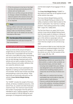 191
191 192
192 193
193 194
194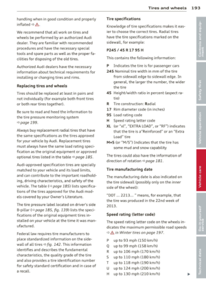 195
195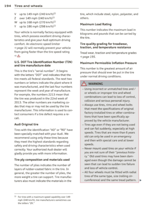 196
196 197
197 198
198 199
199 200
200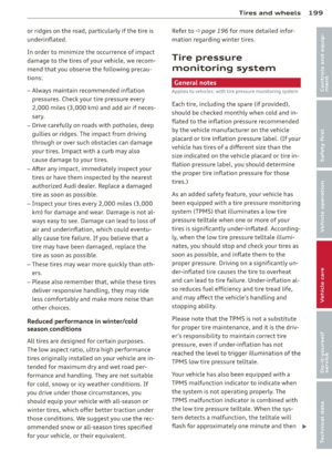 201
201 202
202 203
203 204
204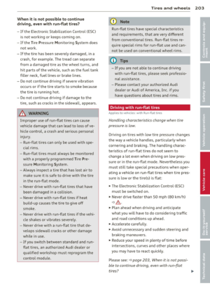 205
205 206
206 207
207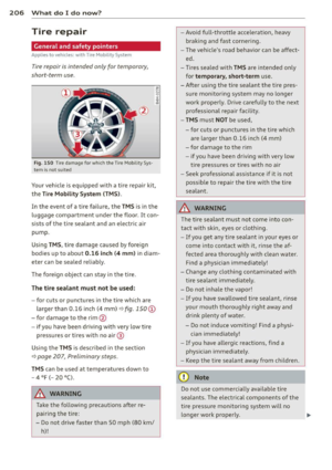 208
208 209
209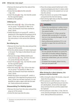 210
210 211
211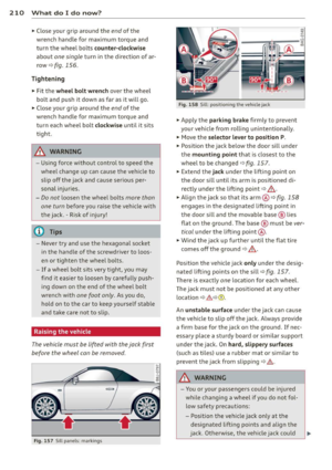 212
212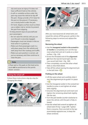 213
213 214
214 215
215 216
216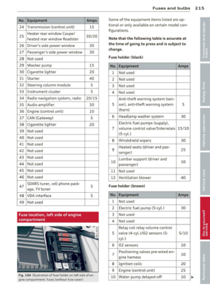 217
217 218
218 219
219 220
220 221
221 222
222 223
223 224
224 225
225 226
226 227
227 228
228 229
229 230
230 231
231 232
232 233
233 234
234 235
235 236
236 237
237 238
238 239
239 240
240 241
241 242
242 243
243