Page 161 of 274
 Owners Manual ■The cruise control system cannot be activated when the selector lever is in po-
sitions P , N or R (vehicles with automatic transmission).■
The cruise control system may automatically switch o")
■The cruise control system cannot be activated when the selector lever is in po-
sitions P , N or R (vehicles with automatic transmission).■
The cruise control system may automatically switch off when some brake assist
systems (e.g. ESC) intervene, when the maximum permissible engine speed is ex-
ceeded, etc.
Activating/deactivating
Fig. 135
Operating lever: Cruise control
system controls
First read and observe the introductory information and safety warn-
ings on page 157.
Activating
›
Move switch
A
» Fig. 135 into the ON position.
Deactivating
›
Move switch
A
» Fig. 135 into the OFF position.
Storing and maintaining speed
First read and observe the introductory information and safety warn-
ings
on page 157.
›
Activate the cruise control system » page 158.
›
Drive at the desired speed.
›
Push the rocker button
B
into the SET/- » Fig. 135 on page 158 position.
After you have released the rocker button
B
from the SET/- position, the speed
you have just stored is kept constant without having to depress the accelerator.
Changing the stored speed
First read and observe the introductory information and safety warn-
ings
on page 157.
Increasing the speed with the rocker button
B›
Push the rocker button
B
into the RES/+ » Fig. 135 on page 158 position.
If the rocker button is held in the RES/+ position, the speed will increase continu-
ously. Release the rocker button once the desired speed is reached. The set
speed is then stored in the memory.
Decreasing the speed using the rocker button
B
The stored speed can be reduced by pushing the rocker switch
B
into the
SET » Fig. 135 on page 158 position.
If the rocker button is pressed and held in the SET/- position, the speed will de-
crease continuously. Release the rocker button once the desired speed is
reached. The set speed is then stored in the memory.
If the rocker button is released at a speed of less than approx. 25 km/h, the speedis not stored and the memory is erased. Once the speed of the vehicle has in-
creased to more than approx. 25 km/h, the speed must then be stored again by
pushing the rocker button
B
into the SET/- position.
Increasing the speed with the accelerator
›
Depress the accelerator pedal.
Releasing the accelerator pedal will cause the speed to drop again to the set
speed.
Decreasing the speed with the brake pedal
The speed can also be reduced by depressing the brake pedal, which temporarily
deactivates the system » page 158.
Switching off temporarily
First read and observe the introductory information and safety warn-
ings
on page 157.
The cruise control system can be temporarily deactivated by pushing the switch
A
» Fig. 135 on page 158into the spring-mounted CANCEL position or by depress-
ing the brake or clutch pedal.
The set speed remains stored in the memory.
158Driving
Page 162 of 274
 Owners Manual Briefly push the rocker button B into the RES/+ position in order to resume the
stored speed after the clutch or brake pedal is released.
START-STOP
Introduction
This chapter contains informat")
Briefly push the rocker button B into the RES/+ position in order to resume the
stored speed after the clutch or brake pedal is released.
START-STOP
Introduction
This chapter contains information on the following subjects:
Starting/shutting down the engine
159
Operating conditions of the system
160
Manually activating/deactivating the system
160
Information messages
161
The START-STOP system helps you to save fuel while at the same time reducing
harmful exhaust emissions and CO 2 emissions.
The function is automatically activated each time the ignition is switched on. In the start-stop mode, the engine automatically switches to the vehicle's idle phase, e.g. when stopped at traffic lights. The engine restarts automatically
where necessary.
The system can work only if the following basic conditions are met. The driver's door is closed.
The driver has fastened the seat belt.
The bonnet is closed.The driving speed was higher than 4 km.h after the last stop.
No trailer is coupled.
WARNING■ The brake servo unit and power steering only operate if the engine is run-
ning.■
Never let the vehicle roll with the engine switched off.
CAUTION
Always deactivate the START-STOP system before driving through wa-
ter » page 148 .Note■
If the driver's seat belt is removed for more than approx. 30 seconds or the driv-
er's door is opened during stop mode on vehicles with manual transmission or au- tomatic transmission (when the selector lever in position P), the engine must be
started manually » page 133.■
After manually starting the engine on vehicles with manual transmission, auto-
matic engine shut down is not possible until the vehicle has travelled the re-
quired minimum distance for START-STOP mode.
■
If, on vehicles with automatic transmission, the selector lever positions D, S or N
are selected after driving in reverse, the vehicle will first need to achieve a speed
of over 10 km/h before automatic engine shut down can take place again.
■
Changes to the outdoor temperature can have an effect on the internal temper-
ature of the vehicle battery even after several hours. If the vehicle remains out-
doors for a long time in minus temperatures or in direct sunlight, it can take sev-
eral hours until the internal temperature of the vehicle battery reaches a suitable temperature for proper operation of the START STOP system.
■
If Climatronic is running in automatic mode, the engine may not switch off auto-
matically under certain conditions.
Starting/shutting down the engine
First read and observe the introductory information and safety warn-ings
on page 159.
Vehicles with manual transmission
›
Stop the vehicle (where necessary, apply the handbrake).
›
Put the gear stick into Neutral.
›
Release the clutch pedal.
Automatic engine shut down (STOP phase) takes place. The warning symbol
appears in the instrument cluster display.
›
Depress the clutch pedal.
The automatic start procedure takes place again (START phase). The warning
symbol
goes out.
Vehicles with automatic transmission
›
Bring the vehicle to a stop and depress the brake pedal.
Automatic engine shut down takes place. The warning symbol
appears in the
instrument cluster display.
›
Release the brake pedal.
159Assist systems
Page 163 of 274
 Owners Manual The automatic start procedure takes place again. The warning symbol goes
out.
Further information on automatic transmission Engine shut down takes place when the selector lever is in positions P,")
The automatic start procedure takes place again. The warning symbol goes
out.
Further information on automatic transmission Engine shut down takes place when the selector lever is in positions P, D , S and N
and in Tiptronic mode.
When the selector lever is in position P, the engine remains shut down even after
you release the brake pedal. Start the engine by pressing the gas pedal or by moving the selector lever into a different mode and releasing the brake pedal.
If the selector lever is moved into position R during the STOP phase , the engine
will re-start.
No automatic engine shutdown takes place when the vehicle is moving at low speed (e.g. during a traffic jam or when tuning) and remains stationary after
pressing the brake pedal lightly. Automatic engine shutdown takes place if you
press the brake pedal down with more force.
Operating conditions of the system
First read and observe the introductory information and safety warn-ings
on page 159.
The START-STOP system is very complex. Some of the procedures are hard to check without servicing.
No engine shut down is carried out
Before each STOP phase, the system checks whether certain conditions have
been met. No engine shut down takes place in the following situations.
› The engine has not reached the minimum temperature for the START STOP
mode.
› The temperature inside the vehicle has not reached the temperature set in the
air-conditioning system.
› The external temperature is very low/high.
› The intensive windscreen heater (Climatronic) or windscreen heater/ventilation
is switched on with the maximum air temperature setting (manual air condition-
ing system).
› The parking aid/Park Assist is switched on.
› The charge state of the vehicle battery is too low.
› The stationary vehicle is on a steep slope or a steep downhill section.
› The idling speed is too high.
› The steering angle is too large (manoeuvring).
› The selector lever position
R is selected (e.g. when parking).
The warning symbol appears in the instrument cluster display.
The automatic start procedure takes place again
During the STOP phase, the engine fires up without any active driver intervention, e.g. in the following situations.
› The vehicle begins to roll, e.g. on a slope.
› The difference between the temperature setting of the air-conditioning system
and the inside temperature is too large.
› The intensive windscreen heater (Climatronic) or windscreen heater/ventilation
is switched on with the maximum air temperature setting (manual air condition-
ing system).
› The brake pedal was pressed several times (the pressure in the braking system
is too low).
› The charge state of the vehicle battery is too low.
› The current consumption is too high.
Manually activating/deactivating the system
Fig. 136
Button for the START-STOP sys-
tem
First read and observe the introductory information and safety warn-
ings on page 159.
Activation/deactivation
›
Press the symbol button
» Fig. 136 .
When start-stop mode is deactivated, the indicator light in the button lights up.
Note
If the system is deactivated during the STOP phase, the automatic start proce-
dure takes place.
160Driving
Page 164 of 274
 Owners Manual Information messagesFirst read and observe the introductory information and safety warn-
ings
on page 159.
The messages and information are indicated in the instrument cluster display.
Start the eng")
Information messagesFirst read and observe the introductory information and safety warn-
ings
on page 159.
The messages and information are indicated in the instrument cluster display.
Start the engine manually!
START MANUALLY
The driver sees this message when the conditions for the automatic start proce-
dure are not met during the STOP phase. The engine must be started manual-
ly » page 135 .
Error: start-stop system
ERROR START-STOP
Error in the START-STOP system. Seek help from a specialist garage.
Fatigue detection (break recommendation)
Introduction
This chapter contains information on the following subjects:
Function
161
Information messages
161WARNING■ For the driving ability is always the driver's responsibility. Never drive if you
feel tired.■
The system may not detect all cases where a break is needed.
■
Therefore, take regular, sufficient breaks during long trips.
■
There will be no system warning during the so-called micro-sleep.
Note
■ In some situations, the system may evaluate the driving incorrectly and thus
mistakenly recommend a break (e.g. sporty driving, adverse weather conditions or poor road conditions).■
The fatigue detection system is designed primarily for motorway driving.
Function
First read and observe the introductory information and safety warn-ings
on page 161.
The fatigue detection system advises the driver on the basis of information about
the steering behaviour, to take a break from driving. The system recommends a
break at speeds of 65-200 km/h.
After the ignition has been switched on, the system evaluates the steering be-
haviour for 15 minutes. This baseline analysis is constantly compared with the
current steering behaviour.
If the system detects deviations from normal steering behaviour due to possible
fatigue of the driver, it recommends to take a break from driving.
The system deletes the stored baseline analysis if one of the following condi-
tions is met.
› The vehicle is stopped and the ignition switched off.
› The vehicle is stopped, the seat belt removed and the driver's door opened.
› The vehicle is stopped for more than 15 minutes.
If none of these conditions are met or if the driving style is not changed, the sys-
tem recommends a driving break again after 15 minutes.
Activation/deactivation
The system can be activated/deactivated via the MAXI DOT display in the Wizards
menu option » page 28.
Information messages
First read and observe the introductory information and safety warn-
ings
on page 161.
The symbol will appear in the MAXI DOT display for a few seconds, along with
the following message.
Fatigue detected. Take a break.
An audible signal is also emitted.
161Assist systems
Page 165 of 274
 Owners Manual Towing a trailer
Towing device
Introduction
This chapter contains information on the following subjects:
Description
162
Adjusting the ready position
163
Fitting the ball head
163
Check proper fitt")
Towing a trailer
Towing device
Introduction
This chapter contains information on the following subjects:
Description
162
Adjusting the ready position
163
Fitting the ball head
163
Check proper fitting
164
Removing the ball head
164
Use and care
165
If your vehicle has already been factory-fitted with a towing device or is fitted
with a towing device from ŠKODA Original Accessories, then it meets all of the
technical requirements and national legal regulations for towing a trailer.
Your vehicle is fitted with a 13-pin power socket for the electrical connection be-
tween the vehicle and trailer. If the trailer that is to be towed has a 7-pin connec-
tor , you can use a suitable adapter from ŠKODA Original Accessories.
The maximum trailer drawbar load is 80 kg.
WARNING■
Check that the tow bar is seated correctly and is secured in the mounting
recess before the start of every journey.■
Do not use the tow bar if it is not correctly inserted and secured in the
mounting recess.
■
Do not use the towing device if it is damaged or if there are parts missing.
■
Do not modify or adapt the towing device in any way.
■
Never release the tow bar while the trailer is still coupled.
CAUTION
Take care when handling the tow bar so as to avoid damaging the paintwork on
the bumper.
DescriptionFig. 137
Carrier for the towing device/tow bar
First read and observe the introductory information and safety warn-
ings
on page 162.
The tow bar can be removed and is kept in the spare wheel compartment or in a
compartment for the spare wheel in the boot » page 228, Vehicle tool kit .
Explanation of graphic 13-pin power socket
Safety eyelet
Mounting recess
Cap
Dust cap
Tow ball
Operating lever
Lock cap
Release pin
Key
Locking ball
Note
If you lose the key, please get in touch with a specialist garage.
1234567891011162Driving
Page 166 of 274
 Owners Manual Adjusting the ready positionFig. 138
Setting the ready position/ready position
First read and observe the introductory information and safety warn- ings
on page 162.
Always adjust the ball head in")
Adjusting the ready positionFig. 138
Setting the ready position/ready position
First read and observe the introductory information and safety warn- ings
on page 162.
Always adjust the ball head in the ready position before fitting.
›
Turn the key
1
so that its red marking is visible » Fig. 138.
›
Grip the tow bar below the protective cap
2
.
›
Press the release pin
3
in the direction of the arrow to the stop, and simulta-
neously push the lever
4
downwards in the direction of the arrow to the stop.
The lever remains locked in this position.
CAUTION
In the ready position, the key cannot be removed nor turned to a different posi-
tion.
Fitting the ball headFig. 139
Insert the ball head/lock the lock, and put the lock cover on
First read and observe the introductory information and safety warn-
ings
on page 162.
›
Pull cap
4
» Fig. 137 on page 162 downwards.
›
Put the tow bar in the ready position » page 163.
›
Grip the tow bar from underneath » Fig. 139 and insert into the mounting recess
until you hear it click into place » .
The lever
1
automatically turns upwards and the release pin
2
pops out (its red
and green parts are visible) » .
If the lever
1
does not turn automatically, or if the release pin
2
does not pop
out, remove the tow bar from the mounting recess by turning the lever down-
wards as far as it can go. Clean the tapered surfaces on the tow bar and the
mounting recess.
›
Lock the lock on the operating lever by turning the key
3
by 180° to the right
(see green marking 3 is visible) and remove the key in the direction of the arrow.
›
Insert the cap
4
onto the lock in the direction of the arrow » .
›
Check that the tow bar is securely attached » page 164.
WARNING■
Keep your hands outside the lever's range of motion when attaching the
tow bar – risk of finger injuries!■
Never attempt to pull the operating lever upwards forcibly to turn the key.
Doing so would mean the ball head is not attached correctly. 163Towing a trailer
Page 167 of 274
 Owners Manual CAUTION■After removing the key, always replace the cap on the lock of the operating lev-
er – risk of dirt getting into the lock.■
Keep the mounting recess of the towing equipment clean at all")
CAUTION■After removing the key, always replace the cap on the lock of the operating lev-
er – risk of dirt getting into the lock.■
Keep the mounting recess of the towing equipment clean at all times. Such dirt
prevents the ball head from being attached securely.
■
After removing the ball head, always place the cap on the mounting recess.
Check proper fitting
Fig. 140
Check that the tow bar is attach-
ed properly
First read and observe the introductory information and safety warn-
ings on page 162.
Check that the tow bar is fitted properly before each use.
Check the following points.
The lever
1
is right at the top » Fig. 140.
The release pin
2
is completely exposed (both its red and green parts are
visible).
The key is removed.
The cap
3
is on the lock of the operating lever.
The tow bar does not come out of the mounting recess even after heavy
“shaking”.
WARNINGDo not use the towing device unless the tow bar has been properly locked!
Removing the ball headFig. 141
Unlock the operating lever of the ball head/removing the ball head
First read and observe the introductory information and safety warn-
ings
on page 162.
›
Remove the cap
1
» Fig. 141 from the lock on the tow bar in the direction of the
arrow.
›
Unlock the lock on the operating lever by turning the key
2
180° to the left so
that the red marking becomes visible.
›
Grasp the ball head from underneath.
›
Press the release pin
3
in the direction of the arrow to the stop, and simulta-
neously push the lever
4
downwards in the direction of the arrow to the stop.
The ball head is released in this position and falls freely into the hand. If it does
not fall freely into the hand, use your other hand to push it upwards.
At the same time, the tow bar latches into the ready position and is thereforeready to be re-inserted into the mounting recess »
.
›
Place the cap
4
» Fig. 137 on page 162 onto the mounting recess.
WARNINGNever allow the tow bar to remain unsecured in the boot. This could cause
boot damage on sudden braking, and could put the safety of the occupants at
risk. 164Driving
Page 168 of 274
 Owners Manual CAUTION■If the lever is held firm and not pushed downwards as far as it can go, it will go
back up after the ball head is removed and will not latch into the ready position.
The tow bar will then ne")
CAUTION■If the lever is held firm and not pushed downwards as far as it can go, it will go
back up after the ball head is removed and will not latch into the ready position.
The tow bar will then need to be brought into this position before the next time it is fitted.■
Stow the ball head in the ready position with the key inserted in the box. When
doing so, make the side opposite to the inserted key face downwards – there is a
risk of damaging the key.
■
Do not use excessive force when handling the operating lever (e.g. do not step
on it).
Note
■ We recommend putting the protective cover onto the ball head before removing
the tow bar.■
Clean any dirt from the tow bar before stowing it away in the box with the vehi-
cle tool kit.
Use and care
First read and observe the introductory information and safety warn-
ings
on page 162.
Close the mounting recess with the cover to prevent any dirt from getting in.
Always check the tow bar before hitching a trailer. Apply suitable grease where
necessary.
Use the protective cover when stowing away the tow bar, in order to stop the
boot from getting dirty.
In the event of dirt, clean the surfaces of the mounting recess and treat with a
suitable preservative.
CAUTION
Apply grease to the upper part of the mounting recess. Make sure you do not re-
move any grease.
Trailer
Introduction
This chapter contains information on the following subjects:
Loading a trailer
165
Driving with a trailer
166
Trailer stabilisation
167
Anti-theft alarm system
167WARNINGAlways drive particularly carefully with the trailer.
Loading a trailer
First read and observe the introductory information and safety warn-
ings
on page 165.
The vehicle/trailer combination must be balanced, whereby the maximum permis-
sible drawbar load must be utilised. If the drawbar load is too low, it jeopardises the performance of the vehicle/trailer combination.
Distribution of the load
Distribute the load in the trailer in such a way that heavy items are located as close to the axle as possible. Secure the items from slipping.
The distribution of the weight is very poor if your vehicle is unladen and the trail-
er is laden. Maintain a particularly low speed if you cannot avoid driving with this combination.
Tyre pressure
Correct the tyre inflation pressure on your vehicle for a “full load” » page 221,
Service life of tyres .
Trailer load
The permissible trailer load must not be exceeded under any circumstan-
ces » page 252 , Technical data .
The trailer loads specified apply only to altitudes up to 1 000 metres above mean
sea level.
165Towing a trailer
 1
1 2
2 3
3 4
4 5
5 6
6 7
7 8
8 9
9 10
10 11
11 12
12 13
13 14
14 15
15 16
16 17
17 18
18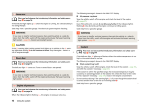 19
19 20
20 21
21 22
22 23
23 24
24 25
25 26
26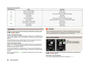 27
27 28
28 29
29 30
30 31
31 32
32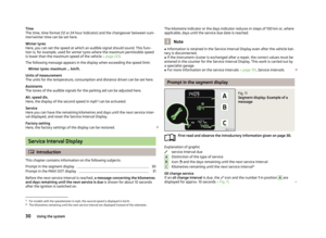 33
33 34
34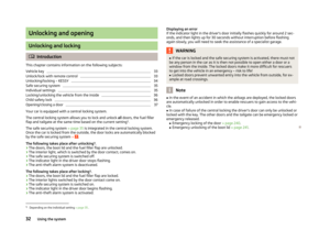 35
35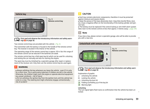 36
36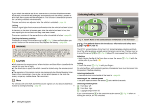 37
37 38
38 39
39 40
40 41
41 42
42 43
43 44
44 45
45 46
46 47
47 48
48 49
49 50
50 51
51 52
52 53
53 54
54 55
55 56
56 57
57 58
58 59
59 60
60 61
61 62
62 63
63 64
64 65
65 66
66 67
67 68
68 69
69 70
70 71
71 72
72 73
73 74
74 75
75 76
76 77
77 78
78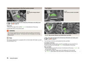 79
79 80
80 81
81 82
82 83
83 84
84 85
85 86
86 87
87 88
88 89
89 90
90 91
91 92
92 93
93 94
94 95
95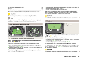 96
96 97
97 98
98 99
99 100
100 101
101 102
102 103
103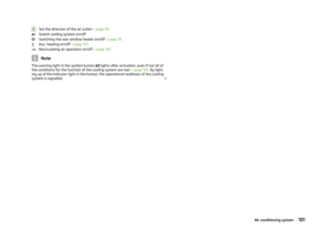 104
104 105
105 106
106 107
107 108
108 109
109 110
110 111
111 112
112 113
113 114
114 115
115 116
116 117
117 118
118 119
119 120
120 121
121 122
122 123
123 124
124 125
125 126
126 127
127 128
128 129
129 130
130 131
131 132
132 133
133 134
134 135
135 136
136 137
137 138
138 139
139 140
140 141
141 142
142 143
143 144
144 145
145 146
146 147
147 148
148 149
149 150
150 151
151 152
152 153
153 154
154 155
155 156
156 157
157 158
158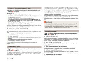 159
159 160
160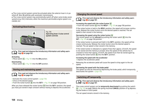 161
161 162
162 163
163 164
164 165
165 166
166 167
167 168
168 169
169 170
170 171
171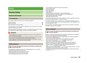 172
172 173
173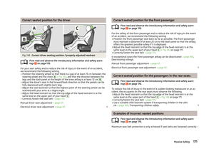 174
174 175
175 176
176 177
177 178
178 179
179 180
180 181
181 182
182 183
183 184
184 185
185 186
186 187
187 188
188 189
189 190
190 191
191 192
192 193
193 194
194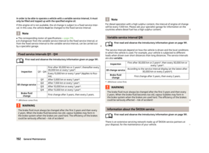 195
195 196
196 197
197 198
198 199
199 200
200 201
201 202
202 203
203 204
204 205
205 206
206 207
207 208
208 209
209 210
210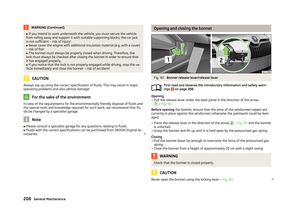 211
211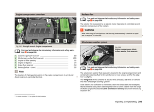 212
212 213
213 214
214 215
215 216
216 217
217 218
218 219
219 220
220 221
221 222
222 223
223 224
224 225
225 226
226 227
227 228
228 229
229 230
230 231
231 232
232 233
233 234
234 235
235 236
236 237
237 238
238 239
239 240
240 241
241 242
242 243
243 244
244 245
245 246
246 247
247 248
248 249
249 250
250 251
251 252
252 253
253 254
254 255
255 256
256 257
257 258
258 259
259 260
260 261
261 262
262 263
263 264
264 265
265 266
266 267
267 268
268 269
269 270
270 271
271 272
272 273
273