Page 49 of 274
 Owners Manual The window can be completely opened automatically by briefly pressing the but-ton as far as the stop. Renewed pressing of the button causes the window tostop immediately.
Closing›
Pull gently on the")
The window can be completely opened automatically by briefly pressing the but-ton as far as the stop. Renewed pressing of the button causes the window tostop immediately.
Closing›
Pull gently on the top edge of the corresponding button and hold until the win-
dow has moved into the desired position. Releasing the button causes the win-
dow to stop immediately.
The window can also be fully closed automatically by pulling the button up to the
stop. Renewed pulling of the button causes the window to stop immediately.
Force limit
First read and observe the introductory information and safety warn-ings
on page 44.
The electrical power window system is fitted with a force limiter. It reduces the
risk of bruises or injuries when closing the windows.
If there is an obstacle, the closing process is stopped and the window goes down
by several centimetres.
If the obstacle prevents the window from being closed during the next 10 sec-
onds, the closing process is interrupted once again and the window goes down by several centimetres.
If you attempt to close the window again within 10 seconds of the window being moved down for the second time, even though the obstacle was not yet been re-moved, the closing process is only stopped. During this time it is not possible to
automatically close the window. The force limiter is still switched on.
The force limiter is only switched off if you attempt to close the window again
within the next 10 seconds - the window will now close with full force!
If you wait longer than 10 seconds, the force limiter is switched on again.
Window convenience operation
First read and observe the introductory information and safety warn-ings
on page 44.
The windows can be operated by the locking or unlocking.
The prerequisite for ensuring that the convenience operating feature correctly is the automatic opening/closing of all windows is operational.
Opening can take place in one of the following ways.
›
Press and hold the symbol button on the key.
›
Hold the key in the driver's lock in the unlock position.
›
Press and hold the upper part of the central locking button in the driver's
door » page 36 .
›
Hold the button
A
1)
in the opening position » Fig. 25 on page 45.
Closing can take place in one of the following ways.
›
Press and hold the symbol button
on the key.
›
Hold the key in the driver's lock in the lock position.
›
Press and hold the lower part of the central locking button » page 36 in the
driver's door.
›
Hold the button
A
1) in the closing position » Fig. 25 on page 45.
›
In the KESSY system, hold a finger on the sensor
1
» Fig. 14 on page 34.
You can interrupt the opening or closing process for the windows immediately by
releasing the key or the the button
A
and interrupting the locking/unlocking.
Convenience opening or closing the window using the key in the driver's lock is
only possible within 45 seconds after locking the vehicle.
Operational faults
First read and observe the introductory information and safety warn-
ings
on page 44.
The automatic power windows do not work if the vehicle battery was disconnec- ted and connected while a window is open. The system must be activated.
Activation sequence:
1)
Convenience opening and closing the windows with the button
A
is possible immediately after un-
locking the vehicle or turning off the ignition and opening the driver's or front passenger's door.
46Using the system
Page 50 of 274
 Owners Manual ›Switch on the ignition.›Pull the top edge of the button and close the window.›
Release the button.
›
Pull the relevant button upwards again for approx. 3 seconds, and keep it press-
ed down.")
›Switch on the ignition.›Pull the top edge of the button and close the window.›
Release the button.
›
Pull the relevant button upwards again for approx. 3 seconds, and keep it press-
ed down.
Electric sliding/tilting roof
Introduction
This chapter contains information on the following subjects:
Operation
47
Convenience operation of sliding/tilting roof
48
Electric sliding/tilting roof with solar cells
48
The electric sliding/tilting roof (abbreviated in the following as 'sliding/tilting
roof') can only be operated when the ignition is turned on and when the outdoor
temperature is higher than -20 °C.
The sliding/tilting roof can still be operated for approx. 10 minutes after switchingthe ignition off. However, as soon as the driver or front passenger's door is
opened it is no longer possible to operate the sliding/tilting roof.
CAUTION
■ Always close the sliding/tilting roof before disconnecting the battery.■If the battery has been disconnected and reconnected, it is possible that the
sliding/tilting roof does not operate correctly. In this case, turn the rotary switch
to the switch position A
» Fig. 27 on page 47 and push forward for about 10 sec-
onds.
OperationFig. 27
Control dial for the sliding/tilting
roof
First read and observe the introductory information and safety warn-
ings on page 47.
Comfort position
›
Turn the switch to position
C
» Fig. 27 .
When the sliding/tilting roof is in the comfort position, the intensity of the wind
noise is reduced.
Open partially
›
Simply turn the knob to a point between
A
and
C.
Open fully
›
Turn the switch to position
B
and hold it in this position (spring-tensioned po-
sition).
Tilting roof
›
Turn the switch to position
D
.
Closing
›
Turn the switch to position
A
.
Force limiter
The sliding/tilting roof is fitted with a force limiter. If an obstacle (e.g. ice) pre-
vents closing, the sliding/tilting roof stops and opens completely. The sliding/tilt- ing roof can be closed completely without the force limiter by turning the switchinto position
A
» Fig. 27 at the front for as long as it takes for the sliding/tilting
roof to close completely » .
47Unlocking and opening
Page 51 of 274
 Owners Manual WARNINGWhen closing the sliding/tilting roof proceed with caution to avoid causing
crushing injuries – risk of injury!
CAUTION
During the winter it may be necessary to remove any ice and snow in the")
WARNINGWhen closing the sliding/tilting roof proceed with caution to avoid causing
crushing injuries – risk of injury!
CAUTION
During the winter it may be necessary to remove any ice and snow in the vicinity
of the sliding/tilting roof before opening it to prevent any damage to the opening
mechanism.
Convenience operation of sliding/tilting roof
First read and observe the introductory information and safety warn-ings
on page 47.
The sliding/tilting roof can be operated by locking/unlocking using the key or us-
ing the KESSY system with the aid of the sensor
1
» Fig. 14 on page 34.
›
Press and hold the symbol button
on the key.
›
In the KESSY system, hold a finger on the sensor
1
» Fig. 14 on page 34.
By releasing the lock or lifting your finger off the sensor
1
when using the KESSY
system, the closing process is immediately interrupted.
WARNINGClose the sliding/tilting roof carefully – risk of injury! The force limiter does not
work when convenience closing is in operation.
Electric sliding/tilting roof with solar cells
First read and observe the introductory information and safety warn-ings
on page 47.
If there is sufficient bright sunlight, the solar cells in the sliding/tilting roof deliver
the electrical power for the fresh air blower. Further information » page 103, Cli-
matronic (automatic air conditioning system) .
The operation of the sliding/tilting roof with solar cells is the same as of a normal
sliding/tilting roof.
Panoramic sliding roof (Superb Combi)
Introduction
This chapter contains information on the following subjects:
Operation
49
Opening/closing the sun screen
49
Convenience operation of Sliding/tilting roof
50
The panoramic sliding/tilting roof (abbreviated in the following as 'sliding/tilting
roof') can only be operated when the ignition is turned on and when the outdoor temperature is higher than -20 °C.
The sliding/tilting roof can still be operated for approx. 10 minutes after switchingthe ignition off. However, as soon as the driver or front passenger's door is
opened it is no longer possible to operate the sliding/tilting roof.
CAUTION
■ Always close the sliding/tilting roof before disconnecting the battery.■If, for example, the battery has been disconnected and reconnected, it is possi-
ble that the sliding/tilting roof does not operate correctly. Next, move the rotary
switch into position A
» Fig. 28 on page 49, pull the recess firmly downwards
and forwards. The sliding/tilting roof opens and closes again after around 10 sec-
onds. Do not release the control dial until it has done so.
■
If, for example, the battery has been disconnected and reconnected, it is possi-
ble that the sun screen does not operate correctly. Then turn the switch to posi-
tion
A
» Fig. 28 on page 49and press and hold the button
G
» Fig. 29 on
page 49. The sun screen opens and closes again after around 10 seconds. Do
not release the control dial until it has done so.
48Using the system
Page 52 of 274
 Owners Manual OperationFig. 28
Control dial for the sliding/tilting
roof
First read and observe the introductory information and safety warn-
ings on page 48.
Comfort position
›
Turn the switch to position
C")
OperationFig. 28
Control dial for the sliding/tilting
roof
First read and observe the introductory information and safety warn-
ings on page 48.
Comfort position
›
Turn the switch to position
C
» Fig. 28 .
When the sliding/tilting roof is in the comfort position, the intensity of the wind
noise is reduced.
Open partially
›
Turn the switch to a position in area
D
.
Open fully
›
Turn the switch to position
B
and hold it in this position (spring-tensioned po-
sition).
Tilting roof
›
Turn the switch to position
A
.
›
Press the switch in the region
E
towards the roof.
Closing
›
Turn the switch to position
A
.
›
Press the switch on the recess
E
down and pull forwards.
Force limiter
The sliding/tilting roof is fitted with a force limiter. The sliding/tilting roof stops and moves back several centimetres when it cannot be closed because there is
something in the way (e.g. ice). The sliding/tilting roof can be fully closed without
a force limiter by pressing the switch on the recess
E
down and then pushing it
forward until the sliding/tilting roof is fully closed » .
WARNINGWhen closing the sliding/tilting roof proceed with caution to avoid causing
crushing injuries – risk of injury!
CAUTION
During the winter it may be necessary to remove any ice and snow in the vicinity
of the sliding/tilting roof before opening it to prevent any damage to the opening
mechanism.
Opening/closing the sun screen
Fig. 29
Buttons for sun screen
First read and observe the introductory information and safety warn- ings on page 48.
The sun screen can be closed or opened using the buttons » Fig. 29.
Opening
›
Briefly press the button
F
» Fig. 29 to open fully.
›
Press and hold the button
F
to open to the desired position.
The opening process stops when one releases the button.
Closing
›
Briefly press the button
G
» Fig. 29 to close fully.
›
Press and hold the button
G
to close in the desired position.
The closing process stops when one releases the button.
49Unlocking and opening
Page 53 of 274
Convenience operation of Sliding/tilting roofFirst read and observe the introductory information and safety warn-ings
on page 48.
The sliding/tilting roof can be operated by locking/unlocking using the key or us-
ing the KESSY system with the aid of the sensor
1
» Fig. 14 on page 34.
Closing
›
Hold down the symbol button on the key, or when using the KESSY system,
keep your finger on the sensor
1
» Fig. 14 on page 34 » .
By releasing the lock or lifting your finger off the sensor
1
when using the KESSY
system, the closing process is immediately interrupted.
Tilting roof
›
Press and hold the symbol button
on the key.
WARNINGClose the sliding/tilting roof carefully – risk of injury! The force limiter does not
work when convenience closing is in operation.
50Using the system
Page 54 of 274
 Owners Manual Lights and visibility
Lights
Introduction
This chapter contains information on the following subjects:
Parking and low beam lights
51
Daylight running lights (DAY LIGHT)
52
Turn signal and main bea")
Lights and visibility
Lights
Introduction
This chapter contains information on the following subjects:
Parking and low beam lights
51
Daylight running lights (DAY LIGHT)
52
Turn signal and main beam
53
Automatic driving lamp control
53
Adaptive headlights (AFS)
54
Fog lights
55
Fog lights with the CORNERfunction
55
Rear fog light
55
COMING HOME / LEAVING HOME
55
Hazard warning light system
56
Parking lights
57
Unless otherwise stated, the lights only work when the ignition is switched on.
On models fitted with right-hand steering the position of the controls differs
from that shown in » Fig. 30 on page 51. The symbols which mark the positions
of the controls are identical.
Keep the headlights lenses clean. The following guidelines must be ob-
served » page 200 , Headlight lenses .
WARNING■
The activation of the lights should only be undertaken in accordance with
national legal requirements.■
The driver is always responsible for the correct settings and use of the
lights.
WARNING (Continued)■ The automatic driving lamp control only operates as a support and does
not release the driver from his responsibility to check the light and, if necessa-
ry, to switch on the light depending on the given light conditions. The light
sensor cannot, for example, detect rain or snow. Under these conditions we
recommend switching on the low beam or fog lights!■
Never drive with only the side lights on! The side lights are not bright
enough to light up the road sufficiently in front of you or to be seen by other
oncoming traffic. Therefore always switch on the low beam when it is dark or
if visibility is poor.
Note
The headlights may mist up temporarily. When the driving lights are switched on,
the light outlet surfaces are free from mist after a short period, although the
headlight lenses may still be misted up in the peripheral areas. This mist has no
influence on the life of the lighting system.
Parking and low beam lights
Fig. 30
Light switches, knobs for head-
light beam adjustment and
brightness of instrument illumi-
nation
First read and observe the introductory information and safety warn- ings on page 51.
A
light switch positions » Fig. 30
Switching on the parking light or parking lights on both sides » page 57
Turn on the low beam
Switching off lights (except daytime running lights) Switching on the front fog lamp » page 55
Switching on the rear fog light » page 55
51Lights and visibility
Page 55 of 274
 Owners Manual Lights and visibility
Turning the rotary switch from position to gradually activates the headlight
beam adjustment, thereby shortening the beam of light » Fig. 30, position B
.
The")
Lights and visibility
Turning the rotary switch from position to gradually activates the headlight
beam adjustment, thereby shortening the beam of light » Fig. 30, position B
.
The positions of the width of illumination correspond approximately to the fol-
lowing car load.
Front seats occupied, boot empty
All seats occupied, boot empty
All seats occupied, boot loaded
Driver seat occupied, boot loaded
Instrument lighting
Turning the rotary switch
when the lights are switched on adjusts the bright-
ness of the instrument lighting » Fig. 30, position
C
.
The instruments are also illuminated when the side light, low or high beam light is switched on.
WARNINGAlways adjust the headlight beam to satisfy the following conditions.■The vehicle does not dazzle other road users, especially oncoming vehicles.■
The beam range is sufficient for safe driving.
Note
■ We recommend you adjust the headlight beam when the low beam is switched
on.■
The Bi-Xenon bulbs adapt automatically to the load and driving state of the ve-
hicle when the ignition is switched on and when driving. Vehicles that are equip- ped with Bi-Xenon headlights do not have a manual headlight range adjustment
control.
■
The low beam continues to shine while the ignition is switched on and the light
switch is in the position or . After switching off the ignition, the low beam
is switched off automatically and only the side lights come on. The side light goes
out after the ignition key is removed.
■
If there is a fault in the light switch, the low beam comes on automatically.
Daylight running lights (DAY LIGHT)
First read and observe the introductory information and safety warn-
ings
on page 51.
The daytime running lights function provides the lighting of the front of the vehi-
cle.
Switching on daytime running lights
›
The light switch is in position
A
or turn » Fig. 30 on page 51.
Deactivating the function daylight driving lights
›
Pull the turn signal and main beam lever to the steering wheel and push down-
wards » Fig. 31 on page 53.
›
At the same time switch on the ignition and hold the lever down in this position
for at least 3 seconds.
Activating the function daylight driving lights
›
Pull the turn signal and main beam lever to the steering wheel and push up- wards » Fig. 31 on page 53.
›
At the same time switch on the ignition and hold the lever down in this position
for at least 3 seconds.
The daytime running lights can be activated or deactivated via the Maxi DOT dis-
play in the menu item DRL » page 29 .
The daytime running lights are switched on automatically if the following condi- tions are met:
The ignition is switched on.
The daylight driving lights function is activated.
The light switch is in the position
or
» Fig. 30 on page 51.
Note
When the daytime running light is switched on, the side lights (neither at the
front or rear) and the number plate lights are not lit.
52Using the system
Page 56 of 274
 Owners Manual Turn signal and main beamFig. 31
Operating lever: Turn signal and
main beam operation
First read and observe the introductory information and safety warn-
ings on page 51.
Lever positions » Fig. 3")
Turn signal and main beamFig. 31
Operating lever: Turn signal and
main beam operation
First read and observe the introductory information and safety warn-
ings on page 51.
Lever positions » Fig. 31
Switch on right
turn signal
Switch on left
turn signal
Switch on high beam (spring-tensioned position)
Switch off main beam and headlamp flasher (spring-loaded position)
The parking light can also be controlled with the control lever » page 57.
The main beam can only be switched on when the low beam lights are on.
When the high beam or headlight flasher is on, the warning light
lights up in
the instrument cluster.
When the left or right turn signal is on, the warning light
or
flashes in the
instrument cluster.
Turn signal for changing lanes - to only flash briefly, only move the lever up or
down to the pressure point and hold it in this position.
Convenience turn signal
If you only wish to flash three times, briefly push the lever to the upper or lower
pressure point and release again.
The “Intelligent turn signal” can be activated or deactivated via the Maxi DOT dis-
play in the Intelligent turn signal » page 29 menu item.
ABCDWARNINGOnly turn on the main beam or the headlight flasher if other road users will
not be dazzled.
Note
■ The headlight flasher can be operated even if the ignition is switched off.■The turn signal light switches itself off automatically when driving around a
curve or after making a turn.■
The indicator light flashes at twice its normal rate if a bulb for the turn signal
light fails.
Automatic driving lamp control
Fig. 32
Light switch
First read and observe the introductory information and safety warn-
ings on page 51.
If the light switch is in position
» Fig. 32 , the parking lights, low beam and
number plate lights are switched on/off automatically.
The light is regulated based on data gathered by the light sensor attached be-
tween the windscreen and the interior mirror.
If the light switch is in position
, the symbol
lights up next to the light
switch. If the light is switched on automatically, the symbol
next to the light
switch also lights up.
Automatic headlight control in rain
If the light switch is in position
and if automatic wiping in rain or wiping (posi-
tion 2 or 3) is switched on for longer than 15 seconds » page 62, the parking
lights and low beam will switch on automatically.
53Lights and visibility
 1
1 2
2 3
3 4
4 5
5 6
6 7
7 8
8 9
9 10
10 11
11 12
12 13
13 14
14 15
15 16
16 17
17 18
18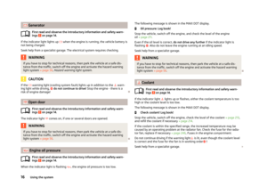 19
19 20
20 21
21 22
22 23
23 24
24 25
25 26
26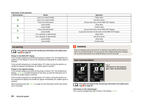 27
27 28
28 29
29 30
30 31
31 32
32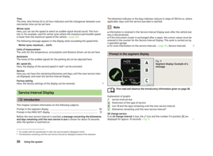 33
33 34
34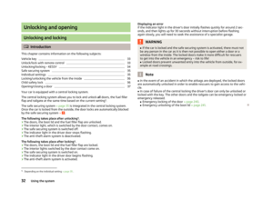 35
35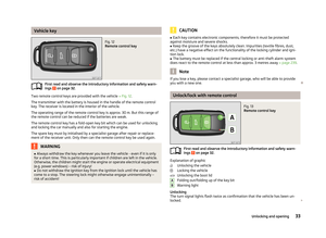 36
36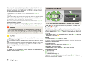 37
37 38
38 39
39 40
40 41
41 42
42 43
43 44
44 45
45 46
46 47
47 48
48 49
49 50
50 51
51 52
52 53
53 54
54 55
55 56
56 57
57 58
58 59
59 60
60 61
61 62
62 63
63 64
64 65
65 66
66 67
67 68
68 69
69 70
70 71
71 72
72 73
73 74
74 75
75 76
76 77
77 78
78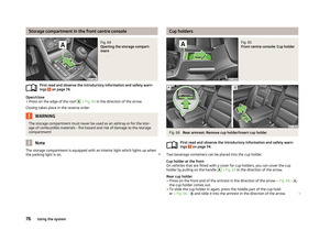 79
79 80
80 81
81 82
82 83
83 84
84 85
85 86
86 87
87 88
88 89
89 90
90 91
91 92
92 93
93 94
94 95
95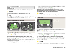 96
96 97
97 98
98 99
99 100
100 101
101 102
102 103
103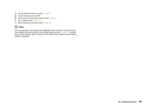 104
104 105
105 106
106 107
107 108
108 109
109 110
110 111
111 112
112 113
113 114
114 115
115 116
116 117
117 118
118 119
119 120
120 121
121 122
122 123
123 124
124 125
125 126
126 127
127 128
128 129
129 130
130 131
131 132
132 133
133 134
134 135
135 136
136 137
137 138
138 139
139 140
140 141
141 142
142 143
143 144
144 145
145 146
146 147
147 148
148 149
149 150
150 151
151 152
152 153
153 154
154 155
155 156
156 157
157 158
158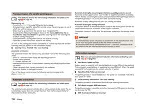 159
159 160
160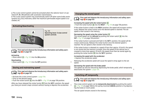 161
161 162
162 163
163 164
164 165
165 166
166 167
167 168
168 169
169 170
170 171
171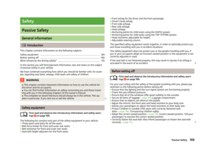 172
172 173
173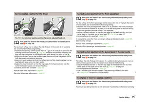 174
174 175
175 176
176 177
177 178
178 179
179 180
180 181
181 182
182 183
183 184
184 185
185 186
186 187
187 188
188 189
189 190
190 191
191 192
192 193
193 194
194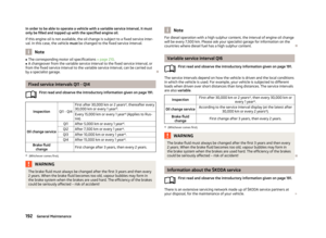 195
195 196
196 197
197 198
198 199
199 200
200 201
201 202
202 203
203 204
204 205
205 206
206 207
207 208
208 209
209 210
210 211
211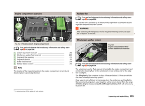 212
212 213
213 214
214 215
215 216
216 217
217 218
218 219
219 220
220 221
221 222
222 223
223 224
224 225
225 226
226 227
227 228
228 229
229 230
230 231
231 232
232 233
233 234
234 235
235 236
236 237
237 238
238 239
239 240
240 241
241 242
242 243
243 244
244 245
245 246
246 247
247 248
248 249
249 250
250 251
251 252
252 253
253 254
254 255
255 256
256 257
257 258
258 259
259 260
260 261
261 262
262 263
263 264
264 265
265 266
266 267
267 268
268 269
269 270
270 271
271 272
272 273
273 Owners Manual Convenience operation of Sliding/tilting roofFirst read and observe the introductory information and safety warn-ings
on page 48.
The sliding/tilting roof can be operated by locking/unlocking using")