Page 9 of 176

Mobility warranty and ŠKODA extendedwarranty.
Mobility warranty
Mobility warranty provides a sense of security when travelling in your vehicle.
Should your car break down when you're on the move one day as a result of an
unexpected fault, you will be eligible for services to ensure your continued mobili-
ty as part of the mobility warranty, which includes the following: Breakdown serv- ice at the breakdown location and towing off to the ŠKODA service partner, tech-
nical assistance by phone or on-site operation.
If your vehicle is not repaired on the same day, the ŠKODA service partner may
provide further services as required, such as replacement transportation (bus,
train, etc.), a courtesy vehicle, etc.
You can obtain more information regarding terms and conditions for the provision
of mobility warranty for your vehicle from your ŠKODA partner. Here you will also
be given detailed terms and conditions for the mobility warranty with respect to
your vehicle. In the event that there is no mobility warranty coverage available for
your vehicle, you should check with any ŠKODA service partner about the possibil-
ity of a subsequent agreement.
Note
The mobility guarantee is only available for some countries.
Optional ŠKODA extended warranty
If you received an extended ŠKODA warranty when purchasing your new car, the
two-year ŠKODA warranty for damages to your ŠKODA vehicle will be extended
by the time you chose or until the chosen mileage limit has been reached, which-
ever occurs first.
The previously mentioned paint warranty and the warranty against rust perfora-
tion stay unaffected by the extended warranty.
Detailed conditions for the extended warranty are included in the extended war- ranty terms and conditions, which your ŠKODA partner will have given to you
upon purchasing your new vehicle.
NoteThe mobility guarantee and optional ŠKODA extended warranty are only available
for some countries.
6Mobility warranty and ŠKODA extended warranty.
Page 10 of 176
AbbreviationsAbbreviationDefinitionrpmEngine revolutions per minuteABSAnti-lock brake systemASGAutomated transmissionCNGCompressed natural gasCO2 in g/kmdischarged quantity of carbon dioxide in grams per driven kilo-
metreEDLElectronic differential lockECEEconomic Commission for EuropeEPCEPC fault lightESCElectronic Stability ControlEUEuropean UnionkWKilowatt, measuring unit for the engine outputMGManual gearboxMFDMultifunction displayNmNewton meter, measuring unit for the engine torqueTCSTraction control
7Abbreviations
Page 11 of 176
Fig. 1
Cockpit
8Using the system
Page 12 of 176

Using the system
Cockpit
OverviewDoor opening lever
24
Electrical power window in the driver's door
30
Central locking system
27
Electric exterior mirror adjustment
41
Air outlet vent
57
Operating lever:
› Turn signal lights and main beam, headlight flasher
34
›
Speed regulating system
83
Parking ticket holder
53
Steering wheel:
› With horn
› With driver’s front airbag
99
Instrument cluster: Instruments and warning lights
10
Operating lever:
› Multifunction display
13
›Windscreen wiper and wash system
38
Button for rear window heater
37
START-STOP button
85
Depending on equipment fitted:
› Operating controls for the heating
58
›Operating controls for the air conditioning system
59
Socket for the cradle for the Move & Funmultifunction device.
64
Warning light for the deactivated front seat passenger airbag
102
Interior rear-view mirror
40
Button for hazard warning light system
36
Front passenger airbag
99
Bag holder
55
Storage compartment on the front passenger side
54
Air outlet vent
57123456789101112131415161718192021Power window in the front passenger door30Door opening lever24
Light switch
33
Bonnet release lever
127
Regulator for headlamp beam adjustment for the headlights
34
Lever for adjusting the steering wheel
66
Ignition lock
68
Pedals
71
Regulator for left seat heating
44
Radio
Button for City Safe Drive system
86
Handbrake lever
70
Depending on equipment fitted:
› Gearshift lever (manual gearbox)
70
›
Selector lever (automated gearbox)
71
Storage compartment
55
Regulator for right seat heating
44
Note
■
Cars with factory-fitted radio are supplied with separate instructions for operat-
ing such equipment.■
The arrangement of the controls and switches and the location of some items
on right-hand drive models may differ from that shown in » Fig. 1 . The symbols on
the controls and switches are the same as for left-hand drive models.
2223242526272829303132333435369Cockpit
Page 13 of 176
warning lights and instruments
Instrument cluster
Introduction
This chapter contains information on the following subjects:
Overview
10
Speedometer
11
Fuel gauge
11
Engine revolutions counter
11
Counter for distance driven
12
Service Interval Display
12
Recommended gear
12WARNING■ Concentrate fully at all times on your driving! As the driver you are fully re-
sponsible for road safety.■
Never operate the controls in the instrument cluster while driving, only
when the vehicle is stationary!
OverviewFig. 2
Instrument cluster - Version 1
Fig. 3
Instrument cluster - Version 2
First read and observe the introductory information and safety warn-
ings
on page 10.
Speedometer » page 11
Display:
› With counter for distance driven
» page 12
› with outside temperature display
» page 14
1210Using the system
Page 14 of 176

» page 11
Reset button for the display of the daily trip counter (")
›With service interval display
» page 12
› With multifunction display
» page 13
› with fuel reserve gauge (option 1 only)
» page 11
Reset button for the display of the daily trip counter (trip) » page 12
Fuel gauge » page 11
Engine revolutions counter » page 11
Adjust button for the clock » page 14
Speedometer
First read and observe the introductory information and safety warn-
ings
on page 10.
The speed is shown in km/h or mph and km/h depending on the vehicle.
Fuel gauge
Fig. 4
Fuel gauge
Fig. 5
Fuel gauge - CNG
3456First read and observe the introductory information and safety warn-
ings on page 10.
Vehicles running on petrol
The fuel gauge » Fig. 4 only operates if the ignition is switched on.
The fuel tank has a capacity of about 35 litres. If the fuel gauge in the fuel tank
reaches the reserve capacity level, the warning symbol of on » Fig. 4 - will
appear in the instrument cluster or the symbol will flash for 10 seconds togeth-
er with the remaining segments in the instrument cluster display » Fig. 4 - .
There are now about 4 litres of fuel remaining in the tank.
An audible signal sounds as a warning signal.
Vehicles running on CNG (compressed natural gas)
The fuel gauge » Fig. 5 only operates if the ignition is switched on.
When the vehicle runs on petrol, the pointer of the fuel gauge is in the range
1
» Fig. 5 . When the vehicle runs on CNG, the pointer of the fuel gauge is in the
range
2
.
If the fuel level in the fuel tank reaches the reserve area for petrol, the warning
light
goes on. The pointer is in the red range of the gauge
1
» Fig. 5 . There are
now about 5 l of fuel remaining in the tank.
If the fuel level in the fuel tank for CNG reaches the reserve area, the indicator
lights up. The pointer is in the
red range of the gauge
2
» Fig. 5 . There are now
about 1.5 kg of fuel remaining in the tank.
CAUTION
Never drive until the fuel tank is completely empty! The irregular supply of fuel
can cause misfiring. This can result in considerable damage to parts of the engine
and the exhaust system.
Engine revolutions counter
First read and observe the introductory information and safety warn-ings
on page 10.
The red scale of the rev counter
5
» Fig. 3 on page 10 indicates the range in
which the system begins to limit the engine speed. The system automatically re-
stricts the engine speed to a steady limit.
Before reaching the red zone of the rev counter scale, shift up into the next high-
er gear.
11warning lights and instruments
Page 15 of 176

Follow the recommended gear to prevent engine speeds that are too high or too
low » page 12 .
Avoid high engine speeds during the running-in period and before the engine has warmed up to the operating temperature .
For the sake of the environment
Correct shifting up has the following advantages.■It helps to reduce fuel consumption.■
It reduces the operating noise.
■
It protects the environment.
■
It benefits the durability and reliability of the engine.
Counter for distance driven
First read and observe the introductory information and safety warn-
ings
on page 10.
To toggle between the odometer and the daily trip counter, briefly press the but-
ton
3
» Fig. 2 on page 10 or » Fig. 3 on page 10 .
Daily trip counter (trip)
The daily trip counter indicates the distance which you have driven since it was last reset - in steps of 100 metres or 1/10 of a mile.
Reset trip counter for the distance driven
›
Press and hold the
3
» Fig. 2 on page 10 or » Fig. 3 on page 10 button.
Odometer
The odometer indicates the total distance which the vehicle has been driven.
Service Interval Display
First read and observe the introductory information and safety warn-
ings
on page 10.
Before the next service interval, the message
appears in the instrument clus-
ter display for some seconds and the remaining kilometres are indicated after
switching on the ignition.
At the time of the service, an acoustic signal will sound and the message
ap-
pears for a few seconds after switching on the ignition.
Note■ Information is retained in the Service Interval Display even after the vehicle bat-
tery is disconnected.■
If the instrument cluster is exchanged after a repair, the correct values must be
entered in the counter for the Service Interval Display. This work is carried out by a specialist garage.
■
For more information on the service intervals » page 108, Service intervals .
Recommended gear
First read and observe the introductory information and safety warn-
ings
on page 10.
An information for the engaged gear is shown in the display of the instrument
cluster.
In order to minimise the fuel consumption, a recommendation for shifting into an-
other gear is indicated in the display.
ShowImportanceOptimal gear.Recommends that you shift to a higher gear.Recommends that you shift to a lower gear.
CAUTION
The driver is always responsible for selecting the correct gear in different driving
situations, such as overtaking.
12Using the system
Page 16 of 176

Introduction
This chapter contains information on the following subjects:
Memory
13
Operation
14
Digital clock
14
Multifunction display details
14
Warning against excess")
Multifunction display (MFA)
Introduction
This chapter contains information on the following subjects:
Memory
13
Operation
14
Digital clock
14
Multifunction display details
14
Warning against excessive speeds
15
The driving data is displayed on the multifunction display. The multifunction display can only be operated when the ignition is switched on.
After the ignition is switched on, the function displayed is the one which you last
selected before switching off the ignition.
WARNING■ Concentrate fully at all times on your driving! As the driver you are fully re-
sponsible for the operation of your vehicle.■
Even at temperatures of around +4 °C, black ice may still be on the road sur-
face! You should therefore not only rely on the outside temperature display
for accurate information as to whether there is ice on the road.
Note
In certain national versions the displays appear in the Imperial system of meas-
ures.
MemoryFig. 6
Multi-function display - Display
example of the memory
First read and observe the introductory information and safety warn-
ings on page 13.
The multifunction display is equipped with two automatic memories, 1 and 2. The
selected memory is shown in the Display » Fig. 6 .
Exchange between memories is made with the
B
button on the wiper
stalk » Fig. 7 on page 14.
Single-trip memory (memory 1)
The single-trip memory collates the driving information from the moment the ig-
nition is switched on until it is switched off. New data will also flow into the cal-
culation of the current driving information if the trip is continued within 2 hours
after switching off the ignition. If the trip is interrupted for more than 2 hours,
the memory is automatically erased.
Total-trip memory (memory 2)
The total distance driven memory gathers data from any number of individual
journeys up to a total of 19 hours and 59 minutes driving or 1,999 kilometres driv-
en. The memory is deleted when either of these limits is reached and the calcula-
tion starts all over again.
Unlike the single-trip memory, the total-trip memory is not deleted after a period of interruption of driving of 2 hours.
Note
All information in the memory 1
and 2 is erased if the battery of the vehicle is dis-
connected.
13warning lights and instruments
 1
1 2
2 3
3 4
4 5
5 6
6 7
7 8
8 9
9 10
10 11
11 12
12 13
13 14
14 15
15 16
16 17
17 18
18 19
19 20
20 21
21 22
22 23
23 24
24 25
25 26
26 27
27 28
28 29
29 30
30 31
31 32
32 33
33 34
34 35
35 36
36 37
37 38
38 39
39 40
40 41
41 42
42 43
43 44
44 45
45 46
46 47
47 48
48 49
49 50
50 51
51 52
52 53
53 54
54 55
55 56
56 57
57 58
58 59
59 60
60 61
61 62
62 63
63 64
64 65
65 66
66 67
67 68
68 69
69 70
70 71
71 72
72 73
73 74
74 75
75 76
76 77
77 78
78 79
79 80
80 81
81 82
82 83
83 84
84 85
85 86
86 87
87 88
88 89
89 90
90 91
91 92
92 93
93 94
94 95
95 96
96 97
97 98
98 99
99 100
100 101
101 102
102 103
103 104
104 105
105 106
106 107
107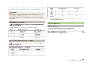 108
108 109
109 110
110 111
111 112
112 113
113 114
114 115
115 116
116 117
117 118
118 119
119 120
120 121
121 122
122 123
123 124
124 125
125 126
126 127
127 128
128 129
129 130
130 131
131 132
132 133
133 134
134 135
135 136
136 137
137 138
138 139
139 140
140 141
141 142
142 143
143 144
144 145
145 146
146 147
147 148
148 149
149 150
150 151
151 152
152 153
153 154
154 155
155 156
156 157
157 158
158 159
159 160
160 161
161 162
162 163
163 164
164 165
165 166
166 167
167 168
168 169
169 170
170 171
171 172
172 173
173 174
174 175
175

