Page 209 of 258
The concentration should be checked before the
start
of cold weather and anti-freeze added to the
system if necessary. Washer fluid
E08402200010
Check
if the fluid level is between the “FULL” and
“1/2” on the washer fluid reservoir.
If the level is low, replenish the container with wash-
er fluid.
FULL NOTE
l The
washer fluid container serves the wind-
screen, rear window.
During cold weather
To ensure proper operation of the washers at low
temperatures, use a fluid containing an anti-freez-
ing agent. Brake fluid
E08406100017
To check the fluid level
The
brake fluid level must be between the “MAX”
and “MIN” marks on the reservoir. The brake fluid level is monitored by a float. When
the
brake fluid level falls below the “MIN” mark,
the brake fluid warning lamp lights up.
The fluid level falls slightly with wear of the brake
pads, but this does not indicate any abnormality.
Vehicle care and Maintenance
8-11 8
OHAE13E1
Page 210 of 258

The brake fluid in the master cylinder should be
checked
when doing other work under the bonnet.
The brake system should also be checked for leak-
age at the same time.
If the brake fluid level falls markedly in a short
length of time, it indicates leaks from the brake sys-
tem.
If this occurs, we recommend you to have the vehi-
cle checked.
Fluid type
Use brake fluid conforming to DOT3 or DOT4
from a sealed container. The brake fluid is hygro-
scopic. Too much moisture in the brake fluid will
adversely affect the brake system, reducing the per-
formance. CAUTION
l
Take
care in handling brake fluid as it is
harmful to the eyes, may irritate your
skin and also damage painted surfaces.
l Use only the specified brake fluid.
Do not mix or add different brands of
brake fluid to prevent chemical reactions.
Do not let any petroleum-based fluid
touch, mix with, or get into the brake fluid.
This will damage the seals.
l Keep the reservoir tank cap closed to pre-
vent the brake fluid from deteriorating ex-
cept maintenance.
l Clean the filler cap before removing and
close the cap securely after maintenance. Auxiliary battery
E08402300011
The
condition of the auxiliary battery is very impor-
tant to keep the vehicle’s electrical system working
properly. Regular inspection and care are especial-
ly important in cold weather.
Removing and installing the auxiliary
battery upper cover E08402400012
To remove 1. Turn
the plastic nut (A) anticlockwise, and
then remove the auxiliary battery upper cov-
er (B). NOTE
l Be
careful not to lose the removed plastic nut. To install
1. Install
the auxiliary battery upper cover (B)
onto the auxiliary battery, and then push the
plastic nut (A) in the direction shown by the
arrows to secure the cover. CAUTION
l
Be sure to install the auxiliary battery up-
per
cover. Otherwise, the battery electro-
lyte may spill and cause a malfunction.
l When installing the auxiliary battery up-
per cover and plastic nut do not touch the
cooling fan or other moving parts in the
bonnet room.
Be especially careful that the cables, your
clothing or hair, etc., do not get caught in
the cooling fan or other moving parts.
NOTE l Be
sure to install the plastic nut in the correct
direction. Vehicle care and Maintenance
8-12
8
OHAE13E1
Page 211 of 258

Checking auxiliary battery electrolyte
level
E08402500013Before checking the auxiliary battery electrolyte lev-
el, remove the auxiliary battery’s upper cover.
The
electrolyte level must be between the specified
limit on the outside of the auxiliary battery. Replen-
ish with distilled water as necessary.
The inside of the auxiliary battery is divided into
several compartments; remove the cap from each
compartment and fill to the upper mark. Do not top
up beyond the upper mark because spillage during
driving could cause damage.
Check the electrolyte level at least once every 4
weeks, depending on the operating conditions.
If the auxiliary battery is not used, it will discharge
by itself with time.
Check it once every four weeks and charge with
low current if necessary. During cold weather
E08402600014
The
capacity of the auxiliary battery is reduced at
low temperatures. This is an inevitable result of its
chemical and physical properties. This is why a
very cold auxiliary battery, particularly one that is
not fully charged will only deliver a fraction of the
starting current which is normally available.
We recommend you to have the auxiliary battery
checked before the start of cold weather and, if nec-
essary, have it charged or replaced.
This does not only ensure reliable starting, but an
auxiliary battery which is kept fully charged also
has a longer life.
Disconnection and connection E08402700015
To disconnect the auxiliary battery cable, stop the
electric
motor unit, first disconnect the negative (-)
terminal and then the positive (+) terminal. When
connecting the auxiliary battery, first connect the
positive (+) terminal and then the negative (-) termi-
nal.
NOTE
l Open the terminal cover (A) before discon-
necting or connecting the positive (+) termi-
nal of the auxiliary battery.
l Loosen the nut (B), and then disconnect the
auxiliary battery cable from the positive (+)
terminal. WARNING
l Keep sparks, cigarettes, and flames away
from the auxiliary battery because the
auxiliary battery could explode.
l When installing the auxiliary battery,
start connection with the positive (+) ter-
minal. If connection is started from the
negative (-) terminal, sparks will occur if
the positive (+) terminal touches any oth-
er parts, and this may cause the auxiliary
battery to explode.
l The auxiliary battery electrolyte is ex-
tremely caustic. Do not allow it to come
in contact with your eyes, skin, clothing,
or the painted surfaces of the vehicle.
Spilt electrolyte should be flushed imme-
diately with ample amounts of water.
Irritation to eyes or skin from contact
with electrolyte requires immediate medi-
cal attention.
l Ventilate when charging or using the aux-
iliary battery in an enclosed space. Vehicle care and Maintenance
8-13 8
OHAE13E1
Page 212 of 258

CAUTION
l
Keep it out of reach of children.
l When
replacing the auxiliary battery, re-
move the connected positive (+) and nega-
tive (-) terminals after turning the electric
motor switch to the “LOCK” position
and waiting at least 1 minute. If the auxil-
iary battery terminal is removed just af-
ter the electric motor switch is turned to
the “LOCK” position, this may cause dam-
age to components of the electric motor
unit.
l Never short-circuit the auxiliary battery.
This could cause it to overheat and be dam-
aged.
l If the auxiliary battery is to be quick-
charged, first disconnect the battery ca-
bles.
l In order to prevent a short circuit, be
sure to disconnect the negative (-) termi-
nal first.
l Always wear protective eye goggles when
working near the auxiliary battery.
l Do not bring the nearby parts, the plastic
parts and so on into contact with sulphu-
ric acid (battery electrolyte) which may
crack, stain or discolour them.
If they are in contact, wipe off with soft
cloth, chamois or the like and an aqueous
solution of neutral detergent then imme-
diately rinse the affected parts with plen-
ty of water. NOTE
l Keep
the terminals clean. After the auxiliary
battery is connected, apply terminal protec-
tion grease. To clean the terminals, use luke-
warm water.
l Check to see if the auxiliary battery is secure-
ly installed and cannot be moved during trav-
el. Also check each terminal for tightness.
l When the vehicle is to be left unused for a
long period of time, remove the auxiliary bat-
tery and store it in a place where the battery
fluid will not freeze. The auxiliary battery
should be stored only in a fully charged con-
dition.
l It is necessary to adjust the electronic control-
led unit when the auxiliary battery is re-
moved for a long period of time.
Consult a MITSUBISHI MOTORS Author-
ized Service Point. Tyres
E08402800016 WARNING
l Driving
with tyres that are worn, dam-
aged or improperly inflated can lead to
loss of control or blowout of the tyres
which can result in a collision with seri-
ous or fatal injury. Vehicle care and Maintenance
8-14
8
OHAE13E1
Page 213 of 258
Tyre inflation pressures
E08402900033Tyre size Front Rear
145/65R15 2.5 bar (36 psi) [250 kPa] —
175/55R15 —2.5 bar (36 psi) [250 kPa]Check the tyre inflation pressure of all the tyres while they are cold; if insufficient or excessive, adjust to the specified value.
After the tyre inflation pressure has been adjusted, check the tyres for damage and air leaks. Be sure to put caps on the valves. Vehicle care and Maintenance
8-15 8
OHAE13E1
Page 214 of 258

Wheel condition
E084030000151- Location of the tread wear indicator
2-
Tread wear indicator
Check the tyres for cuts, cracks and other damage.
Replace the tyres if there are deep cuts or cracks.
Also check each tyre for pieces of metal or pebbles.
The use of worn tyres can be very dangerous be-
cause of the greater chance of skidding or hydro-
planing. The tread depth of the tyres must exceed
1.6 mm in order for the tyres to meet the minimum
requirement for use.
Tread wear indicators will appear on the surface of
the tyre as the tyre wears, thereby indicating that
the tyre no longer meets the minimum requirement
for use. When these wear indicators appear, the
tyres must be replaced with new ones. CAUTION
l
Always
use tyres of the same size, same
type, and same brand, and which have no
wear differences. Using tyres of different
size, type, brands or degree of wear, will
increase the differential oil temperature,
resulting in possible damage to the driv-
ing system. Further, the drive train will
be subjected to excessive loading, possibly
leading to oil leakage, component seizure,
or other serious faults.
Replacing tyres and wheels E08403100016 CAUTION
l
Avoid
using different size tyres from the
one listed and the combined use of differ-
ent types of tyres, as this can affect driv-
ing safety. Refer to “Tyres and wheels”
on page 9-06.
l Even if a wheel has the same rim size and
offset as the specified type of wheel, its
shape may prevent it from being fitted cor-
rectly. We recommend you to consult a
specialist before using wheels that you
have. Tyre rotation
E08403200017
Because
the front and rear tyres and wheels are not
the same size, front and rear tyre rotation is not pos-
sible. *: Front
WARNING
l Rotating tyres would compromise the sta-
bility
and drivability of the vehicle and
could lead to a serious accident.
Snow tyres E08403300018
The use of snow tyres is recommended for driving
on
snow and ice. To preserve driving stability,
mount snow tyres of the same size and tread pat-
tern on wheels.
A snow tyre that is worn down more than 50% is
no longer appropriate to use.
Snow tyres which do not meet specifications must
not be used. Vehicle care and Maintenance
8-16
8
OHAE13E1
Page 215 of 258

CAUTION
l
Observe permissible maximum speed for
your snow tyres and the legal speed limit.
NOTE l The
laws and regulations concerning snow
tyres (driving speed, required use, type, etc.)
vary. Find out and follow the laws and regu-
lations in the area you intend to drive.
l If flange nuts are used on your vehicle,
change to tapered nuts when steel wheels are
used.
Tyre chains E08403400035
If tyre chains have to be used, ensure that they are
fitted
only on the drive wheels (rear) in accordance
with the manufacturer’s instructions.
Use only tyre chains which are designed for use
with the tyres mounted on the vehicle: use of the in-
correct size or type of chain could result in damage
to the vehicle body.
Contact a MITSUBISHI MOTORS Authorized
Service Point before putting on tyre chains. The
max. chain height is as follows. Tyre size Wheel size Max chain
height[mm]
175/55R15 15 x 5 J 14 mm When driving with tyre chains on the tyres, do not
drive
faster than 50 km/h (30 mph). When you
reach roads that are not covered in snow, immedi-
ately remove the tyre chains. CAUTION
l
Practice
fitting the chains before you
need them. Don’t expect help from other
people in the cold.
l Choose a clear straight stretch of road
where you can pull over and still be seen
while you are fitting the chains.
l Do not fit chains before you need them.
This will wear out your tyres and the
road surface.
l After driving around 100-300 metres,
stop and retighten the chains.
l Drive carefully and do not exceed
50 km/h (30 mph). Remember that pre-
venting accidents is not the purpose of
tyre chains.
l An aluminium wheel can be damaged by
a tyre chain while driving. When fitting a
tyre chain on an aluminium wheel, take
care that no part of the chain and fitting
can be brought into contact with the wheel.
l When installing or removing the tyre
chains, take care that hands and other
parts of your body are not injured by the
sharp edges of the vehicle body.
NOTE l The
laws and regulations concerning the use
of tyre chains vary. Always follow local laws
and regulations.
In most countries, it is prohibited by law to
use tyre chains on roads without snow. Wiper blades
E08403500010
If
the blades are frozen to the windscreen or rear
window, do not operate the wipers until the ice has
melted and the blades are freed, otherwise the wip-
er motor may be damaged.
NOTE
l When replacing the front wiper with a wiper
for use in cold regions, it is necessary to ad-
just the washer nozzle spray positions. Al-
ways contact your MITSUBISHI MOTORS
Authorized Service Point when replacing the
front wiper with a wiper for use in cold re-
gions.
l When removing snow and frost, be careful
not to damage the washer nozzles (A) attach-
ed to the wiper arm. Wiper blade rubber replacement
Windscreen wiper blades
1.
Lift the wiper arm off the windscreen.
2. Pull the wiper blade until its stopper (A) dis- engages from the hook (B) as indicated direc- Vehicle care and Maintenance
8-17 8
OHAE13E1
Page 216 of 258

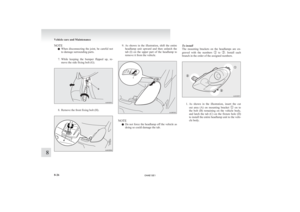
tion by the arrow (C) on the hook. Pull the
wiper blade to remove it.
NOTE
l Do
not let the wiper arm drop onto the wind-
screen. This could damage the glass. 3. Attach
the retainers (D) to a new wiper
blade. Refer to the illustration to ensure that
the retainers are correctly aligned as you at-
tach them. 4. Insert
the wiper blade into the arm, starting
with the opposite end of the blade from the
stopper. Make sure the hook (B) is fitted cor-
rectly in the grooves in the blade.
NOTE l If a retainer is not supplied with the new wip-
er blade, use the retainer from the old blade. 5. Push
the wiper blade until the hook (B) en-
gages securely with the stopper (A). Rear window wiper blades
1.
Lift the wiper arm off the window glass.
2. Pull the wiper blade downward to disengage it from the stopper (A) at the end of the wip-
er arm. Pull the wiper blade further to re-
move it.
3. Slide a new wiper blade through the hook (B) on the wiper arm. Vehicle care and Maintenance
8-18
8
OHAE13E1