Page 345 of 364

R20
Tires Alloyw
heels V1 V2
BA: 265/45 R20 108 H XL
M+Si
20 BA: 9.0 J x 20 H2
Wheel offset: 2.36 in (60 mm) #
—
Emergency spare wheel
Important safety notes
G
WARNING
The wheel or tire size as well as the tire type
of the spare wheel or emergency spare wheel
and the wheel to be replaced may differ.
Mounting an emergency spare wheel may
severely impair the driving characteristics.
There is a risk of an accident.
To avoid hazardous situations:
R adapt yourd riving style accordingly and
drive carefully.
R never install more than one spare wheel or
emergency spare wheel that differs in size.
R only use a spare wheel or emergency spare
wheel of a different size briefly.
R do not switch ESP ®
off.
R have a spare wheel or emergency spare
wheel of a different size replaced at the
nearest qualified specialist workshop.
Observe that the wheel and tire dimensions
as well as the tire type must be correct.
When using an emergency spare wheel or
spare wheel of a different size, you must not
exceed the maximum speed of 50 mph
(80 km/h).
Snow chains must not be mounted on
emergency spare wheels. General notes
Mounting the emergency spare wheel is
described under "Mounting a wheel"
(Y page 335). An emergency spare wheel may also be
mounted against the direction of rotation.
Observe the time restriction on use as well as
the speed limitation specified on the
emergency spare wheel.
Replace the tires after six years at the latest,
regardless of wear. This also applies to the
emergency spare wheel.
Removing the emergency spare wheel
The collapsible spare wheel can be found in
the stowage well under the cargo
compartment floor.
X
Lift the cargo compartment floor up
(Y page 298).
X Remove the jack from the tool holder.
X Turn retaining screw :counter-clockwise
and out of tool holder =and remove it.
i If retaining screw :does not come out
immediately, turn tool holder =slightly
counter-clockwise.
Retaining screw :can then be unscrewed
with ease.
20 Use of snow chains not permitted. Observe the notes under "Snow chains". 342
Emergency spare wheelWheels and tires
Page 346 of 364

X
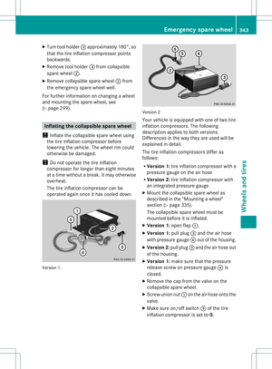
Turn tool holder =approximately 180°, so
that the tire inflation compressor points
backwards.
X Remove tool holder =from collapsible
spare wheel ;.
X Remove collapsible spare wheel ;from
the emergency spare wheel well.
For further information on changing a wheel
and mounting the spare wheel, see
(Y page 299). Inflating the collapsible spare wheel
! Inflate the collapsible spare wheel using
the tire inflation compressor before
lowering the vehicle. The wheel rim could
otherwise be damaged.
! Do not operate the tire inflation
compressor for longer than eight minutes
at a time without a break. It may otherwise
overheat.
The tire inflation compressor can be
operated again once it has cooled down. Version 1 Version 2
Your vehicle is equipped with one of two tire
inflation compressors. The following
description applies to both versions.
Differences in the way they are used will be
explained in detail.
The tire inflation compressors differ as
follows:
R
Version 1: tire inflation compressor with a
pressure gauge on the air hose
R Version 2: tire inflation compressor with
an integrated pressure gauge
X Mount the collapsible spare wheel as
described in the "Mounting a wheel"
section (Y page 335).
The collapsible spare wheel must be
mounted before it is inflated.
X Version 1: open flap:.
X Version 1: pull plug=and the air hose
with pressure gauge ?out of the housing.
X Version 2: pull plug=and the air hose out
of the housing.
X Version 1: make sure that the pressure
release screw on pressure gauge ?is
closed.
X Remove the cap from the valve on the
collapsible spare wheel.
X Screw union nut :on the air hose onto the
valve.
X Make sure on/of fswitch Aof the tire
inflatio ncompressor is set to 0. Emergency spare wheel
343Wheels and tires Z
Page 347 of 364

X
Insert plug 3into the socket in the
footwell of the second row of seats
(Y page 270).
Only operate the tire inflatio ncompressor
using the socket in the footwell of the
second row of seats (Y page 270), even if
the ignition is turned off.
An emergency cut-out ensures that the on-
board voltage does not drop too low. If the
on-board voltage is too low, the power to
the sockets is automatically cut. This
ensures that there is sufficient power to
start the engine.
X Turn the SmartKey to position 1in the
ignition lock (Y page 149).
X Press on/offs witch;on the tire inflation
compressor to I.
The tire inflatio ncompressor is switched
on. The tire is inflated. The tire pressure is
shown on pressure gauge ?.
X Inflate the tire to the specified tire
pressure.
The specified tire pressure is printed on the
yellow label of the emergency spare wheel.
X When the specified tire pressure has been
reached, press on/offs witch2on the
electric air pump to 0.
The tire inflatio ncompressor is switched
off.
X Turn the SmartKey to position 0in the
ignition lock.
X Version 1: if the tire pressure is higher than
specified, open the pressure release screw
on pressure gauge 4until the correct tire
pressure is set.
X Version 2: if the tire pressure is higher than
specified, press pressure release button
6 until the correct tire pressure is set.
X Unscrew union nut Aon the air hose from
the valve.
X Screw the valve cap ontot he collapsible
spare wheel valve again.
X Version 1:s tow plug=and the ai rhose
behind flap :. X
Version 2:s tow plug=and the ai rhose
in the lower section of the compressor
housing.
X Stow the tire inflation compressor in the
vehicle. Stowing the emergency sparew
heel
! Only place the collapsible spare wheel in
the vehicle whe nitis dry. Otherwise,
moisture may get into the vehicle.
Take the following steps to stow a used
collapsible spare wheel. It will not otherwise
fit into the spare wheel well.M ercedes-Benz
recommends that you have this work
performed at a qualified specialist workshop,
e.g. at an authorized Mercedes-BenzC enter.
X Unscrew the valve cap from the valve.
X If possible, unscrew the valve insert from
the valve and release the air.
i Fully deflating the tires can take a few
minutes.
X Screw the valve insert back into the valve.
X Screw the valve cap back on. 344
Emergency spare wheelWheels and tires
Page 348 of 364
:
Guides
; Collapsible spare wheel
In the spare wheel well, there are two
guides :to keep the collapsible spare wheel
in place.
X Lay collapsible spare wheel ;in the
emergency spare wheel well.
i Make sure that collapsible spare
wheel ;is positioned on guides :
precisely.
X Lay the tool holde rincollapsible spare
wheel ;so that the tire inflation
compressor is pointing towards the tailgate
(Y page 298).
X Turn tool holder approximately 180° so
that the tire inflation compressor points
forwards.
The tool holder should now be positioned
as stated in the instructions regarding the
installation position. X
Turn the retainer screw on the collapsible
spare wheel clockwise into the tool holder
as far as it will go.
X Stow the jack in the vehicle tool kit. Emergency spare wheel
345Wheels and tires Z
Page 349 of 364
Technical data
R3 50 BlueEFFICIENCY Collapsible spare wheel
Tires Alloy wheels
195/75 – 18 106 P
Tire pressure: 300 kPa (3.0 bar/44 psi) 6.5 B x 18 H2
Wheel offset: 1.58 in (40 mm)
i
The R 350 BlueTEC 4MATIC model is not equipped with a collapsible spare wheel. 346
Emergency spare wheelWheels and tires
Page 350 of 364
Useful information
............................348
Information regarding technical
data .................................................... 348
Genuine Mercedes-Benz parts .........348
Warranty ............................................ 348
Identification plates .........................349
Service products and filling capaci-
ties ..................................................... 350
Vehicle data ...................................... 357 347Technical data
Page 351 of 364

Useful information
i This Operator's Manual describes all
models and all standard and optional
equipment of your vehicle available at the
time of publication of the Operator's
Manual. Country-specific differences are
possible. Please note that your vehicle may
not be equipped with all features
described. This also applies to safety-
related systems and functions.
i Read the information on qualified
specialist workshops: (Y page 24).Information regarding technical data
i The data stated here specifically refers to
a vehicle with standard equipment .Consult
an authorized Mercedes-Benz Center for
the data for all vehicle variants and trim
levels. Genuine Mercedes-Benz parts
G
WARNING
Driving safety may be impaired if non-
approved parts, tires and wheels or safety-
relevant accessories are used.
This could lead to malfunctions in safety-
relevant systems, e.g. the brake system. This
could cause you to lose control of your vehicle
and cause an accident.
For this reason, Mercedes-Benz recommends
that you use genuine Mercedes-Benz parts or
parts of equal quality. Only use tires, wheels
and accessories that have been specifically
approved for your vehicle. H
Environmental note
Daimler AG also supplies reconditioned major
assemblies and parts which are of the same
quality as new parts. They are covered by the
same Limited Warranty entitlements as new
parts. !
Air bags and Emergency Tensioning
Devices, as well as control units and
sensors for these restraint systems, may be
installed in the following areas of your
vehicle:
R doors
R door pillars
R door sills
R seats
R cockpit
R instrument cluster
R center console
Do not install accessories such as audio
systems in these areas. Do not carry out
repairs or welding. You could impair the
operating efficiency of the restraint
systems.
Have aftermarket accessories installed at
a qualified specialist workshop.
Genuine Mercedes-Benz parts are subject to
strictq uality control .Each part has been
specially developed, manufactured or
selected for Mercedes-Ben zvehicles and
fine-tuned for them. Only genuine Mercedes-
Benzp arts should therefor ebe used.
More than 300,000 different genuine
Mercedes-Benzp arts are available for
Mercedes-Ben zmodels.
All authorized Mercedes-Benz Centers
maintain a supply of genuine Mercedes-Benz
parts for necessary service and repair work.
In addition, strategically located parts
delivery centers provide quick and reliable
parts service.
Always specify the vehicle identification
number (VIN) (Y page 349) and the engine
number (Y page 350) when ordering genuine
Mercedes-Benz parts. Warranty
Your vehicle is covered under the terms of the
warranties printed in the Service and
Warranty Information booklet. 348
WarrantyTechnical data
Page 352 of 364

Your authorized Mercedes-Ben
zCenter will
replace and repair all factory-installed parts
in accordance with the following warranty
terms and conditions:
R New Vehicle Limited Warranty
R Emission Systems Warranty
R Emission Performance Warranty
R California, Connecticut, Maine,
Massachusetts, New York, Pennsylvania,
Rhode Island and Vermon tEmission
Control System Warranty (only for vehicles
with a gasoline engine)
R State warranty enforcement laws (Lemon
Laws)
Replacement parts and accessories are
covered by the Mercedes-Benz Parts and
Accessories warranties. These are available
at any authorized Mercedes-Benz Center.
i If you lose the Service and Warranty
Information booklet, contact an authorized
Mercedes-Benz Center to arrange a
replacement. It will be mailed to you. Identification plates
Vehicle identification plate with
vehicle identification number (VIN)
X
Open the driver's door.
You will see vehicle identification plate :. Example: vehicle identification plate (USA only)
Example: vehicle identification plate (Canada only)
;
Paint code
= VIN
i The data show nonthe vehicle
identification plate is used only as an
example. This data is different for every
vehicle and can deviate from the data
shown here. You can find the data
applicable to your vehicle on the vehicle's
identification plate. VIN Identification plates
349Technical data Z