Page 161 of 352

wear over time through normal use, are specifically not
covered (replacement foam is available for a nominal
charge). UNWIRED TECHNOLOGY IS NOT LIABLE
FOR ANY INJURIES OR DAMAGES TO PERSONS
OR PROPERTY RESULTING FROM THE USE OF, OR
ANY FAILURE OR DEFECT IN, THE PRODUCT,
NOR IS UNWIRED LIABLE FOR ANY GENERAL,
SPECIAL, DIRECT, INDIRECT, INCIDENTAL, CON-
SEQUENTIAL, EXEMPLARY, PUNITIVE OR OTHER
DAMAGES OF ANY KIND OR NATURE WHATSO-
EVER. Some states and jurisdictions may not allow the
exclusion or limitation of incidental or consequential
damages, so the above limitation may not apply to you.
This warranty gives you specific legal rights. You may
also have other rights, which vary from jurisdiction to
jurisdiction.
What Will Unwired
®Do?Unwired
®, at its option,
will repair or replace any defective Product. Unwired
®
reserves the right to replace any discontinued Product
with a comparable model. THIS WARRANTY IS THE
SOLE WARRANTY FOR THIS PRODUCT, SETS
FORTH YOUR EXCLUSIVE REMEDY REGARDING
DEFECTIVE PRODUCTS, AND IS IN LIEU OF ALL
OTHER WARRANTIES (EXPRESS OR IMPLIED), IN-
CLUDING ANY WARRANTY OR MERCHANTABIL-
ITY OR FITNESS FOR A PARTICULAR PURPOSE. Video Screen Operation
Displaying Video
The video screen has two different operating modes, a
video mode (when displaying video such as DVD video,
Aux video, etc.) and an information mode. Because the
VES™ is a dual channel system, Information Mode is
displayed in a split screen format. When in Information
Mode, the left side of the screen is referred to as
Channel 1 and the right side of the screen is referred to
as Channel 2.
Only Channel 1 displays video images. When in video
mode the image is displayed on the full screen, however
Channel 2’s functionality is still available. A popup
banner at the bottom of the screen is displayed mo-
mentarily over the video image. While in video mode
and Channel 2 is selected on the remote control
selector switch, the first remote control key press will
activate the popup banner indicating Channel 2’s sta-
tus. While the banner is still visible, any subsequent
remote control key press for Channel 2 shall initiate
the requested remote control command. (fig. 110)
In a two-screen system, the video for Channel 1 is
displayed on the first rear seat screen and the video for
Channel 2 is displayed on the second rear seat screen.
Information Mode is displayed in split screen, the left
side of the screen (Channel 1) shows the status/mode
of the first rear seat screen and the right side of the
155
KNOWING
YOUR
VEHICLE
SAFETY
S
TARTING
AND
DRIVING
WARNING
LIGHTS
AND
MESSAGES
IN AN
EMERGENCY
SERVICING
AND
CARETECHNICAL
SPECIFICATIONSCONTENTS
Page 162 of 352

screen (Channel 2) shows the status/mode of the
second rear seat screen.
When Channel 1 is in a video mode, the image is
displayed on the first rear seat screen as a full screen
image. A popup banner at the bottom of the screen is
displayed momentarily over the video image showing
any change in status of Channel 2.
When Channel 2 is in video mode, the image is dis-
played on the second rear seat screen as a full screen
image. A popup banner at the bottom of the screen is
displayed momentarily over the video image showing
any change in status of Channel 1.Playing A Disc On The VES™
The following actions occur automatically when a disc
is inserted into the radio on a single screen system and
into the remote DVD player on a two screen system:
If the video screen is in the open position (the LCD
screen is visible), then the screen turns on and the
wireless headphone transmitter turns on. If the video
screen is closed, the wireless headphone transmitter
must be turned on by using the power button on the
remote control (headphones only receive audio sig-
nals if the headphones are powered on).
After the disc is inserted, the disc begins playing to cabin speakers, wireless headphones, and rear video
screens.
Shared Modes
The VES™ and radio are capable of communicating
with each other. This allows the VES™ to output radio
audio to the headphones and the radio to output
VES™ audio to the vehicle speakers. When the radio
and VES™ are in the same (shared) mode, a VES™ icon
will be visible on the radio’s display and the shared icon
will be visible on the VES™ screen. When in shared
mode, the same audio source is heard in the head-
phones and vehicle speakers simultaneously.
If the radio functions (FM, AM, or SAT) are in the
shared mode with the VES™, only the radio is able to(fig. 110) Popup Banner
156
KNOWING YOUR
VEHICLE
SAFETY
S
TARTING AND
DRIVING
WARNING LIGHTSAND
MESSAGES
IN AN
EMERGENCY
SERVICING AND
CARETECHNICAL
SPECIFICATIONSCONTENTS
Page 163 of 352

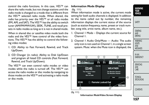
control the radio functions. In this case, VES™ can
share the radio mode, but not change stations until the
radio mode is changed to a mode that is different from
the VES™ selected radio mode. When shared, the
radio has priority over the VES™ or all radio modes
(FM, AM, and SAT). The VES™ has the ability to switch
tuner (AM/FM/MW/LW), SEEK, TUNE, and recall pre-
sets in radio modes as long as it is not in shared mode.
When in shared disc or satellite video mode both the
radio and the VES™ have control of the video func-
tions. The VES™ has the ability to control the follow-
ing video modes:
1. CD: Ability to Fast Forward, Rewind, and TrackUp/Down.
2. CD Changer (in radio): Ability to Disk Up/Down and program all listed CD controls (Fast Forward,
Rewind, and Track Up/Down).
The VES™ can even control radio modes or video
modes while the radio is turned off. The VES™ can
access the radio modes or disc modes by navigating to
those modes on the VES™ and activating a radio mode
or disc mode. Information Mode Display
(fig. 111)
When information mode is active, the current mode
setting for both audio channels is displayed. In addition
to the items called out by number, the remaining
information displays the current status of the source
(such as station frequency, name, preset or track num-
ber, song title, artist name, album name, etc.).
1. Channel 1 Mode – Displays the current source for
Channel 1.
2. Channel 1 Audio Only/Mute — Audio: The audio only icon is not used on Channel 1, in a single screen
system. Mute: when the Mute icon is displayed, the
(fig. 111) Information ModeVideo Screen Display
157
KNOWING
YOUR
VEHICLE
SAFETY
S
TARTING
AND
DRIVING
WARNING
LIGHTS
AND
MESSAGES
IN AN
EMERGENCY
SERVICING
AND
CARETECHNICAL
SPECIFICATIONSCONTENTS
Page 164 of 352

audio for Channel 1 has been muted using the
remote control’s MUTE button.
3. Channel 2 Audio Only/Mute — Audio: Only in a single screen system: The audio only icon is dis-
played on Channel 2 when Channel 1 is in a video
mode. Mute: when the Mute icon is displayed, the
audio for Channel 2 has been muted using the
remote control’s MUTE button.
4. Channel 2 Mode — Displays the current source for Channel 2.
5. Channel 2 ENTER Button Action — When the ENTER button on the remote control is pressed
with the "INPUT FILE #" button visible on the
screen, the screen shows a numeric entry keypad
which allows you to enter a specific track number
on data discs and HDD (see Numeric Keypad Menu
section of this manual). Also, Enter Button Action –
“INPUT TRK #” to enter a specific track number on
audio discs.
6. Remote Locked Out — When the icon is displayed, the remote control functions are disabled.
7. Clock — Displays the time.
8. Channel 1 Shared Status — When the icon is displayed, the audio for Channel 1 is also shared
with the radio and playing through the cabin speak-
ers. Mode Selection Menu
(fig. 112)
The first press of the MODE button causes the Mode
Selection menu to appear on screen. The current mode
is always the default selection. The mode can be
changed for either Channel/Screen 1 or Channel/
Screen 2 using the remote control.
Use the remote control’s navigation buttons (▴, ▾,▸,◂)
to navigate through the available modes, and then press
the remote control’s ENTER button to select the
mode. An alternate method of changing modes is
repeated pressing of the MODE button until the de-
sired mode is highlighted then press the ENTER button
on the remote control to select the mode.
(fig. 112) Mode Selection Menu
158
KNOWING YOUR
VEHICLE
SAFETY
S
TARTING AND
DRIVING
WARNING LIGHTSAND
MESSAGES
IN AN
EMERGENCY
SERVICING AND
CARETECHNICAL
SPECIFICATIONSCONTENTS
Page 165 of 352

In a single screen system, when a video mode (such as
DVD-video, Aux video, etc.) is active and Channel/
Screen 1 is selected using the remote control selector
switch, the first press of the remote control’s MODE
button causes the Mode Selection menu to appear.
Numeric Keypad Menu(fig. 113)
When the display for either Channel 1 or Channel 2
shows a direct action button, pressing the remote
control’s ENTER button activates a numeric keypad
menu. This screen makes it easy to enter a specific
tuner frequency, satellite channel, or track number. To
enter the desired digit: 1. Press the remote control’s navigation buttons (▴,
▾,
▸, ◂) to navigate to the desired digit.
2. When the digit is highlighted, press the remote control’s ENTER button to select the digit. Repeat
these steps until all digits are entered.
3. To delete the last digit, navigate to the Del button and press the remote control’s ENTER button.
4. After all of the digits are entered, navigate to the Go button and press the remote control’s ENTER but-
ton.
Disc Menu
When listening to a CD Audio or CD Data disc,
pressing the remote control’s MENU button displays a
list of all commands which control playback of the disc.
Using the options you can activate or cancel play and
Random play.
Display Settings (fig. 114)
When watching a video source (DVD Video with the
disc in Play mode, Aux Video, etc.), pressing the re-
mote control’s SETUP button activates the Display
Settings menu. These settings control the appearance
of the video on the screen. The factory default settings
are already set for optimum viewing, so there is no
need to change these settings under normal circum-
stances.(fig. 113) Numeric Keypad Menu
159
KNOWING
YOUR
VEHICLE
SAFETY
S
TARTING
AND
DRIVING
WARNING
LIGHTS
AND
MESSAGES
IN AN
EMERGENCY
SERVICING
AND
CARETECHNICAL
SPECIFICATIONSCONTENTS
Page 166 of 352

To change the settings, press the remote control’s
navigation buttons (▴,▾) to select an item, then press
the remote control’s navigation buttons (▸, ◂) to
change the value for the currently selected item. To
reset all values back to the original settings, select the
Default Settings menu option and press the remote
control’s ENTER button.
Disc Features control the remote DVD player's (for
versions/markets, where provided) settings of DVD
being watched in the remote player.
Listening To Audio With The Screen Closed
To listen to only audio portion of the channel with the
screen closed:
Set the audio to the desired source and channel. Close the video screen.
To change the current audio mode, press the remote
control’s MODE button. This will automatically se-
lect the next available audio mode without using the
Mode Select menu.
When the screen is reopened, the video screen will automatically turn back on and show the appropriate
display menu or media.
If the screen is closed and there is no audio heard,
verify that the headphones are turned on (the ON
indicator is illuminated) and the headphone selector
switch is on the desired channel. If the headphones are
turned on, press the remote control’s power button to
turn audio on. If audio is still not heard, check that fully
charged batteries are installed in the headphones.
Why Does The Screen Mode Change
Automatically?
In order to make the operation of the VES™ simple
and with the least amount of driver distraction, specific
events will cause the screen(s) to automatically switch
to DVD mode. These events are:
Loading a disc in the DVD player (if so equipped),
Pressing the PLAY button on the DVD player face- plate when the disc is stopped or paused, or
AM/FM band selection via Radio.(fig. 114) Video Screen Display Settings
160
KNOWING YOUR
VEHICLE
SAFETY
S
TARTING AND
DRIVING
WARNING LIGHTSAND
MESSAGES
IN AN
EMERGENCY
SERVICING AND
CARETECHNICAL
SPECIFICATIONSCONTENTS
Page 167 of 352

If your vehicle is not equipped with the separate DVD
player, the following events in the Radio will cause the
screen(s) to automatically switch to Radio Disc mode.
Loading a disc in the radio CD/DVD player
AM/FM band selection via Radio
Auxiliary Inputs
For each video screen there is an auxiliary (Aux jack)
device input which is used to connect external audio/
video sources to the VES™. Examples of devices that
can be connected to the Aux inputs include portable
music players, video cameras, VCR’s, game systems,
and other devices with audio and/or video outputs.
The Aux jacks are typically located on the back of the
center console or on one of the vehicles side panels in
the rear occupant area.(fig. 115) When connecting an external source to the AUX
input, be sure to follow the standard color coding for
the VES™ jacks:
1. Video in (yellow)
2. Left audio in (white)
3. Right audio in (red)
Using The Auxiliary Audio/Video Input Jacks
(AUX)
Lower the screen or press the POWER button on
the remote control to turn the screen on.
Plug the Audio and/or Video outputs from the exter- nal device with volume turned up into the AUX jack
(make sure to match up the color coding: Video is
Yellow, Left Audio is White, and Right Audio is Red).
Then navigate to VES AUX1 or VES AUX2 mode in
the Select Mode screen.
To exit out of AUX mode, use the MODE button on the remote control to navigate out of AUX mode.
(Refer to the instructions in the Mode Selection
Menu section of this manual).(fig. 115)
161
KNOWING
YOUR
VEHICLE
SAFETY
S
TARTING
AND
DRIVING
WARNING
LIGHTS
AND
MESSAGES
IN AN
EMERGENCY
SERVICING
AND
CARETECHNICAL
SPECIFICATIONSCONTENTS
Page 168 of 352

iPod®/USB/MP3 CONTROL (for
version/markets where provided)
This feature allows an iPod
®or external USB device to
be plugged into the USB port.
iPod
®
control supports Mini, 4G, Photo, Nano, 5G
iPod
®
and iPhone
®
devices. Some iPod
®
software
versions may not fully support the iPod®
control
features. Please visit Apple’s website for software up-
dates.
For further information, refer to the Uconnect
Touch™ User’s Manual. CD/DVD DISC MAINTENANCE
To keep a CD/DVD in good condition, take the follow-
ing precautions:
1. Handle the disc by its edge; avoid touching the
surface.
2. If the disc is stained, clean the surface with a soft cloth, wiping from center to edge.
3. Do not apply paper or tape to the disc; avoid scratching the disc.
4. Do not use solvents such as benzene, thinner, clean- ers, or anti-static sprays.
5. Store the disc in its case after playing.
6. Do not expose the disc to direct sunlight.
7. Do not store the disc where temperatures may become too high.
NOTE: If you experience difficulty in playing a par-
ticular disc, it may be damaged (i.e., scratched, reflec-
tive coating removed, a hair, moisture or dew on the
disc) oversized, or have protection encoding. Try a
known good disc before considering disc player ser-
vice.
162
KNOWING YOUR
VEHICLE
SAFETY
S
TARTING AND
DRIVING
WARNING LIGHTSAND
MESSAGES
IN AN
EMERGENCY
SERVICING AND
CARETECHNICAL
SPECIFICATIONSCONTENTS