Page 129 of 352

other factors, such as road conditions, leaving the
roadway, or striking objects or other vehicles.
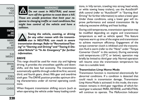
WARNING!
Many factors, such as vehicle loading,
road
conditions, and driving conditions,
influence the chance that wheel lift or rollover
may occur. ERM cannot prevent all wheel lift or
rollovers, especially those that involve leaving the
roadway or striking objects or other vehicles.The
capabilities of an ERM-equipped vehicle must
never be exploited in a reckless or dangerous
manner, which could jeopardize the user's safety
or the safety of others.
ELECTRONIC STABILITY CONTROL (ESC)
This system enhances directional control and stability
of the vehicle under various driving conditions. ESC
corrects for over-steering and under-steering the ve-
hicle by applying the brake of the appropriate wheel.
Engine power may also be reduced to help the vehicle
maintain the desired path.
The ESC uses sensors in the vehicle to determine the
path that the driver intends to steer the vehicle and
compares it to the actual path of the vehicle. When the
actual path does not match the intended path, the ESC
applies the brake of the appropriate wheel to assist in counteracting the condition of over-steer or under-
steer.
Over-steer - when the vehicle is turning more than
appropriate for the steering wheel position.
Under-steer - when the vehicle is turning less than appropriate for the steering wheel position.
WARNING!
Elect
ronic Stability Control (ESC)
cannot prevent the natural laws of phys-
ics from acting on the vehicle, nor can it increase
the traction afforded by prevailing road condi-
tions.
ESC cannot prevent collisions, including those
resulting from excessive speed in turns, driving on
very slippery surfaces, or hydroplaning. ESC also
cannot prevent collisions resulting from the loss
of vehicle control due to inappropriate driver
input for the conditions. Only a safe, attentive,
and skillfull driver can prevent collisions.
The capabilities of an ESC equipped vehicle
must never be explained in a reckless or danger-
ous manner which could jeopardize the user's
safety or the safety of others.
123
KNOWING
YOUR
VEHICLE
SAFETY
STARTING
AND
DRIVING
WARNING
LIGHTS
AND
MESSAGES
IN AN
EMERGENCY
SERVICING
AND
CARETECHNICAL
SPECIFICATIONSCONTENTS
Page 130 of 352

ESC Operating Modes
The ESC system has two available operating modes.
Full On
This is the normal operating mode for ESC. Whenever
the vehicle is started the system will be in this mode.
This mode should be used for most driving situations.
ESC should only be turned to “Partial Off ” for specific
reasons as noted. Refer to “Partial Off ” for additional
information.
Partial Off
The “ESC OFF” button is located in the switch bank
above the climate control. To enter the “Partial Off ”
mode, momentarily press the “ESC OFF” button and
the “ESC Activation/Malfunction Indicator Light” will
illuminate. To turn the ESC on again, momentarily
press the “ESC OFF” button and the “ESC Activation/
Malfunction Indicator Light” will turn off. This will
restore the normal “ESC On” mode of operation.
(fig. 100)NOTE:
To improve the vehicle's traction when driv-
ing with snow chains, or when starting off in deep
snow, sand, or gravel, it may be desirable to switch to
the “Partial Off ” mode by momentarily pressing the
“ESC OFF” button. Once the situation requiring “Par-
tial Off ” mode is overcome, turn ESC back on by
momentarily pressing the “ESC OFF” button. This may
be done while the vehicle is in motion.
(fig. 100) ESC OFF Button
124
KNOWING YOUR
VEHICLE
SAFETY
S
TARTING AND
DRIVING
WARNING LIGHTSAND
MESSAGES
IN AN
EMERGENCY
SERVICING AND
CARETECHNICAL
SPECIFICATIONSCONTENTS
Page 131 of 352

WARNING!
When in “Partial Off ” mode, the TCS
fun
ctionality of ESC (except for the lim-
ited slip feature described in the TCS section) has
been disabled and the “ESC Off Indicator Light”
will be illuminated. All other stability features of
ESC function normally. When in “Partial Off ”
mode, the engine power reduction of TCS is dis-
abled, and the enhanced vehicle stability offered
by the ECS system is reduced.
ESC ACTIVATION/MALFUNCTION
INDICATOR LIGHT AND ESC OFF
INDICATOR LIGHT
The “ESC Activation/Malfunction Indicator
Light” in the instrument cluster will come on
when the ignition switch is turned to the ON
position. It should go out with the engine
running. If the “ESC Activation/Malfunction Indicator
Light” comes on continuously with the engine running,
a malfunction has been detected in the ESC system. If
this light remains on after several ignition cycles, and
the vehicle has been driven several kilometers at
speeds greater than 48 km/h, see your authorized
dealer as soon as possible to have the problem diag-
nosed and corrected. The “ESC Activation/Malfunction Indicator Light” (lo-
cated in the instrument cluster) starts to flash as soon
as the tires lose traction and the ESC system becomes
active. The “ESC Activation/Malfunction Indicator
Light” also flashes when TCS is active. If the “ESC
Activation/Malfunction Indicator Light” begins to flash
during acceleration, ease up on the accelerator and
apply as little throttle as possible. Be sure to adapt your
speed and driving to the prevailing road conditions.
NOTE:
The “ESC Activation/Malfunction Indicator Light”
and the “ESC OFF Indicator Light” come on momen-
tarily each time the ignition switch is turned ON.
Each time the ignition is turned ON, the ESC system will be ON even if it was turned off previously.
The ESC system will make buzzing or clicking sounds when it is active. This is normal; the sounds will stop
when ESC becomes inactive following the maneuver
that caused the ESC activation.
The “ESC OFF Indicator Light” indicates the
Electronic Stability Control (ESC) is off.
125KNOWING
YOUR
VEHICLE
SAFETY
S
TARTING
AND
DRIVING
WARNING
LIGHTS
AND
MESSAGES
IN AN
EMERGENCY
SERVICING
AND
CARETECHNICAL
SPECIFICATIONSCONTENTS
Page 132 of 352

TRAILER SWAY CONTROL (TSC)
TSC uses sensors in the vehicle to recognize an exces-
sively swaying trailer. TSC activates automatically once
the excessively swaying trailer is recognized. When
TSC is functioning, the “ESC Activation/Malfunction
Indicator Light” will flash, the engine power will be
reduced, and you will feel the brake being applied to
individual wheels in an attempt to stop the trailer from
swaying.
NOTE:The TSC is disabled when the ESC system is
in the “Partial Off ” mode.
WARNING!
TS
C cannot stop all trailers from
swaying. Always use caution when tow-
ing a trailer and follow the tongue weight recom-
mendations. Refer to “Trailer Towing” in “Starting
and Driving” for further information.
If TSC activates while towing a trailer, stop the
vehicle at the nearest safe location and adjust
the trailer load to eliminate the trailer sway.
Failure to follow these warnings can result in
an accident or serious personal injury. ONBOARD DIAGNOSTIC SYSTEM —
OBD II
Your vehicle is equipped with a sophisticated onboard
diagnostic system called OBD II. This system monitors
the performance of the emissions, engine, and auto-
matic transmission control systems. When these sys-
tems are operating properly, your vehicle will provide
excellent performance and fuel economy, as well as
engine emissions well within current government regu-
lations.
If any of these systems require service, the OBD II
system will turn on the “Malfunction Indicator Light”
(MIL). It will also store diagnostic codes and other
information to assist your service technician in making
repairs. Although your vehicle will usually be drivable
and not need towing, see your authorized dealer for
service as soon as possible.
126
KNOWING YOUR
VEHICLE
SAFETY
S
TARTING AND
DRIVING
WARNING LIGHTSAND
MESSAGES
IN AN
EMERGENCY
SERVICING AND
CARETECHNICAL
SPECIFICATIONSCONTENTS
Page 133 of 352

Prolonged driving with the MIL on
could cause further damage to the emis-
sion control system. It could also affect
fuel economy and drivability.The vehicle must be
serviced before any emissions tests can be per-
formed.
If the MIL is flashing while the engine is run-
ning, severe catalytic converter damage and
power loss will soon occur. Immediate service is
required.
LOOSE FUEL FILLER CAP MESSAGE (for
versions/markets, where provided)
If the vehicle diagnostic system determines that the
fuel filler cap is loose, improperly installed, or damaged,
a “Check Gascap” message will display in the Electronic
Vehicle Information Center (EVIC). If this occurs,
tighten the fuel filler cap properly and press the TRIP
ODOMETER button to turn off the message. If the
problem continues, the message will appear the next
time the vehicle is started.
A loose, improperly installed, or damaged fuel filler cap
may also turn on the MIL. POWER STEERING
The standard power steering system will give you good
vehicle response and increased ease of maneuverability
in tight spaces. The system will provide mechanical
steering capability if power assist is lost.
If for some reason the power assist is interrupted, it
will still be possible to steer your vehicle. Under these
conditions, you will observe a substantial increase in
steering effort, especially at very low vehicle speeds
and during parking maneuvers.
NOTE:
Increased noise levels at the end of the steering
wheel travel are considered normal and do not
indicate that there is a problem with the power
steering system.
Upon initial start-up in cold weather, the power steering pump may make noise for a short amount of
time. This is due to the cold, thick fluid in the
steering system. This noise should be considered
normal, and it does not in any way damage the
steering system.
127
KNOWING
YOUR
VEHICLE
SAFETY
STARTING
AND
DRIVING
WARNING
LIGHTS
AND
MESSAGES
IN AN
EMERGENCY
SERVICING
AND
CARETECHNICAL
SPECIFICATIONSCONTENTS
Page 134 of 352

WARNING!
Continued operation with reduced
po
wer steering assist could pose a safety
risk to yourself and others. Service should be
obtained as soon as possible.Prolonged operation of the steering sys-
tem at the end of the steering wheel
travel will increase the steering fluid tem-
perature and it should be avoided when possible.
Damage to the power steering pump may occur. POWER STEERING FLUID CHECK
Checking the power steering fluid level at a defined
service interval is not required. The fluid should only be
checked if a leak is suspected, abnormal noises are
apparent, and/or the system is not functioning as an-
ticipated. Coordinate inspection efforts through an
authorized dealer.
Do not use chemical flushes in your
power steering system as the chemicals
can damage your power steering compo-
nents. Such damage is not covered by the New
Vehicle Limited Warranty.
WARNING!
Fluid level should be checked on a level
sur
face and with the engine off to pre-
vent injury from moving parts and to ensure
accurate fluid level reading. Do not overfill. Use
only manufacturer's recommended power steer-
ing fluid.
If necessary, add fluid to restore to the proper indi-
cated level. With a clean cloth, wipe any spilled fluid
from all surfaces.
128
KNOWING YOUR
VEHICLE
SAFETY
S
TARTING AND
DRIVING
WARNING LIGHTSAND
MESSAGES
IN AN
EMERGENCY
SERVICING AND
CARETECHNICAL
SPECIFICATIONSCONTENTS
Page 135 of 352

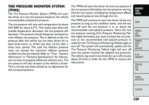
TIRE PRESSURE MONITOR SYSTEM
(TPMS)
The Tire Pressure Monitor System (TPMS) will warn
the driver of a low tire pressure based on the vehicle
recommended cold placard pressure.
The tire pressure will vary with temperature by about
0.07 BAR for every 6.5°C. This means that when the
outside temperature decreases, the tire pressure will
decrease. Tire pressure should always be set based on
cold inflation tire pressure. This is defined as the tire
pressure after the vehicle has not been driven for at
least three hours, or driven less than 1.6 km after a
three hour period. The cold tire inflation pressure
must not exceed the maximum inflation pressure
molded into the tire sidewall. Refer to “Tires – General
Information” in “Technical Specifications” for informa-
tion on how to properly inflate the vehicle’s tires. The
tire pressure will also increase as the vehicle is driven.
This is normal and there should be no adjustment for
this increased pressure.The TPMS will warn the driver of a low tire pressure if
the tire pressure falls below the low-pressure warning
limit for any reason, including low temperature effects
and natural pressure loss through the tire.
The TPMS will continue to warn the driver of low tire
pressure as long as the condition exists, and will not
turn off until the tire pressure is at or above the
recommended cold placard pressure. Once the low
tire pressure warning (Tire Pressure Monitoring Tell-
tale Light) illuminates, you must increase the tire pres-
sure to the recommended cold placard pressure in
order for the Tire Pressure Monitoring Telltale Light to
turn off. The system will automatically update and the
Tire Pressure Monitoring Telltale Light will turn off
once the system receives the updated tire pressures.
The vehicle may need to be driven for up to 20 minutes
above 25 km/h in order for the TPMS to receive this
information.
129
KNOWING
YOUR
VEHICLE
SAFETY
STARTING
AND
DRIVING
WARNING
LIGHTS
AND
MESSAGES
IN AN
EMERGENCY
SERVICING
AND
CARETECHNICAL
SPECIFICATIONSCONTENTS
Page 136 of 352

The TPMS has been optimized for the
original equipment tires and wheels.
TPMS pressures and warning have been
established for the tire size equipped on your
vehicle. Undesirable system operation or sensor
damage may result when using replacement
equipment that is not of the same size, type,
and/or style.Aftermarket wheels can cause sensor
damage. Do not use aftermarket tire sealants or
balance beads if your vehicle is equipped with a
TPMS, as damage to the sensors may result .
After inspecting or adjusting the tire pressure,
always reinstall the valve stem cap.This will pre-
vent moisture and dirt from entering the valve
stem, which could damage theTire Pressure Moni-
toring Sensor.
NOTE:
The TPMS is not intended to replace normal tire care and maintenance, or to provide warning of a tire
failure or condition.
The TPMS should not be used as a tire pressure gauge while adjusting your tire pressure.
Driving on a significantly under-inflated tire causes the tire to overheat and can lead to tire failure.
Under-inflation also reduces fuel efficiency and tire tread life, and may affect the vehicle’s handling and
stopping ability.
The TPMS is not a substitute for proper tire mainte- nance, and it is the driver’s responsibility to maintain
correct tire pressure using an accurate tire pressure
gauge, even if under-inflation has not reached the
level to trigger illumination of the Tire Pressure
Monitoring Telltale Light.
Seasonal temperature changes will affect tire pres- sure, and the TPMS will monitor the actual tire
pressure in the tire.
BASE SYSTEM
The Tire Pressure Monitor System (TPMS) uses wire-
less technology with wheel rim mounted electronic
sensors to monitor tire pressure levels. Sensors,
mounted to each wheel as part of the valve stem,
transmit tire pressure readings to the receiver module.
NOTE: It is particularly important for you to check
the tire pressure in all of the tires on your vehicle
monthly and to maintain the proper pressure.
The TPMS consists of the following components:
Receiver Module
Four Tire Pressure Monitoring Sensors
Tire Pressure Monitoring Telltale Light
130
KNOWING YOUR
VEHICLE
SAFETY
S
TARTING AND
DRIVING
WARNING LIGHTSAND
MESSAGES
IN AN
EMERGENCY
SERVICING AND
CARETECHNICAL
SPECIFICATIONSCONTENTS