Page 257 of 352

raise the spare tire into the storage area. Continue
to rotate the jack-handle assembly until you hear
the winch mechanism click three times. It cannot be
over tightened. Push against the tire several times to
be sure it is held securely in place.
JACKING INSTRUCTIONS
WARNING!
Carefully follow these tire changing
w
arnings to help prevent personal injury
or damage to your vehicle:
Always park on a firm, level surface as far from the
edge of the roadway as possible before raising the
vehicle.
Turn on the Hazard Warning flashers.
Block the wheel diagonally opposite the wheel
to be raised.
Set the parking brake firmly and set an auto-
matic transmission in PARK; a manual transmis-
sion in REVERSE.
Never start or run the engine with the vehicle
on a jack.
Do not let anyone sit in the vehicle when it is
on a jack.
(Continued)(Continued)
Do not get under the vehicle when it is on a
jack. If you need to get under a raised vehicle,
take it to a service center where it can be raised
on a lift .
Only use the jack in the positions indicated
and for lifting this vehicle during a tire change.
If working on or near a roadway, be extremely
careful of motor traffic .
To assure that spare tires, flat or inflated, are
securely stowed, spares must be stowed with the
valve stem facing the ground.
(fig. 153)
(fig. 153) Jack Warning Label
251
KNOWING
YOUR
VEHICLE
SAFETY
STARTING
AND
DRIVING
WARNING
LIGHTS
AND
MESSAGES
IN AN
EMERGENCY
SERVICING
AND
C ARETECHNICAL
SPECIFICATIONSCONTENTS
Page 258 of 352

Do not attempt to raise the vehicle by
jacking on locations other than those
indicated in the Jacking Instructions for
this vehicle.
(fig. 154)
1. Remove the spare tire, jack, and jack-handle from stowage.
2. Loosen, but do not remove, the wheel nuts on the wheel with the flat tire. Turn the wheel nuts coun-
terclockwise one turn while the wheel is still on the
ground.
3. Place the jack underneath the lift area that is closest to the flat tire. Center the jack saddle between the drain flute formations on the sill flange. Turn the
jack screw clockwise to firmly engage the jack saddle
with the lift area of the sill flange. (fig. 155)
(fig. 156)
4. Raise the vehicle by turning the jack screw clock- wise with the jack handle. Raise the vehicle until the
tire just clears the road surface and enough clear-
ance is obtained to install the spare tire. Minimum
tire lift provides maximum stability.
(fig. 154) Jacking Locations
(fig. 155)Front Jacking Location
252
KNOWING YOUR
VEHICLE
SAFETY
STARTING AND
DRIVING
WARNING LIGHTSAND
MESSAGES
IN AN
EMERGENC
Y
SERVICING AND
C
ARETECHNICAL
SPECIFICATIONSCONTENTS
Page 259 of 352
WARNING!
Raising the vehicle higher than neces-
s
ary can make the vehicle less stable. It
could slip off the jack and hurt someone near it .
Raise the vehicle only enough to remove the tire.5. Remove the wheel nuts. For vehicles so equipped,
remove the wheel cover from the wheel by hand.
Do not pry the wheel cover off. Then pull the wheel
off the hub.
WARNING!
To avoid possible personal injury, handle
t
he wheel covers with care to avoid con-
tact with any sharp edges.
6. Install the spare tire.Be sure to mount the spare tire with the
valve stem facing outward. The vehicle
could be damaged if the spare tire is
mounted incorrectly.
(fig. 157)
(fig. 156) Rear Jacking Location
(fig. 157) Mounting Spare Tire
253
KNOWING
YOUR
VEHICLE
SAFETY
STARTING
AND
DRIVING
WARNING
LIGHTS
AND
MESSAGES
IN AN
EMERGENCY
SERVICING
AND
C ARETECHNICAL
SPECIFICATIONSCONTENTS
Page 260 of 352

NOTE:
For vehicles so equipped, do not attempt to install acenter cap or wheel cover on the compact spare.
Refer to “Compact Spare Tire” and to “Limited-Use Spare” under “Tires — General Information” in
“Technical Specifications” for additional warnings,
cautions, and information about the spare tire, its
use, and operation.
7. Install the wheel nuts with the cone-shaped end of the nut toward the wheel. Lightly tighten the wheel
nuts.
WARNING!
To avoid the risk of forcing the vehicle
of
f the jack, do not tighten the wheel
nuts fully until the vehicle has been lowered.
Failure to follow this warning may result in per-
sonal injury.
8. Lower the vehicle by turning the jack screw coun- terclockwise with the jack handle.
9. Finish tightening the lug nuts. Push down on the wrench while at the end of the handle for increased
leverage. Tighten the lug nuts in a star pattern until
each nut has been tightened twice. The correct
tightness of each lug nut is 130 N·m. If in doubt
about the correct tightness, have them checked with a torque wrench by you authorized dealer or
service station.
10. Lower the jack to its fully closed position.
11. Place the deflated (flat) tire in the cargo area. Do
not stow the deflated tire in the spare tire
stowage location. Have the deflated (flat) tire
repaired or replaced as soon as possible.
12. To stow the winch cable and retainer, fit the assembled jack-handle over the winch drive nut.
Rotate the jack-handle assembly clockwise until
you hear the winch mechanism click three times. It
cannot be over tightened.
13. Stow the jack-handle and jack. Remove the wheel blocks from the vehicle and release the park brake.
14. Check the tire pressure as soon as possible. Adjust the tire pressure as required.
ROAD TIRE INSTALLATION
Vehicles Equipped With Wheel Covers
1. Mount the road tire on the axle.
2.
To ease the installation process for steel wheels with
wheel covers, install two lug nuts on the mounting
studs which are on each side of the valve stem. Install
the lug nuts with the cone shaped end of the nut
toward the wheel. Lightly tighten the lug nuts.
254
KNOWING YOUR
VEHICLE
SAFETY
STARTING AND
DRIVING
WARNING LIGHTSAND
MESSAGES
IN AN
EMERGENC
Y
SERVICING AND
C
ARETECHNICAL
SPECIFICATIONSCONTENTS
Page 261 of 352

WARNING!
To avoid the risk of forcing the vehicle
of
f the jack, do not tighten the wheel
nuts fully until the vehicle has been lowered.
Failure to follow this warning may result in per-
sonal injury.
(fig. 158)
3. Align the valve notch in the wheel cover with the valve stem on the wheel. Install the cover by hand, snapping the cover over the two lug nuts. Do not
use a hammer or excessive force to install the cover.
4. Install the remaining lug nuts with the cone shaped end of the nut toward the wheel. Lightly tighten the
lug nuts.
WARNING!
To avoid the risk of forcing the vehicle
of
f the jack, do not tighten the wheel
nuts fully until the vehicle has been lowered.
Failure to follow this warning may result in per-
sonal injury.
5. Lower the vehicle to the ground by turning the jack handle counterclockwise.
6. Finish tightening the lug nuts. Push down on the wrench while at the end of the handle for increased
leverage. Tighten the lug nuts in a star pattern until
each nut has been tightened twice. The correct
tightness of each lug nut is 130 N·m. If in doubt
about the correct tightness, have them checked
with a torque wrench by your authorized dealer or
service station.
7. After 40 km check the lug nut torque with a torque wrench to ensure that all lug nuts are properly
seated against the wheel.
(fig. 158) Tire And Wheel Cover Or Center Cap1 — Valve Stem 4 — Wheel Cover
2 — Valve Notch 5 — Mounting Stud
3 — Wheel Lug Nut
255
KNOWING
YOUR
VEHICLE
SAFETY
STARTING
AND
DRIVING
WARNING
LIGHTS
AND
MESSAGES
IN AN
EMERGENCY
SERVICING
AND
C ARETECHNICAL
SPECIFICATIONSCONTENTS
Page 262 of 352

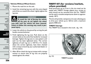
Vehicles Without Wheel Covers
1. Mount the road tire on the axle.
2. Install the remaining lug nuts with the cone shapedend of the nut toward the wheel. Lightly tighten the
lug nuts.
WARNING!
To avoid the risk of forcing the vehicle
of
f the jack, do not tighten the wheel
nuts fully until the vehicle has been lowered.
Failure to follow this warning may result in per-
sonal injury.
3. Lower the vehicle to the ground by turning the jack handle counterclockwise.
4. Finish tightening the lug nuts. Push down on the wrench while at the end of the handle for increased
leverage. Tighten the lug nuts in a star pattern until
each nut has been tightened twice. The correct
tightness of each lug nut is 130 N·m. If in doubt
about the correct tightness, have them checked
with a torque wrench by your authorized dealer or
service station.
5. After 40 km check the lug nut torque with a torque wrench to ensure that all lug nuts are properly
seated against the wheel. TIREFIT KIT (for versions/markets,
where provided)
Small punctures up to 6 mm in the tire tread can be
sealed with TIREFIT. Foreign objects (e.g., screws or
nails) should not be removed from the tire. TIREFIT
can be used in outside temperatures down to approxi-
mately 20°C.
This kit will provide a temporary tire seal, allowing you
to drive your vehicle up to 160 km with a maximum
speed of 88 km/h.
TIREFIT Storage
The TIREFIT kit is located in the trunk.
(fig. 159)
(fig. 159)
TIREFIT Location
256
KNOWING YOUR
VEHICLE
SAFETY
STARTING AND
DRIVING
WARNING LIGHTSAND
MESSAGES
IN AN
EMERGENC
Y
SERVICING AND
C
ARETECHNICAL
SPECIFICATIONSCONTENTS
Page 263 of 352

TIREFIT KIT COMPONENTS AND
OPERATION(fig. 160)
1. Sealant Bottle
2. Deflation Button
3. Pressure Gauge
4. Power Button
5. Mode Select Knob
6. Sealant Hose (Clear)
7. Air Pump Hose (Black)
8. Power Plug Using The Mode Select Knob And Hoses
Your TIREFIT kit is equipped with the following sym-
bols to indicate the air or sealant mode.
Selecting Air Mode
Turn the Mode Select Knob (5) to this posi-
tion for air pump operation only. Use the
Black Air Pump Hose (7) when selecting this
mode.
Selecting Sealant Mode Turn the Mode Select Knob (5) to
this position to inject the TIREFIT
Sealant and to inflate the tire. Use
the Sealant Hose (clear hose) (6)
when selecting this mode.
Using The Power Button Push and release the Power Button (4) once
to turn On the TIREFIT kit. Push and release
the Power Button (4) again to turn Off the
TIREFIT kit.
Using The Deflation Button Press the Deflation Button (2) to reduce the
air pressure in the tire if it becomes over-
inflated.(fig. 160)
257KNOWING
YOUR
VEHICLE
SAFETY
STARTING
AND
DRIVING
WARNING
LIGHTS
AND
MESSAGES
IN AN
EMERGENC Y
SERVICING
AND
C ARETECHNICAL
SPECIFICATIONSCONTENTS
Page 264 of 352

TIREFIT Usage Precautions
Replace the TIREFIT Sealant Bottle (1) and SealantHose (6) prior to the expiration date (printed on the
bottle label) to assure optimum operation of the
system. Refer to “Sealing a Tire with TIREFIT” sec-
tion (F) “Sealant Bottle and Hose Replacement”.
The Sealant Bottle (1) and Sealant Hose (6) are a one tire application use. After each use, always replace
these components immediately at an authorized
dealer.
When the TIREFIT sealant is in a liquid form, clean water, and a damp cloth will remove the material
from the vehicle or tire and wheel components.
Once the sealant dries, it can easily be peeled off and
properly discarded.
For optimum performance, make sure the valve stem on the wheel is free of debris before connecting the
TIREFIT kit.
You can use the TIREFIT air pump to inflate bicycle tires. The kit also comes with two needles, located in
the Accessory Storage Compartment (on the bot-
tom of the air pump) for inflating sport balls, rafts, or
similar inflatable items. However, use only the Air
Pump Hose (7) and make sure the Mode Select Knob
(5) is in the Air Mode when inflating such items to
avoid injecting sealant into them. The TIREFIT Seal- ant is only intended to seal punctures less than 6 mm
diameter in the tread of your vehicle.
Do not lift or carry the TIREFIT kit by the hoses.
WARNING!
Do
not attempt to seal a tire on the
side of the vehicle close to traffic . Pull
far enough off the road to avoid the danger of
being hit when using the TIREFIT kit .
Do not use TIREFIT or drive the vehicle under
the following circumstances:
– If the puncture in the tire tread is approxi-
mately 6 mm or larger.
– If the tire has any sidewall damage.
– If the tire has any damage from driving with
extremely low tire pressure.
– If the tire has any damage from driving on a
flat tire.
– If the wheel has any damage.
– If you are unsure of the condition of the tire or
the wheel.
Keep TIREFIT away from open flame or heat
source.
(Continued)
258
KNOWING YOUR
VEHICLE
SAFETY
STARTING AND
DRIVING
WARNING LIGHTSAND
MESSAGES
IN AN
EMERGENC
Y
SERVICING AND
C
ARETECHNICAL
SPECIFICATIONSCONTENTS