Page 121 of 318
![AUDI A8 2013 Owners Manual A WARNING 1=
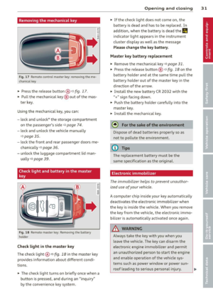
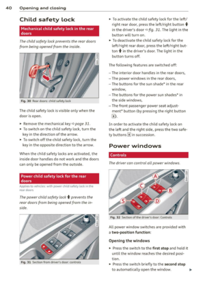
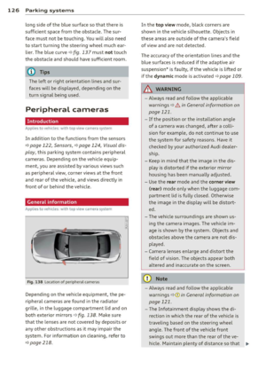
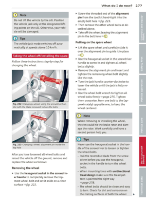
Please note that the wheels could spin on
slick or slippery roads when kick-down is
act ive.
Transmission malfunction
[O] Transmission: please pre ss the brake ped
a AUDI A8 2013 Owners Manual A WARNING 1=
Please note that the wheels could spin on
slick or slippery roads when kick-down is
act ive.
Transmission malfunction
[O] Transmission: please pre ss the brake ped
a](/manual-img/6/57614/w960_57614-120.png)
A WARNING 1=
Please note that the wheels could spin on
slick or slippery roads when kick-down is
act ive.
Transmission malfunction
[O] Transmission: please pre ss the brake ped
al and select the position again
Press the brake pedal and select the des ired
selector lever pos it ion again. You can then
continue dr iv ing .
[O] Transmission hot: please modify driving
style
The transmission temperature has increased
significantly due to the sporty driving manner. Drive in a less sporty manner until the tem
perature returns to the normal range and the
in dicator light switches of .
[O] Gearbox malfunction: you can continue
driving
There is a system ma lfunction in the transmis
sion. You may continue driving. Drive to your
authorized Audi dealer or qualified repair fa
cility soon to have the malfunction corrected.
l'§J/1;1 Gearbox malfunction: you can contin
ue driving in D only until engine is off
There is a system malfunction in the transmis
sion. The transmission is switching to emer
gency mode. If you turn the engine off, you
will not be able to select any other selector
lever positions after start ing the engine again.
Drive to your authorized Aud i dealer or quali
fied repair facility immediately to have the
malfunction corrected.
[O] Gearbox malfunction: you can continue
driving (limited functionality)
There is a system ma lfunction in the transmis
sion. The transmission is switching to emer
gency mode. This mode only shifts into cer
tain gears or will not longer shift at all. The
engine may stall. Dr ive to your authorized
Aud i dealer or qualified repair facility immedi
ately to have the malfunction corrected.
Automatic Transmission 119
[o];ffl Gearbox malfunction: no reverse gear
(you can continue driving)
The re is a system malfunction in the transmis
s ion. The transmission is switching to emer
gency mode. This mode on ly shifts into cer
tain gears or will not longer shift at a ll. You
cannot engage the reverse gear . Dr ive to your
authorized Aud i dea ler immediately to have
the malfunction corrected.
[O] Vehicle may roll! Cannot shift to P. Please
apply parking brake
-The parking lock was released using the
emergency release ¢
page 120. Or
- The parking brake cannot engage automati
cally . Drive to your authorized Audi dea ler o r
qualified repair facility immediately to have
the malfunction corrected.
[O] Gearbox malfunction: Stop and shift to P
Do not continue dr iving . Select the P selector
lever position and see your authorized Audi
dealer or qualified repair facility for assis
tance.
Page 122 of 318

120 Automatic Transmission
Parking lock emergency release
The parking lock must be released using the
emergency release before towing the vehicle .
@
Fig. 126 Dr iver's side footwell: releasing t he park ing
lock us ing t he emergency release
Fig. 127 Drive r's s ide footwe ll: resetting th e pa rking
l ock
The emergency release is located under the
floor mat on the driver's side. You operate the
emergency re lease from the dr iver's seat.
Releasing the parking lock using the
emergency release
• To prevent the vehicle from rolling uninten
tionally, set the park ing brake© ¢
page 85
or press the brake peda l.
.. There are two slits on the cover. Position
the screwdriver from the vehicle tool kit in
one of the s lits on the cover and pry the cov
er off.
• Pull the band@ in the direction of the ar
row until the release lever locks in place
¢ fig . 126.
• Fold the uppe r section of the release lever
down into the recess.
Resetting the parking lock
• Press the button @ and the release lever at
the same time . You can now push the lever back into its original pos
ition . Make sure the
lever locks in place
¢fig. 127.
.. Install the cover .
T he indicator light
[O] and the N position indi
cator in the instrument cluster turn on when
the parking lock is released using the emer
gency release . The message
Risk of rolling! P
not possible . Please set the park ing brake
a l
so appears.
A WARNING
If you release the park ing lock using the
emergency release, secure your vehicle
with the pa rking brake or the brake pedal
i f the parking brake is not working. The ve
hicle can roll away if it is not secured and
cause a crash.
Page 123 of 318

Parking systems
General information
App lies to vehicles: with park in g system plus/rear view
camera/peripheral cameras
Depending on your vehicle's equipment, vari
ous parking aids will help you when parking
and maneuvering.
The
advanced parking system with rear view
camera
ass ists you when parking by audibly
and v isua lly indicating objects detected
in
front of
and behind the vehicle . The rear view
camera shows the area behind the vehicle in
the Infotainment display. This display assists
you when you are cross or para llel parking
c:;,page 122.
The peripheral cameras assist you with park
ing and maneuvering. You are aided by various
cameras depending on the vehicle equipment level ¢
page 126. In addition, you are assist
ed by the functions from the sensors
c:;, page 122, Sensors, c:;, page 124 , Visual
display .
A WARNING
-Always look fo r traff ic and check the area
around your vehicle by looking at it di
rect ly as well. The parking system cannot
replace the driver's attention. The driver
is a lways respons ible for safety during
parking and for all other maneuvers.
- Please note that some sur faces, such as
clothing, are not detected by the system .
- Sensors and cameras have blind spots in
which peop le and objects cannot be de
tected. Be especially cautious of children
and animals.
- The sensors can be displaced by impacts
or damage to the radiator grille, bumper,
wheel housing and the underbody. The
parking systems may become impaired
as a result. Have your authorized Audi
dealer or qualified workshop check their
function.
- Make sure the sensors are not covered by
stickers, deposits or any other obstruc
t ions as it may impair the sensor func-
Parking systems 121
tion. For information on cleaning, refer
to
c:;, page 218.
(D Note
-Some objects are not detected by the
system under certain circumstances:
- Objects such as barr ier chains, trailer
draw bars, vertical poles or fences
- Objects above the sensors such as wall
extensions
- Objects w ith specific surfaces or struc
tures such as chain link fences or pow
der snow .
- If you continue driving closer to a low-ly
ing object, it may disappear from the
sensor range. Note that you w ill no lon
ger be warned about this obstacle .
(D Tips
- The system may provide a warning even
though there are no obstacles in the cov
erage area in some situations, such as:
- certain road surfaces or for long grass.
- externa l ult rason ic so urces e.g. from
cleaning vehicles.
- heavy rain, snow or thick vehicle ex
haust.
- We recommend that you practice park
ing in a traffic-free location or parking
lot to become familiar w ith the system.
When doing this, there should be good
light and weather cond itions.
- You can change the volume and pitch of
the signals as we ll as the disp lay
c:;, page 131.
-Please refer to the instructions for tow
ing a trailer
c:;, page 131.
- What appears in the infotainment dis
play is somewhat time-delayed.
Page 124 of 318

122 Parking systems
Advanced parking
system with rear view
camera
Introduction
Applies to vehicles: with advanced park ing system with
rear view camera
Fig. 128 Illust rat ion: Cross parking
Fig. 129 Illust ration: paralle l parking
g
:i:
"' "'
Vehicles with the park ing system advanced
are equipped with a rear view camera in addi
tion to the acoustic and v isua l park ing system.
You can use
cross parking for example, to
park in a parking space or in a garage
c:> fig. 128. You can use parallel parking if you
would like to park on the side of the road
¢ fig. 129 .
General information
Applies to vehicles: with advanced parking system with
rear view camera
Fig. 130 Area covered (D and area not covered@by
the rear v iew camera
AU Dl
Fig. 131 Rear lid: Location of t he rear view camera
Sensors
Sensors are located in the front and rear
bumpers . If these detect an obstacle, visual
and in some situations audible signa ls warn
you .
Make sure the sensors are not covered by
stickers, deposits or any other obstructions as
it may impair the sensor function. For infor
mation on cleaning, refer to
c:> page 218 .
The disp lay field begins approximately at:
front side
3 ft (0.90 m)
center
4 ft (1.20 m)
side 2
ft (0.60 m)
rear center
T he closer you get to the obstacle, the shorter
the interval between the audible signals . A
continuous tone sounds w hen the obstacle is
less than approximately 1
ft (0.30 m) away.
Do not continue driving farther
c::> .&. in Gener
al information on page 121, c:>(Din General
information on page 121
!
Page 125 of 318

If the distance to an obstacle remains con
stant, the volume of the distance warning
gradually drops after about four seconds (this
does not apply in the continuous tone range).
Rear view camera
The rear view camera is locat ed above the rear
license plate bracket. Make sure that the lens
for the parking system
r::;, fig. 131 is not cov
ered by deposits or any other obstructions be
cause this can affect the function of the park
ing system. For information on clean ing, refer
to
c;, page 218.
The rear view camera coverage area includes
(Dr::;, fig. 130. Only this area is shown in the
Infotainment display. Objects that are outside
of this area @are not displayed.
The accuracy of the orientation lines and the
blue surfaces is reduced if the adaptive air
suspens ion* is faulty, if the veh icle is lifted or
if the
dynamic mode is activated r::;, page 109.
A WARNING
-Always read and follow the applicable
warnings
r::;, &. in General information on
page 121.
- If the position and the installation angle
of the rear view camera was changed, for
example, after a collision, do not contin
ue to use the system for safety reasons.
Have it checked by your authorized Audi
dealership or authorized repair facility.
- Only use the rear view camera to assist
you if it shows a good, clear picture. For
example, the image may be affected by
the sun shining into the lens, dirt on the
lens or if there is a system fault.
- Use the rear view camera only if the lug
gage compartment lid is comp letely
closed. Make sure any objects you may
have mounted on the luggage compart
ment lid do not block the rear view cam
era .
- The camera lens enlarges and distorts the field of vision. The object appears both altered and inaccurate on the
screen.
Parking systems 123
-In certain situations, people or objects in
the display appear closer or further
away:
- objects that do not touch the ground,
such as the bumper of a parked vehicle,
a trailer hitch or the rear of a truck. Do
not use the help lines in this case.
- If driven from a level surface onto an
inclin e, or a downward slope.
-If driven toward protruding objects.
- If the vehicle is carrying too much load
in the rear.
(D Note
-Always read and follow the applicable
warnings
r::;, (D in General information on
page 121.
- The orange colored orientation lines in
the Infotainment display show the vehi cle path depending on the steering
wheel angle. The front of the vehicle
front swings out more than the rear of
the vehicle. Maintain plenty of distance
so that your outside mirror or a corner of
your vehicle does not collide with any ob stacles.
Page 126 of 318

124 Park in g sy ste m s
Switching on /off
Appl ies to vehicles: with advanced parking system wit h
rear view camera
Fig. 132 Center console: Park ing system switch
Fig. 133 Infota inment: visual distance d isplay
Switching on
.. Shift into reverse or
.. press the
P,#A button in the center console
¢ fig. 132. A short confirmat ion tone
sounds a nd the L ED in the button t urns on.
Sw itching between the rear view camer a
and optical displa y
.. Press the Graphic control button ®
¢ page 124, fig. 134 to see the opt ical dis
play .
.. Press the
Rearv ie w control button to see
the rear view camera image .
Switching off
.. Drive forwa rd faster than 6 mph (10 km/h),
o r
.. Press the
P'#A b utton, o r
.. Switch the ignition off.
Visual displa y
Using the segments, you can estimate the dis
tance to an object in front of or behind the ve
h icle
¢fig .133. T he red lines mark the ex-pected direction of t
ravel according to the
steering ang le . A white segment indicates an
identified obstacle that is outside of the vehi
cle's path. Red segments show identified ob
stacles that are in your vehicle's path. As your
vehicle comes closer to the obstacle, the seg
ments move closer to the vehicle. At the lat
est the collision area has been reached when
the next to last segment is displayed . Obsta
cles in the collision area , includ ing those out
s ide of the vehicle's path, are shown in red. Do
not cont inue driving farther forward or in re
verse
¢ .&. in General information on
page 121,
¢ 0 in General information on
page 121.
(D Tips
The visual display in the left part of the
display should help you detect the critical
vehicle areas.
Cross parking
Applies to vehicles: with advanced parking system with
rear view ca mera
This view may be used when parking in a ga
rage or in a parking space .
Fig . 1 34 Infota inment: aimi ng a t a parking space
Fig. 135 Infotainment: aligning th e ve hicle
Page 127 of 318

.. Turn the In fotainme nt on and shift into re
verse gear .
.. The orange colored orientation lines@
show the direction of travel of the vehicle.
Turn the steer ing wheel until the orange ori
entat io n lines appear in the parking space
¢
fig. 134 . Use the markings @to help you
est imate the distance from an obstacle .
E ach ma rking represen ts about 3 ft ( 1 m).
The blue area rep resents an extens ion of the
vehicle's out line by approximately 16 ft
(S m) to the rear .
.. While driving in reverse gear, adjust the
steering wheel angle to fit the park ing space
with the aid of the orange orientation lines
¢ & in General information on page 123,
c:>(D in General information on page 123.
@ marks t he rear bumper. Stop the veh icle
when the red orientation line@ borders an
object.
Parallel parking
Appl ies to vehicles : with advanced parking system with
rear vi ew camera
This view may be used when parallel parking
along the side of a street.
Fig . 136 Infotainment: blue s urface aligned in the
parking space
F ig . 137 Infotainment: contact of t he blue curved line
with the curb
P arking sys tems 125
Parking on the right is descr ibed here. It is
identical when parking on the left.
If there is an obstacle next to the parking
space (su ch as a wall), re fer to info rmat io n for
" P ark ing next to obstacles"
¢ page 125.
.. Ac tivate the t urn signa l.
.,. Pos it io n your veh icle next to a par ked vehi
cle in fro nt of the des ired parking space. The
distance to this vehicle should be approxi
mate ly 3 ft (1 m) .
.. Turn the Infotainment on and shift into re
verse gear . The parking system is turned on
and the
cross parking indicator is displayed.
.. Press the control button o n the Infotain
ment un it CD ¢
fig. 136. The parallel park
ing
ind icator is displayed.
.. Bac k up and alig n your vehicle so the blue
a rea @ borders on the rear end of the veh i
cle behind you or on the parking space line
¢ & in General information on page 123,
¢ (D in General information on page 123.
The blue area represents an extension of the
veh icle's outline by approximately 16 ft
(S m) to the rear. The long side of the blue
area should be on the c urb . The entire b lue
area must fit into the parking space .
.,. With the vehicle stopped, t urn the stee ring
wheel to the r ight as fa r as it will go .
.. Ba ck into the p arking space until t he bl ue
curve ¢
fig. 137 to uches the cu rb ¢ & in
General information on page 123,
c:>(D in
General information on page 123 .
Stop the
veh icle .
.. With the vehicle stopped, turn the steering
wheel to the left as far as it will go .
.,. Continue to back into t he parking space un
til the veh icle is pa rked parallel to the curb
c::> .&, in Gen eral information on page 123,
c::> (D in General informa tion on page 123.
@ marks the rear bumper. Stop the vehicle,
a t the la tes t, when the red orien tat ion line
@ borders an object . Keep an eye on the
front of your vehicle while doing this.
Parking next to obstacles
If there is an obstacle (su ch as a wa ll) next to
t he pa rking space, pos ition the vehicle so
there is mo re space on that side. Pos ition the
II--
Page 128 of 318

126 Parking systems
long side of the blue surface so that there is
sufficient space from the obstacle. The sur
face m ust not be to uchi ng. You will a lso need
to start tur ning the steer ing wheel much ear
lier. The blue curve
r:::;, fig. 13 7 must not touch
the obstacle and should have sufficient room .
@ Tips
The left or right orientation lines and sur
faces will be displayed, depending on the turn signa l be ing used .
Peripheral cameras
Introduction
Applies to vehicles: with top view camera system
In addition to the f unctions from the sensors
c::> page 122, Sensors, c::> page 124, Visual dis
play,
this parking system contains peripheral
cameras. Depending on the ve hicle equ ip
ment, you are assisted by various
views such
as periphera l view, corner views at the front
and rear of the veh icle, and views di rectly in
fro nt of o r behind the vehicle.
General information
Applies to vehicles: with top view camera system
Fig. 138 Locat io n of peripheral cameras
Depending on the vehicle equ ipment, the pe
ripheral cameras are found in the radiator
grille, i n the luggage compartment lid and on
both exterior mirrors
r:::;, fig . 138 . Make sure
that the lenses are not covered by deposits or
any other obstructions as it may impair the
system. For information on cleani ng, refer to
c::> page 218.
In the to p view mode, b lack corners are
shown in t he vehicle silhouette . Objects in
these areas are outside of the camera 's field
of
view and are not detected .
T he accuracy of the o rientation lines and the
blue surfaces is reduced if the adaptive air
suspension * is faulty, if the vehicle is lifted or
if the
dy namic mode is activated r:::;, page 109.
A WARNING
-- Always read and follow the applicable
warn ings
r:::;, & in General information on
page 121 .
-If the position or the installat io n angle
of a camera was changed, after a colli
sion for example, do not continue to use
the system fo r safety reasons. Have it
checked by your author ized Audi deale r
sh ip.
- Keep in mind that the image in the dis
p la y is distorted if the exterior mi rror
housing has bee n manually adjusted .
- U se the
rear mode and the corn er view
( rear)
m od e only when the luggage com
partment lid is fu lly closed . Otherw ise
the image in the display will be d istort
ed .
- The vehicle surro undings are shown us
ing the came ra images. The vehicle im
age is shown by the system. Ob jects and
obstacles above the camera are not d is
p layed.
- Camera lenses enlarge and distort the field of vision. The objects appear both
altered and inaccurate on the screen.
(D Note
- Always read and follow the applica ble
warnings
¢ (I) in General information on
page 121.
- The Infotainment d isplay shows the di
rection in which the rear of the vehicle is
traveling based on the steer ing whee l
ang le. The front of the vehicle front
sw ings out mo re than the rear of the
ve
hicl e. M aintain pl enty of d istance so that .,_