Page 33 of 112

INSTRUMENT AND CONTROL FUNCTIONS
3-18
3
EAU13221
Fuel Make sure there is sufficient gasoline in
the tank.
WARNING
EWA10881
Gasoline and gasoline vapors are
extremely flammable. To avoid fires
and explosions and to reduce the
risk of injury when refueling, follow
these instructions.1. Before refueling, turn off the en-gine and be sure that no one is sit-
ting on the vehicle. Never refuel
while smoking, or while in the vi-
cinity of sparks, open flames, or
other sources of ignition such as
the pilot lights of water heaters and
clothes dryers.
2. Do not overfill the fuel tank. When refueling, be sure to insert the
pump nozzle into the fuel tank filler
hole. Stop filling when the fuel
reaches the bottom of the filler
tube. Because fuel expands when
it heats up, heat from the engine or
the sun can cause fuel to spill out
of the fuel tank. 3. Wipe up any spilled fuel immedi-
ately. NOTICE: Immediately wipe
off spilled fuel with a clean, dry,
soft cloth, since fuel may deteri-
orate painted surfaces or plastic
parts.
[ECA10071]
4. Be sure to securely close the fuel tank cap.
WARNING
EWA15151
Gasoline is poisonous and can
cause injury or death. Handle gaso-
line with care. Never siphon gaso-
line by mouth. If you should swallow
some gasoline or inhale a lot of gas-
oline vapor, or get some gasoline in
your eyes, see your doctor immedi- ately. If gasoline spills on your skin,
wash with soap and water. If gaso-
line spills on your clothing, change
your clothes.
EAU13391
NOTICE
ECA11400
Use only unleaded gasoline. The use
of leaded gasoline will cause severe
damage to internal engine parts,
such as the valves and piston rings,
as well as to the exhaust system.Your Yamaha engine has been de-
signed to use premium unleaded gaso-
line with a research octane number of
95 or higher. If knocking (or pinging) oc-
curs, use a gasoline of a different
1. Fuel tank filler tube
2. Maximum fuel level
2
1
Recommended fuel:
Premium unleaded gasoline only
Fuel tank capacity: 17.3 L (4.57 US gal, 3.81 Imp.gal)
Fuel reserve amount (when the fuel
level warning light comes on): 3.5 L (0.92 US gal, 0.77 Imp.gal)
U1JSE0E0.book Page 18 Wednesday, July 27, 2011 10:34 AM
Page 34 of 112

INSTRUMENT AND CONTROL FUNCTIONS
3-19
3brand. Use of unleaded fuel will extend
spark plug life and reduce maintenance
costs.
EAU51150
Fuel tank breather hose and
overflow hose Before operating the motorcycle:●
Check each hose connection.
●
Check each hose for cracks or
damage, and replace if damaged.
●
Make sure that the end of each
hose is not blocked, and clean if
necessary.
●
Make sure that the end of each
hose is positioned outside of the
cowling.
EAU13445
Catalytic converters This vehicle is equipped with catalytic
converters in the exhaust system.
WARNING
EWA10862
The exhaust system is hot after op-
eration. To prevent a fire hazard or
burns:●
Do not park the vehicle near
possible fire hazards such as
grass or other materials that
easily burn.
●
Park the vehicle in a place
where pedestrians or children
are not likely to touch the hot
exhaust system.
●
Make sure that the exhaust sys-
tem has cooled down before do-
ing any maintenance work.
●
Do not allow the engine to idle
more than a few minutes. Long
idling can cause a build-up of
heat.
1. Fuel tank breather hose and overflow hose
U1JSE0E0.book Page 19 Wednesday, July 27, 2011 10:34 AM
Page 35 of 112
INSTRUMENT AND CONTROL FUNCTIONS
3-20
3
NOTICE
ECA10701
Use only unleaded gasoline. The use
of leaded gasoline will cause unre-
pairable damage to the catalytic
converter.
EAU39033
Seats Rider seat
To remove the rider seatPull back the rear of the rider seat as
shown, remove the bolts, and then pull
the seat off.
To install the rider seatInsert the projection on the front of the
rider seat into the seat holder as
shown, place the seat in the original po-
sition, and then install the bolts.Passenger seat
To remove the passenger seat
1. Insert the key into the seat lock,
and then turn it clockwise.
1. Bolt
1. Projection
2. Seat holder
1. Seat lock
2. Unlock.
U1JSE0E0.book Page 20 Wednesday, July 27, 2011 10:34 AM
Page 36 of 112

INSTRUMENT AND CONTROL FUNCTIONS
3-21
32. While holding the key in that posi-
tion, lift the front of the passenger
seat and pull it forward.
To install the passenger seat
1. Insert the projections on the pas- senger seat into the seat holders
as shown, and then push the front
of the seat down to lock it in place.
2. Remove the key.TIPMake sure that the seats are properly
secured before riding.
EAU39073
Helmet holding cable A helmet holding cable is provided in
the owner’s tool kit to secure two hel-
mets to the helmet cable holder
equipped on the bottom of the passen-
ger seat.
To secure a helmet with the helmet
holding cable 1. Remove the passenger seat. (See page 3-20.)
2. Clip the middle snap hook of the cable onto the cable holder. 3. Pass one of the other snap hooks
of the cable through the helmet
strap buckle, and then clip the
snap hook onto the cable holder as
shown.
4. Install the passenger seat. WARNING! Never ride with a
helmet attached to a helmet
holding cable, since the helmet
may hit objects, causing loss of
control and possibly an acci-
dent.
[EWA14331]
1. Projection
2. Seat holder
1. Helmet holding cable
2. Helmet cable holder
3. Middle snap hook
1. Snap hook
2. Helmet holding cable
3. Helmet
1
2
3
U1JSE0E0.book Page 21 Wednesday, July 27, 2011 10:34 AM
Page 37 of 112

INSTRUMENT AND CONTROL FUNCTIONS
3-22
3
To release a helmet from the helmet
holding cable 1. Remove the passenger seat.
2. Unfasten the snap hooks from the cable holder, and then remove the
cable from the helmet strap buck-
le.
3. Install the passenger seat.
EAU39671
Rear view mirrors The rear view mirrors of this vehicle can
be folded forward or backward for park-
ing in narrow spaces. Fold the mirrors
back to their original position before
riding.
WARNING
EWA14371
Be sure to fold the rear view mirrors
back to their original position before
riding.
EAU38945
Adjusting the front fork
WARNING
EWA10180
Always adjust both fork legs equal-
ly, otherwise poor handling and loss
of stability may result.This front fork is equipped with spring
preload adjusting bolts, rebound damp-
ing force adjusting screws, compres-
sion damping force adjusting bolts (for
fast compression damping) and com-
pression damping force adjusting bolts
(for slow compression damping).NOTICE
ECA10101
To avoid damaging the mechanism,
do not attempt to turn beyond the
maximum or minimum settings.Spring preload
To increase the spring preload and
thereby harden the suspension, turn
the adjusting bolt on each fork leg in di-
rection (a). To decrease the spring pre-
load and thereby soften the
suspension, turn the adjusting bolt on
each fork leg in direction (b).
1. Helmet holding cable
2. Helmet
1. Riding position
2. Parking position
2
2
1
2
2
1
U1JSE0E0.book Page 22 Wednesday, July 27, 2011 10:34 AM
Page 38 of 112

INSTRUMENT AND CONTROL FUNCTIONS
3-23
3Align the appropriate groove on the ad-
justing mechanism with the top of the
front fork collar. Rebound damping force
To increase the rebound damping force
and thereby harden the rebound damp-
ing, turn the adjusting screw on each
fork leg in direction (a). To decrease the
rebound damping force and thereby
soften the rebound damping, turn the
adjusting screw on each fork leg in di-
rection (b).Compression damping force
To adjust the compression damping
force (for fast compression damping)To increase the compression damping
force and thereby harden the compres-
sion damping, turn the adjusting bolt on
each fork leg in direction (a). To de-
crease the compression damping force
and thereby soften the compression
damping, turn the adjusting bolt on
each fork leg in direction (b).
1. Spring preload adjusting bolt
1. Current setting
2. Front fork collar
1
1
(a)
(b)
Spring preload setting:
Minimum (soft):
0
Standard:
2
Maximum (hard): 51. Rebound damping force adjusting screw
1
1
(a) (b)
Rebound damping setting:
Minimum (soft):
25 click(s) in direction (b)*
Standard:
20 click(s) in direction (b)*
Maximum (hard): 1 click(s) in direction (b)*
* With the adjusting screw fully turned in direction (a)
U1JSE0E0.book Page 23 Wednesday, July 27, 2011 10:34 AM
Page 39 of 112
To increase the compression damping
force and thereby harden the compres-
sion damping, tu")
INSTRUMENT AND CONTROL FUNCTIONS
3-24
3
To adjust the compression damping
force (for slow compression damping)To increase the compression damping
force and thereby harden the compres-
sion damping, turn the adjusting bolt on
each fork leg in direction (a). To de-
crease the compression damping force and thereby soften the compression
damping, turn the adjusting bolt on
each fork leg in direction (b).
TIPAlthough the total number of clicks or
turns of a damping force adjusting
mechanism may not exactly match the above specifications due to small differ-
ences in production, the actual number
of clicks or turns always represents the
entire adjusting range. To obtain a pre-
cise adjustment, it would be advisable
to check the number of clicks or turns of
each damping force adjusting mecha-
nism and to modify the specifications
as necessary.
1. Compression damping force adjusting bolt
(for fast compression damping)Compression damping setting (for
fast compression damping):Minimum (soft):
4 turn(s) in direction (b)*
Standard: 2 turn(s) in direction (b)*
Maximum (hard): 0 turn(s) in direction (b)*
* With the adjusting bolt fully turned in
direction (a)
1
1
(a)
(b)
1. Compression damping force adjusting bolt (for slow compression damping)
Compression damping setting (for
slow compression damping):Minimum (soft):
20 click(s) in direction (b)*
Standard: 15 click(s) in direction (b)*
Maximum (hard): 1 click(s) in direction (b)*
* With the adjusting bolt fully turned in
direction (a)
1
1
(a)
(b)
U1JSE0E0.book Page 24 Wednesday, July 27, 2011 10:34 AM
Page 40 of 112

INSTRUMENT AND CONTROL FUNCTIONS
3-25
3
EAU42946
Adjusting the shock absorber
assembly This shock absorber assembly is
equipped with a spring preload adjust-
ing ring, a rebound damping force ad-
justing screw, a compression damping
force adjusting bolt (for fast compres-
sion damping) and a compression
damping force adjusting bolt (for slow
compression damping).NOTICE
ECA10101
To avoid damaging the mechanism,
do not attempt to turn beyond the
maximum or minimum settings.Spring preload
To increase the spring preload and
thereby harden the suspension, turn
the adjusting ring in direction (a). To de-
crease the spring preload and thereby
soften the suspension, turn the adjust-
ing ring in direction (b).●
Align the appropriate notch in the
adjusting ring with the position in-
dicator on the shock absorber.
●
Use the special wrench and the
extension bar included in the own-
er’s tool kit to make the adjust-
ment.Rebound damping force
To increase the rebound damping force
and thereby harden the rebound damp-
ing, turn the adjusting screw in direction
(a). To decrease the rebound damping
force and thereby soften the rebound
damping, turn the adjusting screw in di-
rection (b).
1. Spring preload adjusting ring
2. Position indicator
3. Extension bar
4. Special wrenchSpring preload setting:
Minimum (soft):1
Standard: 4
Maximum (hard):
9
1
4
32
1. Rebound damping force adjusting screwRebound damping setting:Minimum (soft):20 click(s) in direction (b)*
Standard: 16 click(s) in direction (b)*
Maximum (hard):
3 click(s) in direction (b)*
* With the adjusting screw fully turned in direction (a)
U1JSE0E0.book Page 25 Wednesday, July 27, 2011 10:34 AM
 1
1 2
2 3
3 4
4 5
5 6
6 7
7 8
8 9
9 10
10 11
11 12
12 13
13 14
14 15
15 16
16 17
17 18
18 19
19 20
20 21
21 22
22 23
23 24
24 25
25 26
26 27
27 28
28 29
29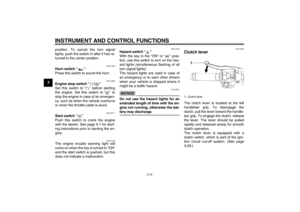 30
30 31
31 32
32 33
33 34
34 35
35 36
36 37
37 38
38 39
39 40
40 41
41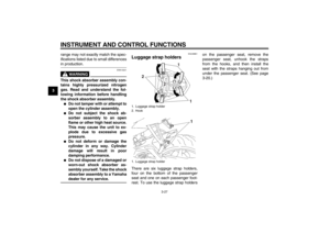 42
42 43
43 44
44 45
45 46
46 47
47 48
48 49
49 50
50 51
51 52
52 53
53 54
54 55
55 56
56 57
57 58
58 59
59 60
60 61
61 62
62 63
63 64
64 65
65 66
66 67
67 68
68 69
69 70
70 71
71 72
72 73
73 74
74 75
75 76
76 77
77 78
78 79
79 80
80 81
81 82
82 83
83 84
84 85
85 86
86 87
87 88
88 89
89 90
90 91
91 92
92 93
93 94
94 95
95 96
96 97
97 98
98 99
99 100
100 101
101 102
102 103
103 104
104 105
105 106
106 107
107 108
108 109
109 110
110 111
111