Page 81 of 112
![YAMAHA YZF-R6 2012 Owners Manual PERIODIC MAINTENANCE AND ADJUSTMENT
6-29
6
may contain substances that
could damage the O-rings.
[ECA11111]
EAU23095
Checking and lubricating the
cables The operation of all control cables and
the co](/manual-img/51/54369/w960_54369-80.png "YAMAHA YZF-R6 2012 Owners Manual PERIODIC MAINTENANCE AND ADJUSTMENT
6-29
6
may contain substances that
could damage the O-rings.
[ECA11111]
EAU23095
Checking and lubricating the
cables The operation of all control cables and
the co")
PERIODIC MAINTENANCE AND ADJUSTMENT
6-29
6
may contain substances that
could damage the O-rings.
[ECA11111]
EAU23095
Checking and lubricating the
cables The operation of all control cables and
the condition of the cables should be
checked before each ride, and the ca-
bles and cable ends should be lubricat-
ed if necessary. If a cable is damaged
or does not move smoothly, have a
Yamaha dealer check or replace it.
WARNING! Damage to the outer
housing of cables may result in in-
ternal rusting and cause interfer-
ence with cable movement. Replace
damaged cables as soon as possi-
ble to prevent unsafe conditions.[EWA10711] EAU23114
Checking and lubricating the
throttle grip and cable The operation of the throttle grip should
be checked before each ride. In addi-
tion, the cable should be lubricated by a
Yamaha dealer at the intervals speci-
fied in the periodic maintenance chart.
The throttle cable is equipped with a
rubber cover. Make sure that the cover
is securely installed. Even though the
cover is installed correctly, it does not
completely protect the cable from water
entry. Therefore, use care not to pour
water directly onto the cover or cable
when washing the vehicle. If the cable
or cover becomes dirty, wipe clean with
a moist cloth.
Recommended lubricant:
Yamaha Chain and Cable Lube or
engine oil
U1JSE0E0.book Page 29 Wednesday, July 27, 2011 10:34 AM
Page 82 of 112
PERIODIC MAINTENANCE AND ADJUSTMENT
6-30
6
EAU44273
Checking and lubricating the
brake and shift pedals The operation of the brake and shift
pedals should be checked before each
ride, and the pedal pivots should be lu-
bricated if necessary.Brake pedal
Shift pedal
EAU23142
Checking and lubricating the
brake and clutch levers Brake lever
Clutch lever
The operation of the brake and clutch
levers should be checked before each
ride, and the lever pivots should be lu-
bricated if necessary.
Recommended lubricant:
Lithium-soap-based grease
U1JSE0E0.book Page 30 Wednesday, July 27, 2011 10:34 AM
Page 83 of 112
PERIODIC MAINTENANCE AND ADJUSTMENT
6-31
6
EAU23202
Checking and lubricating the
sidestand The operation of the sidestand should
be checked before each ride, and the
sidestand pivot and metal-to-metal
contact surfaces should be lubricated if
necessary.
WARNING
EWA10731
If the sidestand does not move up
and down smoothly, have a Yamaha
dealer check or repair it. Otherwise,
the sidestand could contact the
ground and distract the operator, re-
sulting in a possible loss of control.
EAUM1652
Lubricating the swingarm piv-
ots The swingarm pivots must be lubricat-
ed by a Yamaha dealer at the intervals
specified in the periodic maintenance
and lubrication chart.
Recommended lubricants:Brake lever:
Silicone grease
Clutch lever:
Lithium-soap-based grease
Recommended lubricant: Lithium-soap-based grease
Recommended lubricant:Lithium-soap-based grease
U1JSE0E0.book Page 31 Wednesday, July 27, 2011 10:34 AM
Page 84 of 112

PERIODIC MAINTENANCE AND ADJUSTMENT
6-32
6
EAU23272
Checking the front fork The condition and operation of the front
fork must be checked as follows at the
intervals specified in the periodic main-
tenance and lubrication chart.
To check the condition
Check the inner tubes for scratches,
damage and excessive oil leakage.
To check the operation1. Place the vehicle on a level sur- face and hold it in an upright posi-
tion. WARNING! To avoid injury,
securely support the vehicle so
there is no danger of it falling
over.
[EWA10751]
2. While applying the front brake, push down hard on the handlebars
several times to check if the front
fork compresses and rebounds
smoothly.
NOTICE
ECA10590
If any damage is found or the front
fork does not operate smoothly,
have a Yamaha dealer check or re-
pair it.
EAU23283
Checking the steering Worn or loose steering bearings may
cause danger. Therefore, the operation
of the steering must be checked as fol-
lows at the intervals specified in the pe-
riodic maintenance and lubrication
chart.1. Place a stand under the engine to raise the front wheel off the
ground. (See page 6-39 for more
information.) WARNING! To
avoid injury, securely support
the vehicle so there is no danger
of it falling over.
[EWA10751]
2. Hold the lower ends of the front fork legs and try to move them for-
ward and backward. If any free
play can be felt, have a Yamaha
dealer check or repair the steering.
U1JSE0E0.book Page 32 Wednesday, July 27, 2011 10:34 AM
Page 85 of 112

PERIODIC MAINTENANCE AND ADJUSTMENT
6-33
6
EAU23291
Checking the wheel bearings The front and rear wheel bearings must
be checked at the intervals specified in
the periodic maintenance and lubrica-
tion chart. If there is play in the wheel
hub or if the wheel does not turn
smoothly, have a Yamaha dealer check
the wheel bearings.
EAU50210
Battery The battery is located under the rider
seat. (See page 3-20.)
This model is equipped with a VRLA
(Valve Regulated Lead Acid) battery.
There is no need to check the electro-
lyte or to add distilled water. However,
the battery lead connections need to be
checked and, if necessary, tightened.
WARNING
EWA10760
●
Electrolyte is poisonous and
dangerous since it contains sul-
furic acid, which causes severe
burns. Avoid any contact withskin, eyes or clothing and al-
ways shield your eyes when
working near batteries. In case
of contact, administer the fol-
lowing FIRST AID.
EXTERNAL: Flush with plenty of water.
INTERNAL: Drink large quan- tities of water or milk and im-
mediately call a physician.
EYES: Flush with water for 15 minutes and seek prompt
medical attention.
●
Batteries produce explosive hy-
drogen gas. Therefore, keep
sparks, flames, cigarettes, etc.,
away from the battery and pro-
vide sufficient ventilation when
charging it in an enclosed
space.
●
KEEP THIS AND ALL BATTER-
IES OUT OF THE REACH OF
CHILDREN.
To charge the battery
Have a Yamaha dealer charge the bat-
tery as soon as possible if it seems to
have discharged. Keep in mind that the
1. Battery
2. Negative battery lead (black)
3. Positive battery lead (red)
1
2
3
U1JSE0E0.book Page 33 Wednesday, July 27, 2011 10:34 AM
Page 86 of 112

PERIODIC MAINTENANCE AND ADJUSTMENT
6-34
6battery tends to discharge more quickly
if the vehicle is equipped with optional
electrical accessories.
NOTICE
ECA16521
To charge a VRLA (Valve Regulated
Lead Acid) battery, a special (con-
stant-voltage) battery charger is re-
quired. Using a conventional battery
charger will damage the battery.To store the battery
1. If the vehicle will not be used for more than one month, remove the
battery, fully charge it, and then
place it in a cool, dry place.
NOTICE: When removing the
battery, be sure the key is
turned to “OFF”, then discon-
nect the negative lead before
disconnecting the positive lead.
[ECA16302]
2. If the battery will be stored for more than two months, check it at least
once a month and fully charge it if
necessary.
3. Fully charge the battery before in- stallation. NOTICE: When install-
ing the battery, be sure the key is turned to “OFF”, then con-
nect the positive lead before
connecting the negative lead.
[ECA16840]
4. After installation, make sure that
the battery leads are properly con-
nected to the battery terminals.NOTICE
ECA16530
Always keep the battery charged.
Storing a discharged battery can
cause permanent battery damage.
EAU23706
Replacing the fuses The main fuse, the fuel injection system
fuse, and fuse box 1 are located under
the rider seat. (See page 3-20.)TIPTo access the fuel injection system
fuse, remove the starter relay cover by
pulling it upward.1. Main fuse
2. Fuel injection system spare fuse
3. Starter relay cover
4. Fuel injection system fuse
5. Fuse box 1
6. Backup fuse (for clock and immobilizer sys-tem)
7. Electronic throttle valve fuse
8. Spare fuse
2
1
5
6
3
748
U1JSE0E0.book Page 34 Wednesday, July 27, 2011 10:34 AM
Page 87 of 112

If a fuse is blown, replace it as follows.
1. Turn the key to “OFF” and turn off the electrical circ")
PERIODIC MAINTENANCE AND ADJUSTMENT
6-35
6
Fuse box 2 is located under panel A.
(See page 6-8.)
If a fuse is blown, replace it as follows.
1. Turn the key to “OFF” and turn off the electrical circuit in question.
2. Remove the blown fuse, and then install a new fuse of the specified
amperage. WARNING! Do not
use a fuse of a higher amperage
rating than recommended to avoid causing extensive dam-
age to the electrical system and
possibly a fire.
[EWA15131]
3. Turn the key to “ON” and turn on
the electrical circuit in question to
check if the device operates.
4. If the fuse immediately blows again, have a Yamaha dealer
check the electrical system.
EAU39013
Replacing a he adlight bulb This model is equipped with halogen
bulb headlights. If a headlight bulb
burns out, replace it as follows.NOTICE
ECA10650
Take care not to damage the follow-
ing parts:●
Headlight bulb
Do not touch the glass part of
the headlight bulb to keep it free
from oil, otherwise the transpar-
ency of the glass, the luminosity
of the bulb, and the bulb life will
be adversely affected. Thor-
oughly clean off any dirt and fin-
gerprints on the headlight bulb
using a cloth moistened with al-
cohol or thinner.
●
Headlight lens
Do not affix any type of tinted
film or stickers to the headlight
lens.
Do not use a headlight bulb of a
wattage higher than specified.
1. Fuse box 2
2. Left radiator fan fuse
3. Right radiator fan fuse
4. Signaling system fuse
5. Ignition fuse
6. Taillight fuse
7. Headlight fuse
8. Spare fuse
Specified fuses:
Main fuse:50.0 A
Fuel injection system fuse:
15.0 A
Electronic throttle valve fuse: 7.5 A
Backup fuse: 7.5 A
Radiator fan fuse:
15.0 A × 2
Ignition fuse: 15.0 A
Signaling system fuse: 10.0 A
Taillight fuse:
7.5 A
Headlight fuse: 15.0 A
U1JSE0E0.book Page 35 Wednesday, July 27, 2011 10:34 AM
Page 88 of 112
PERIODIC MAINTENANCE AND ADJUSTMENT
6-36
61. Remove the headlight bulb cover
by turning it counterclockwise.
2. Disconnect the headlight coupler. 3. Unhook the headlight bulb holder,
and then remove the burnt-out
bulb.
4. Place a new headlight bulb into po- sition, and then secure it with the
bulb holder.
5. Connect the headlight coupler. 6. Install the headlight bulb cover by
turning it clockwise.
7. Have a Yamaha dealer adjust the headlight beam if necessary.
1. Do not touch the glass part of the bulb.
1. Headlight bulb cover
1
1. Headlight coupler
1. Headlight bulb holder
U1JSE0E0.book Page 36 Wednesday, July 27, 2011 10:34 AM
 1
1 2
2 3
3 4
4 5
5 6
6 7
7 8
8 9
9 10
10 11
11 12
12 13
13 14
14 15
15 16
16 17
17 18
18 19
19 20
20 21
21 22
22 23
23 24
24 25
25 26
26 27
27 28
28 29
29 30
30 31
31 32
32 33
33 34
34 35
35 36
36 37
37 38
38 39
39 40
40 41
41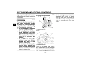 42
42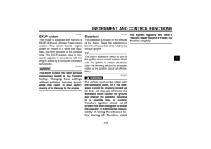 43
43 44
44 45
45 46
46 47
47 48
48 49
49 50
50 51
51 52
52 53
53 54
54 55
55 56
56 57
57 58
58 59
59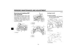 60
60 61
61 62
62 63
63 64
64 65
65 66
66 67
67 68
68 69
69 70
70 71
71 72
72 73
73 74
74 75
75 76
76 77
77 78
78 79
79 80
80 81
81 82
82 83
83 84
84 85
85 86
86 87
87 88
88 89
89 90
90 91
91 92
92 93
93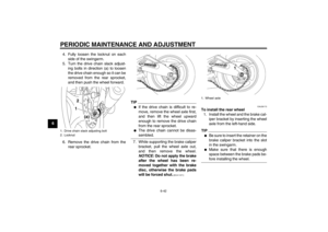 94
94 95
95 96
96 97
97 98
98 99
99 100
100 101
101 102
102 103
103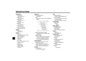 104
104 105
105 106
106 107
107 108
108 109
109 110
110 111
111

