Page 57 of 112

10 Drive chain Check")
PERIODIC MAINTENANCE AND ADJUSTMENT
6-5
6
9*Swingarm Check operation and for exces-
sive play. ŌłÜŌłÜŌłÜŌłÜ
Lubricate with lithium-soap-based grease. Every 50000 km (30000 mi)
10 Drive chain Check chain slack, alignment and
condition.
Adjust and lubricate chain with a special O-ring chain lubricant
thoroughly. Every 800 km (500 mi) and after washing the motorcycle, riding in the rain or
riding in wet areas
11 *Steering bearings Check bearing play and steering
for roughness. ŌłÜŌłÜŌłÜŌłÜŌłÜ
Lubricate with lithium-soap-based grease. Every 20000 km (12000 mi)
12 *Chassis fasteners Make sure that all nuts, bolts and
screws are properly tightened. ŌłÜŌłÜŌłÜŌłÜŌłÜ
13 Brake lever pivot
shaft Lubricate with silicone grease.
ŌłÜŌłÜŌłÜŌłÜŌłÜ
14 Brake pedal pivot
shaft Lubricate with lithium-soap-based
grease. ŌłÜŌłÜŌłÜŌłÜŌłÜ
15 Clutch lever pivot
shaft Lubricate with lithium-soap-based
grease. ŌłÜŌłÜŌłÜŌłÜŌłÜ
16 Shift pedal pivot
shaft Lubricate with lithium-soap-based
grease. ŌłÜŌłÜŌłÜŌłÜŌłÜ
17 Sidestand Check operation.
Lubricate with lithium-soap-based
grease. ŌłÜŌłÜŌłÜŌłÜŌłÜ
18 *Sidestand switch Check operation. ŌłÜŌłÜŌłÜŌłÜŌłÜŌłÜ
NO. ITEM CHECK OR MAINTENANCE JOB
ODOMETER READING
ANNUAL
CHECK
1000 km
(600 mi) 10000 km
(6000 mi) 20000 km
(12000 mi) 30000 km
(18000 mi) 40000 km
(24000 mi)
U1JSE0E0.book Page 5 Wednesday, July 27, 2011 10:34 AM
Page 58 of 112

PERIODIC MAINTENANCE AND ADJUSTMENT
6-6
6
19*Front fork Check operation and for oil leak-
age. ŌłÜŌłÜŌłÜŌłÜ
20 *Shock absorber as-
sembly Check operation and shock ab-
sorber for oil leakage. ŌłÜŌłÜŌłÜŌłÜ
21 *Rear suspension re-
lay arm and con-
necting arm
pivoting points Check operation.
ŌłÜŌłÜŌłÜŌłÜ
22 Engine oil Change.
Check oil level and vehicle for oil
leakage. ŌłÜŌłÜŌłÜŌłÜŌłÜŌłÜ
23 Engine oil filter car-
tridge
Replace.
ŌłÜŌłÜŌłÜ
24 *Cooling system Check coolant level and vehicle
for coolant leakage. ŌłÜŌłÜŌłÜŌłÜŌłÜ
Change with ethylene glycol anti- freeze coolant. Every 3 years
25 *Front and rear brake
switches
Check operation.
ŌłÜŌłÜŌłÜŌłÜŌłÜŌłÜ
26 Moving parts and
cables
Lubricate.
ŌłÜŌłÜŌłÜŌłÜŌłÜ
27 *Throttle grip Check operation.
Check throttle grip free play, and
adjust if necessary.
Lubricate cable and grip housing. ŌłÜŌłÜŌłÜŌłÜŌłÜ
28 *Lights, signals and
switches Check operation.
Adjust headlight beam.
ŌłÜŌłÜŌłÜŌłÜŌłÜŌłÜ
NO. ITEM CHECK OR MAINTENANCE JOB
ODOMETER READING
ANNUAL
CHECK
1000 km
(600 mi) 10000 km
(6000 mi) 20000 km
(12000 mi) 30000 km
(18000 mi) 40000 km
(24000 mi)U1JSE0E0.book Page 6 Wednesday, July 27, 2011 10:34 AM
Page 59 of 112
PERIODIC MAINTENANCE AND ADJUSTMENT
6-7
6
EAU18680
TIPŌŚÅ
Air filter This modelŌĆÖs air filter is equipped with a disposable oil-coated paper element, which must not be cleaned with com- pressed air to avoid damaging it.
The air filter element needs to be replaced more frequently when riding in unusually wet or dusty areas.
ŌŚÅ
Hydraulic brake service Regularly check and, if necessary, correct the brake fluid level.
Every two years replace the internal components of the brake master cylinders and calipers, and change the brake fluid.
Replace the brake hoses every four years and if cracked or damaged.
U1JSE0E0.book Page 7 Wednesday, July 27, 2011 10:34 AM
Page 60 of 112
PERIODIC MAINTENANCE AND ADJUSTMENT
6-8
6
EAU18712
Removing and installing cowl-
ings and panels The cowlings and panels shown need
to be removed to perform some of the
maintenance jobs described in this
chapter. Refer to this section each time
a cowling or panel needs to be re-
moved and installed.
EAU44932
Cowlings A and B
To remove a cowling1. Remove the bolts, quick fasteners,and quick fastener screw.
1. Cowling A
1. Cowling B
2. Cowling C
1. Panel A
2. Panel B
2
1
1. Cowling A
2. Bolt
3. Quick fastener
1. Quick fastener
2 3
1 2
2
2
U1JSE0E0.book Page 8 Wednesday, July 27, 2011 10:34 AM
Page 61 of 112
PERIODIC MAINTENANCE AND ADJUSTMENT
6-9
6
2. Remove the projection on cowling A from the hole in cowling B as
shown. 3. Remove the forward-most projec-
tion from the slot, slide the cowling
forward, and then remove the re-
maining projections from the slots
as shown.
4. Disconnect the turn signal light lead coupler.
1. Quick fastener
2. Quick fastener screw
1. Cowling B
2. Bolt
3. Quick fastener
1. Quick fastener
1. Quick fastener
2. Quick fastener screw
1. Cowling A
2. Cowling B
U1JSE0E0.book Page 9 Wednesday, July 27, 2011 10:34 AM
Page 62 of 112
PERIODIC MAINTENANCE AND ADJUSTMENT
6-10
6To install a cowling
1. Connect the turn signal light leadcoupler. 2. Fit the projections into the slots,
slide the cowling rearward, and
then fit the forward-most projection
into the slot. 3. Fit the projection on cowling A into
the hole in cowling B as shown.
4. Install the bolts, quick fasteners, and quick fastener screw.
EAU39092
Cowling C
To remove the cowling1. Remove cowling B and panel B.(See page 6-8.)
2. Unfasten the wire harness by pressing on the projection to open
the plastic fastener.
1. Cowling A
2. Turn signal light lead coupler
1. Cowling B
2. Turn signal light lead coupler
1. Cowling A
2. Turn signal light lead coupler
1. Cowling B
2. Turn signal light lead coupler
1. Cowling A
2. Cowling B
U1JSE0E0.book Page 10 Wednesday, July 27, 2011 10:34 AM
Page 63 of 112
PERIODIC MAINTENANCE AND ADJUSTMENT
6-11
6
3. Remove the bolts and the quick
fastener, and then pull the cowling
off as shown. To install the cowling
1. Fit the slot in cowling C over the
projection on the front cowling.
2. Install the bolts and the quick fas- tener.
3. Place the wire harness in the orig- inal position, and then close the
plastic fastener.
4. Install the cowling and the panel.
EAU39062
Panels A and B
To remove a panelRemove the bolts, and then pull the
panel off as shown. To install a panel
Place the panel in the original position,
and then install the bolts.
1. Plastic fastener
2. Projection
3. Wire harness
1. Cowling C
2. Bolt
3. Quick fastener
1. Cowling C
2. Slot
3. Front cowling
4. Projection
1. Panel B
2. Bolt
U1JSE0E0.book Page 11 Wednesday, July 27, 2011 10:34 AM
Page 64 of 112

PERIODIC MAINTENANCE AND ADJUSTMENT
6-12
6
EAU19652
Checking the spark plugs The spark plugs are important engine
components, which should be checked
periodically, preferably by a Yamaha
dealer. Since heat and deposits will
cause any spark plug to slowly erode,
they should be removed and checked
in accordance with the periodic mainte-
nance and lubrication chart. In addition,
the condition of the spark plugs can re-
veal the condition of the engine.
The porcelain insulator around the cen-
ter electrode of each spark plug should
be a medium-to-light tan (the ideal color
when the vehicle is ridden normally),
and all spark plugs installed in the en-
gine should have the same color. If any
spark plug shows a distinctly different
color, the engine could be operating im-
properly. Do not attempt to diagnose
such problems yourself. Instead, have
a Yamaha dealer check the vehicle.
If a spark plug shows signs of electrode
erosion and excessive carbon or other
deposits, it should be replaced.Before installing a spark plug, the spark
plug gap should be measured with a
wire thickness gauge and, if necessary,
adjusted to specification.
Clean the surface of the spark plug
gasket and its mating surface, and then
wipe off any grime from the spark plug
threads.
TIPIf a torque wrench is not available when
installing a spark plug, a good estimate
of the correct torque is 1/4ŌĆō1/2 turn
past finger tight. However, the spark
plug should be tightened to the speci-
fied torque as soon as possible.NOTICE
ECA10840
Do not use any tools to remove or in-
stall the spark plug cap, otherwise
the ignition coil coupler may get
damaged. The spark plug cap may
be difficult to remove because the
rubber seal on the end of the cap fits
tightly. To remove the spark plug
cap, simply twist it back and forth
while pulling it out; to install it, twist
it back and forth while pushing it in.
Specified spark plug:
NGK/CR10EK
1. Spark plug gapSpark plug gap:0.6ŌĆō0.7 mm (0.024ŌĆō0.028 in)
Tightening torque: Spark plug:13 Nm (1.3 m┬Ękgf, 9.4 ft┬Ęlbf)
1
1
U1JSE0E0.book Page 12 Wednesday, July 27, 2011 10:34 AM
 1
1 2
2 3
3 4
4 5
5 6
6 7
7 8
8 9
9 10
10 11
11 12
12 13
13 14
14 15
15 16
16 17
17 18
18 19
19 20
20 21
21 22
22 23
23 24
24 25
25 26
26 27
27 28
28 29
29 30
30 31
31 32
32 33
33 34
34 35
35 36
36 37
37 38
38 39
39 40
40 41
41 42
42 43
43 44
44 45
45 46
46 47
47 48
48 49
49 50
50 51
51 52
52 53
53 54
54 55
55 56
56 57
57 58
58 59
59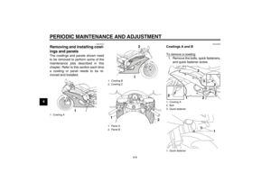 60
60 61
61 62
62 63
63 64
64 65
65 66
66 67
67 68
68 69
69 70
70 71
71 72
72 73
73 74
74 75
75 76
76 77
77 78
78 79
79 80
80 81
81 82
82 83
83 84
84 85
85 86
86 87
87 88
88 89
89 90
90 91
91 92
92 93
93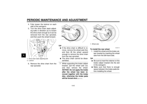 94
94 95
95 96
96 97
97 98
98 99
99 100
100 101
101 102
102 103
103 104
104 105
105 106
106 107
107 108
108 109
109 110
110 111
111


