Page 73 of 112

PERIODIC MAINTENANCE AND ADJUSTMENT
6-21
6
Tire inspection
The tires must be checked before each
ride. If the center tread depth reaches
the specified limit, if the tire has a nail or
glass fragments in it, or if the sidewall is
cracked, have a Yamaha dealer re-
place the tire immediately.
TIPThe tire tread depth limits may differ
from country to country. Always comply
with the local regulations.
WARNING
EWA10471
●
Have a Yamaha dealer replace
excessively worn tires. Besides
being illegal, operating the vehi-
cle with excessively worn tires
decreases riding stability and
can lead to loss of control.
●
The replacement of all wheel
and brake-related parts, includ-
ing the tires, should be left to a
Yamaha dealer, who has the necessary professional knowl-
edge and experience to do so.
●
Ride at moderate speeds after
changing a tire since the tire
surface must first be “broken
in” for it to develop its optimal
characteristics.
Tire information
This motorcycle is equipped with tube-
less tires, tire air valves and cast
wheels.
WARNING
EWA10481
●
The front and rear tires should
be of the same make and de-
sign, otherwise the handling
characteristics of the motorcy-
cle may be different, which
could lead to an accident.
●
Always make sure that the valve
caps are securely installed to
prevent air pressure leakage.
1. Tire sidewall
2. Tire tread depthMinimum tire tread depth (front and
rear): 1.6 mm (0.06 in)
1. Tire air valve
2. Tire air valve core
3. Tire air valve cap with seal
U1JSE0E0.book Page 21 Wednesday, July 27, 2011 10:34 AM
Page 74 of 112

PERIODIC MAINTENANCE AND ADJUSTMENT
6-22
6
●
Use only the tire valves and
valve cores listed below to
avoid tire deflation during a
high-speed ride.
After extensive tests, only the tires list-
ed below have been approved for this
model by Yamaha Motor Co., Ltd.
WARNING
EWA10600
This motorcycle is fitted with super-
high-speed tires. Note the following
points in order to make the most ef-
ficient use of these tires.●
Use only the specified replace-
ment tires. Other tires may run
the danger of bursting at super
high speeds.
●
Brand-new tires can have a rela-
tively poor grip on certain road
surfaces until they have been
“broken in”. Therefore, it is ad-
visable before doing any high-
speed riding to ride conserva-
tively for approximately 100 km
(60 mi) after installing a new tire.
●
The tires must be warmed up
before a high-speed run.
●
Always adjust the tire air pres-
sure according to the operating
conditions.
EAU21962
Cast wheels To maximize the performance, durabil-
ity, and safe operation of your vehicle,
note the following points regarding the
specified wheels.●
The wheel rims should be checked
for cracks, bends, warpage or oth-
er damage before each ride. If any
damage is found, have a Yamaha
dealer replace the wheel. Do not
attempt even the smallest repair to
the wheel. A deformed or cracked
wheel must be replaced.
●
The wheel should be balanced
whenever either the tire or wheel
has been changed or replaced. An
unbalanced wheel can result in
poor performance, adverse han-
dling characteristics, and a short-
ened tire life.
Front tire:Size:120/70 ZR17M/C (58W)
Manufacturer/model: BRIDGESTONE/BT016F F
DUNLOP/Qualifier PT M
Rear tire: Size:180/55 ZR17M/C (73W)
Manufacturer/model: BRIDGESTONE/BT016R F
DUNLOP/Qualifier PT M
FRONT and REAR: Tire air valve:TR412
Va l ve c o r e : #9100 (original)
U1JSE0E0.book Page 22 Wednesday, July 27, 2011 10:34 AM
Page 75 of 112
 as
shown. Periodically check the c")
PERIODIC MAINTENANCE AND ADJUSTMENT
6-23
6
EAU33891
Adjusting the clutch lever free
play The clutch lever free play should mea-
sure 10.0–15.0 mm (0.39–0.59 in) as
shown. Periodically check the clutch le-
ver free play and, if necessary, adjust it
as follows.
To increase the clutch lever free play,
turn the clutch lever free play adjusting
bolt at the clutch lever in direction (a).
To decrease the clutch lever free play,
turn the adjusting bolt in direction (b).
TIPIf the specified clutch lever free play
cannot be obtained as described
above, proceed as follows.1. Fully turn the adjusting bolt at theclutch lever in direction (a) to loos-
en the clutch cable.
2. Loosen the locknut at the crank- case.
3. To increase the clutch lever free play, turn the clutch lever free play
adjusting nut in direction (a). To
decrease the clutch lever free play,
turn the adjusting nut in direction
(b).
4. Tighten the locknut.
EAU37913
Checking the brake lever free
play There should be no free play at the
brake lever end. If there is free play,
have a Yamaha dealer inspect the
brake system.
WARNING
EWA14211
A soft or spongy feeling in the brake
lever can indicate the presence of air
in the hydraulic system. If there is air
in the hydraulic system, have a
Yamaha dealer bleed the system be-
fore operating the vehicle. Air in the
hydraulic system will diminish the
1. Clutch lever free play adjusting bolt
2. Clutch lever free play
1. Locknut
2. Clutch lever free play adjusting nut
1. No brake lever free play
1
U1JSE0E0.book Page 23 Wednesday, July 27, 2011 10:34 AM
Page 76 of 112

PERIODIC MAINTENANCE AND ADJUSTMENT
6-24
6braking performance, which may re-
sult in loss of control and an acci-
dent.
EAU22273
Brake light switches The brake light, which is activated by
the brake pedal and brake lever, should
come on just before braking takes ef-
fect. If necessary, adjust the rear brake
light switch as follows, but the front
brake light switch should be adjusted
by a Yamaha dealer.
Turn the rear brake light switch adjust-
ing nut while holding the rear brake light
switch in place. To make the brake light
come on earlier, turn the adjusting nut
in direction (a). To make the brake light
come on later, turn the adjusting nut in
direction (b).
EAU22392
Checking the front and rear
brake pads The front and rear brake pads must be
checked for wear at the intervals spec-
ified in the periodic maintenance and
lubrication chart.
EAU36890
Front brake pads
Each front brake pad is provided with
wear indicators, which allows you to
check the brake pad wear without hav-
ing to disassemble the brake. To check
the brake pad wear, check the position
of the wear indicators while applying
the brake. If a brake pad has worn to
1. Rear brake light switch
2. Rear brake light switch adjusting nut
2
(b)
(a)
1
1. Brake pad wear indicator
U1JSE0E0.book Page 24 Wednesday, July 27, 2011 10:34 AM
Page 77 of 112

PERIODIC MAINTENANCE AND ADJUSTMENT
6-25
6
the point that a wear indicator almost
touches the brake disc, have a Yamaha
dealer replace the brake pads as a set.
EAU46291
Rear brake pads
Each rear brake pad is provided with
wear indicator grooves, which allow
you to check the brake pad wear with-
out having to disassemble the brake.
To check the brake pad wear, check
the wear indicator grooves. If a brake
pad has worn to the point that a wear
indicator groove almost appears, have
a Yamaha dealer replace the brake
pads as a set.
EAU22581
Checking the brake fluid level Before riding, check that the brake fluid
is above the minimum level mark.
Check the brake fluid level with the top
of the reservoir level. Replenish the
brake fluid if necessary.
Front brake
Rear brake
WARNING
EWA15990
Improper maintenance can result in
loss of braking ability. Observe
these precautions:●
Insufficient brake fluid may al-
low air to enter the brake sys-
tem, reducing braking
performance.
●
Clean the filler cap before re-
moving. Use only DOT 4 brake
fluid from a sealed container.
1. Brake pad wear indicator groove
1
1
1. Minimum level mark
1. Minimum level mark
Specified brake fluid:
DOT 4
U1JSE0E0.book Page 25 Wednesday, July 27, 2011 10:34 AM
Page 78 of 112

PERIODIC MAINTENANCE AND ADJUSTMENT
6-26
6
●
Use only the specified brake flu-
id; otherwise, the rubber seals
may deteriorate, causing leak-
age.
●
Refill with the same type of
brake fluid. Adding a brake fluid
other than DOT 4 may result in a
harmful chemical reaction.
●
Be careful that water does not
enter the brake fluid reservoir
when refilling. Water will signifi-
cantly lower the boiling point of
the fluid and may result in vapor
lock.
NOTICE
ECA17640
Brake fluid may damage painted sur-
faces or plastic parts. Always clean
up spilled fluid immediately.As the brake pads wear, it is normal for
the brake fluid level to gradually go
down. A low brake fluid level may indi-
cate worn brake pads and/or brake sys-
tem leakage; therefore, be sure to
check the brake pads for wear and the
brake system for leakage. If the brakefluid level goes down suddenly, have a
Yamaha dealer check the cause before further riding.
EAU22731
Changing the brake fluid Have a Yamaha dealer change the
brake fluid at the intervals specified in
the TIP after the periodic maintenance
and lubrication chart. In addition, have
the oil seals of the master cylinders and
calipers as well as the brake hoses re-
placed at the intervals listed below or
whenever they are damaged or leak-
ing.●
Oil seals: Replace every two
years.
●
Brake hoses: Replace every four
years.
U1JSE0E0.book Page 26 Wednesday, July 27, 2011 10:34 AM
Page 79 of 112

PERIODIC MAINTENANCE AND ADJUSTMENT
6-27
6
EAU22760
Drive chain slack The drive chain slack should be
checked before each ride and adjusted
if necessary.
EAU22774
To check the drive chain slack1. Place the motorcycle on the side- stand.TIPWhen checking and adjusting the drive
chain slack, there should be no weight
on the motorcycle.2. Shift the transmission into the neu- tral position.
3. Measure the drive chain slack as shown. 4. If the drive chain slack is incorrect,
adjust it as follows.
EAU39056
To adjust the drive chain slack
Consult a Yamaha dealer before ad-
justing the drive chain slack.1. Loosen the axle nut and the lock- nut on each side of the swingarm. 2. To tighten the drive chain, turn the
drive chain slack adjusting bolt on
each side of the swingarm in direc-
tion (a). To loosen the drive chain,
turn the adjusting bolt on each side
of the swingarm in direction (b),
and then push the rear wheel for-
ward. NOTICE: Improper drive
chain slack will overload the en-
gine as well as other vital parts
of the motorcycle and can lead
to chain slippage or breakage.
Drive chain slack: 30.0–45.0 mm (1.18–1.77 in)
1. Drive chain slack
1. Drive chain slack adjusting bolt
2. Locknut
3. Alignment marks
4. Axle nut
5. Drive chain puller
45
1
2
3
U1JSE0E0.book Page 27 Wednesday, July 27, 2011 10:34 AM
Page 80 of 112
![YAMAHA YZF-R6 2012 Owners Manual PERIODIC MAINTENANCE AND ADJUSTMENT
6-28
6To prevent this from occurring,
keep the drive chain slack with-
in the specified limits.
[ECA10571]
TIPUsing the alignment marks on each
drive chain puller,](/manual-img/51/54369/w960_54369-79.png "YAMAHA YZF-R6 2012 Owners Manual PERIODIC MAINTENANCE AND ADJUSTMENT
6-28
6To prevent this from occurring,
keep the drive chain slack with-
in the specified limits.
[ECA10571]
TIPUsing the alignment marks on each
drive chain puller,")
PERIODIC MAINTENANCE AND ADJUSTMENT
6-28
6To prevent this from occurring,
keep the drive chain slack with-
in the specified limits.
[ECA10571]
TIPUsing the alignment marks on each
drive chain puller, make sure that both
chain pullers are in the same position
for proper wheel alignment. Use the
end of the swingarm as the reference
point for the alignment marks.3. Tighten the axle nut to the speci-
fied torque. 4. Tighten the adjusting bolts in direc-
tion (a) to their specified torque.
5. Tighten the locknuts to their speci- fied torque.
6. Make sure that the drive chain pull- ers are in the same position, the
drive chain slack is correct, and
the drive chain moves smoothly.
EAU23025
Cleaning and lubricating the
drive chain The drive chain must be cleaned and
lubricated at the intervals specified in
the periodic maintenance and lubrica-
tion chart, otherwise it will quickly wear
out, especially when riding in dusty or
wet areas. Service the drive chain as
follows.NOTICE
ECA10583
The drive chain must be lubricated
after washing the motorcycle, riding
in the rain or riding in wet areas.1. Clean the drive chain with kero-sene and a small soft brush.
NOTICE: To prevent damaging
the O-rings, do not clean the
drive chain with steam cleaners,
high-pressure washers or inap-
propriate solvents.
[ECA11121]
2. Wipe the drive chain dry.
3. Thoroughly lubricate the drive chain with a special O-ring chain
lubricant. NOTICE: Do not use
engine oil or any other lubri-
cants for the drive chain, as they
1. Drive chain slack adjusting bolt
2. LocknutTightening torque: Axle nut:110 Nm (11 m·kgf, 80 ft·lbf)
(a)
(b)
12
Tightening torque:
Drive chain slack adjusting bolt:2.0 Nm (0.20 m·kgf, 1.4 ft·lbf)
Tightening torque: Locknut:16 Nm (1.6 m·kgf, 12 ft·lbf)
U1JSE0E0.book Page 28 Wednesday, July 27, 2011 10:34 AM
 1
1 2
2 3
3 4
4 5
5 6
6 7
7 8
8 9
9 10
10 11
11 12
12 13
13 14
14 15
15 16
16 17
17 18
18 19
19 20
20 21
21 22
22 23
23 24
24 25
25 26
26 27
27 28
28 29
29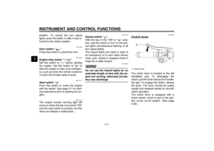 30
30 31
31 32
32 33
33 34
34 35
35 36
36 37
37 38
38 39
39 40
40 41
41 42
42 43
43 44
44 45
45 46
46 47
47 48
48 49
49 50
50 51
51 52
52 53
53 54
54 55
55 56
56 57
57 58
58 59
59 60
60 61
61 62
62 63
63 64
64 65
65 66
66 67
67 68
68 69
69 70
70 71
71 72
72 73
73 74
74 75
75 76
76 77
77 78
78 79
79 80
80 81
81 82
82 83
83 84
84 85
85 86
86 87
87 88
88 89
89 90
90 91
91 92
92 93
93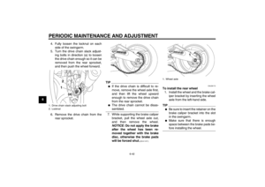 94
94 95
95 96
96 97
97 98
98 99
99 100
100 101
101 102
102 103
103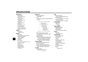 104
104 105
105 106
106 107
107 108
108 109
109 110
110 111
111