Page 89 of 112
PERIODIC MAINTENANCE AND ADJUSTMENT
6-37
6
EAU24181
Tail/brake light This model is equipped with an LED-
type tail/brake light.
If the tail/brake light does not come on,
have a Yamaha dealer check it.
EAU24204
Replacing a turn signal light
bulb 1. Remove the turn signal light lensby removing the screw.
2. Remove the burnt-out bulb by pushing it in and turning it counter-
clockwise. 3. Insert a new bulb into the socket,
push it in, and then turn it clock-
wise until it stops.
4. Install the lens by installing the screw. NOTICE: Do not over-
tighten the screw, otherwise the
lens may break.
[ECA11191]
1. Turn signal light lens
2. Screw
21
1. Turn signal light bulb
U1JSE0E0.book Page 37 Wednesday, July 27, 2011 10:34 AM
Page 90 of 112
PERIODIC MAINTENANCE AND ADJUSTMENT
6-38
6
EAU24313
Replacing the license plate
light bulb 1. Remove the license plate light unitby removing the screws.
2. Remove the license plate light bulb socket (together with the bulb) by
pulling it out. 3. Remove the burnt-out bulb by pull-
ing it out.
4. Insert a new bulb into the socket.
5. Install the socket (together with the bulb) by pushing it in.
6. Install the license plate light unit by installing the screws.
EAU44940
Auxiliary light This model is equipped with an LED-
type auxiliary light.
If the auxiliary light does not come on,
have a Yamaha dealer check it.
1. Screw
2. License plate light unit
1
2
1. License plate light bulb
2. License plate light bulb socket
1
2
1. Auxiliary light
U1JSE0E0.book Page 38 Wednesday, July 27, 2011 10:34 AM
Page 91 of 112

PERIODIC MAINTENANCE AND ADJUSTMENT
6-39
6
EAU24350
Supporting the motorcycle Since this model is not equipped with a
centerstand, follow these precautions
when removing the front and rear
wheel or performing other maintenance
requiring the motorcycle to stand up-
right. Check that the motorcycle is in a
stable and level position before starting
any maintenance. A strong wooden
box can be placed under the engine for
added stability.
To service the front wheel1. Stabilize the rear of the motorcycle by using a motorcycle stand or, if
an additional motorcycle stand is
not available, by placing a jack un-
der the frame in front of the rear
wheel.
2. Raise the front wheel off the ground by using a motorcycle
stand.
To service the rear wheel
Raise the rear wheel off the ground by
using a motorcycle stand or, if a motor-
cycle stand is not available, by placing a jack either under each side of the
frame in front of the rear wheel or under
each side of the swingarm.
EAU24360
Front wheel
EAU33925
To remove the front wheel
WARNING
EWA10821
To avoid injury, securely support the
vehicle so there is no danger of it
falling over.1. Loosen the front wheel axle pinch
bolts, the axle bolt, and then the
brake caliper bolts.
2. Lift the front wheel off the ground according to the procedure in the
previous section “Supporting the
motorcycle”.1. Front wheel axle pinch bolt
U1JSE0E0.book Page 39 Wednesday, July 27, 2011 10:34 AM
Page 92 of 112

PERIODIC MAINTENANCE AND ADJUSTMENT
6-40
63. Remove the brake hose holder on
each side by removing the bolt and
nut.
4. Remove the brake caliper on each side by removing the bolts.
5. Remove the axle bolt, push the wheel axle from the left side to re-
move it, and then remove the
wheel. NOTICE: Do not apply the
brake after the brake calipers
have been removed, otherwise
the brake pads will be forced
shut.
[ECA11051] EAU33935
To install the front wheel
1. Lift the wheel up between the fork legs.
2. Insert the wheel axle.
3. Install the axle bolt, lower the front wheel so that it is on the ground,
and then put the sidestand down.
4. Install the brake caliper on each side by installing the bolts, and
then tightening them to the speci-
fied torque.TIPMake sure that there is enough space
between the brake pads before install-
ing the brake calipers onto the brake
discs.
5. Install the brake hose holder oneach side by installing the bolt and
nut.
6. Tighten the axle bolt to the speci- fied torque.TIPWhile tightening the axle bolt, hold the
wheel axle with a 19-mm hexagon
wrench to keep it from turning.7. Tighten wheel axle pinch bolt B,then pinch bolt A to the specified
torque.
1. Brake hose holder
2. Bolt and nut
3. Brake caliper bolt
4. Brake caliper
5. Axle bolt
31
2
4
5
1. Wheel axle
Tightening torque:Brake caliper bolt:
35 Nm (3.5 m·kgf, 25 ft·lbf)
Tightening torque: Axle bolt:91 Nm (9.1 m·kgf, 66 ft·lbf)
U1JSE0E0.book Page 40 Wednesday, July 27, 2011 10:34 AM
Page 93 of 112

PERIODIC MAINTENANCE AND ADJUSTMENT
6-41
6
8. Retighten pinch bolt B to the spec-
ified torque.
9. Tap the outer side of the right fork leg with a rubber mallet to align it
with the end of the wheel axle.
10. Tighten wheel axle pinch bolt D, then pinch bolt C to the specified
torque.
11. Retighten pinch bolt D to the spec- ified torque. 12. While applying the front brake,
push down hard on the handlebar
several times to check for proper
fork operation.
EAU25080
Rear wheel
EAU44953
To remove the rear wheel
WARNING
EWA10821
To avoid injury, securely support the
vehicle so there is no danger of it
falling over.1. Loosen the axle nut.
2. Lift the rear wheel off the groundaccording to the procedure on
page 6-39.
3. Remove the axle nut.
1. Front wheel axle pinch bolt A
2. Front wheel axle pinch bolt B
3. Front wheel axle pinch bolt C
4. Front wheel axle pinch bolt DTightening torque: Wheel axle pinch bolt:21 Nm (2.1 m·kgf, 15 ft·lbf)
Tightening torque: Wheel axle pinch bolt:
21 Nm (2.1 m·kgf, 15 ft·lbf)
1. Axle nut
2. Brake caliper
3. Brake caliper bracket
1
2
3
U1JSE0E0.book Page 41 Wednesday, July 27, 2011 10:34 AM
Page 94 of 112
 to loosen
the drive chain enough so")
PERIODIC MAINTENANCE AND ADJUSTMENT
6-42
64. Fully loosen the locknut on each
side of the swingarm.
5. Turn the drive chain slack adjust- ing bolts in direction (a) to loosen
the drive chain enough so it can be
removed from the rear sprocket,
and then push the wheel forward.
6. Remove the drive chain from the rear sprocket.
TIP●
If the drive chain is difficult to re-
move, remove the wheel axle first,
and then lift the wheel upward
enough to remove the drive chain
from the rear sprocket.
●
The drive chain cannot be disas-
sembled.
7. While supporting the brake caliperbracket, pull the wheel axle out,
and then remove the wheel.
NOTICE: Do not apply the brake
after the wheel has been re-
moved together with the brake
disc, otherwise the brake pads
will be forced shut.
[ECA11071] EAU39173
To install the rear wheel
1. Install the wheel and the brake cal- iper bracket by inserting the wheel
axle from the left-hand side.TIP●
Be sure to insert the retainer on the
brake caliper bracket into the slot
in the swingarm.
●
Make sure that there is enough
space between the brake pads be-
fore installing the wheel.
1. Drive chain slack adjusting bolt
2. Locknut
(a)
12
1. Wheel axle
U1JSE0E0.book Page 42 Wednesday, July 27, 2011 10:34 AM
Page 95 of 112

PERIODIC MAINTENANCE AND ADJUSTMENT
6-43
6
2. Install the drive chain onto the rear
sprocket.
3. Install the axle nut, and then lower the rear wheel so that it is on the
ground, and then put the sidestand
down.
4. Adjust the drive chain slack. (See page 6-27.)
5. Tighten the axle nut to the speci- fied torque.
6. Tighten the drive chain slack ad- justing bolts in direction (b) to their
specified torque. 7. Tighten the locknuts to their speci-
fied torque.
EAU25871
Troubleshooting Although Yamaha motorcycles receive
a thorough inspection before shipment
from the factory, trouble may occur dur-
ing operation. Any problem in the fuel,
compression, or ignition systems, for
example, can cause poor starting and
loss of power.
The following troubleshooting charts
represent quick and easy procedures
for checking these vital systems your-
self. However, should your motorcycle
require any repair, take it to a Yamaha
dealer, whose skilled technicians have
the necessary tools, experience, and
know-how to service the motorcycle
properly.
Use only genuine Yamaha replace-
ment parts. Imitation parts may look like
Yamaha parts, but they are often inferi-
or, have a shorter service life and can
lead to expensive repair bills.
WARNING
EWA15141
When checking the fuel system, do
not smoke, and make sure there are
no open flames or sparks in the ar-
ea, including pilot lights from water
1. Retainer
2. SlotTightening torque:Axle nut:110 Nm (11 m·kgf, 80 ft·lbf)
1. Drive chain slack adjusting bolt
Tightening torque: Drive chain slack adjusting bolt:2.0 Nm (0.20 m·kgf, 1.4 ft·lbf)
Tightening torque: Locknut:
16 Nm (1.6 m·kgf, 12 ft·lbf)
(b)
1
U1JSE0E0.book Page 43 Wednesday, July 27, 2011 10:34 AM
Page 96 of 112
PERIODIC MAINTENANCE AND ADJUSTMENT
6-44
6heaters or furnaces. Gasoline or
gasoline vapors can ignite or ex-
plode, causing severe injury or
property damage.
U1JSE0E0.book Page 44 Wednesday, July 27, 2011 10:34 AM
 1
1 2
2 3
3 4
4 5
5 6
6 7
7 8
8 9
9 10
10 11
11 12
12 13
13 14
14 15
15 16
16 17
17 18
18 19
19 20
20 21
21 22
22 23
23 24
24 25
25 26
26 27
27 28
28 29
29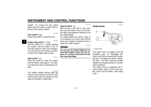 30
30 31
31 32
32 33
33 34
34 35
35 36
36 37
37 38
38 39
39 40
40 41
41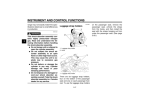 42
42 43
43 44
44 45
45 46
46 47
47 48
48 49
49 50
50 51
51 52
52 53
53 54
54 55
55 56
56 57
57 58
58 59
59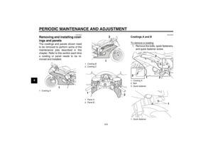 60
60 61
61 62
62 63
63 64
64 65
65 66
66 67
67 68
68 69
69 70
70 71
71 72
72 73
73 74
74 75
75 76
76 77
77 78
78 79
79 80
80 81
81 82
82 83
83 84
84 85
85 86
86 87
87 88
88 89
89 90
90 91
91 92
92 93
93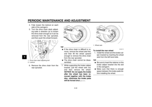 94
94 95
95 96
96 97
97 98
98 99
99 100
100 101
101 102
102 103
103 104
104 105
105 106
106 107
107 108
108 109
109 110
110 111
111

