2012 SSANGYONG NEW ACTYON SPORTS light
[x] Cancel search: lightPage 268 of 828

10-71413-00
4) Operation
Glow plug is installed in the cylinder head. It enhances the cold starting performance and reduces
the exhaust gas during cold starting.
(1) Operation
Duty control area:
Between 5 and 100%
Frequency: 20 Hz
Duty ratio = (RMS voltage)²
(Battery voltage)² 1.
2.
3.
Pre-Glow: Step 1 ▶
If normal communication with the ECU is established 2 seconds after the power is supplied to the
IGN terminal from the battery, the GCU supplies the battery power to raise the temperature of the
<008e00930096009e004700970093009c008e0047009b0096004700580057005700570b450047008900a00047009b008f008c004700970099008c0054008f008c0088009b00900095008e00470099008c0098009c008c009a009b0047008d00990096009400
47009b008f008c0047008c0095008e00900095008c0047006c>CU before starting.
Pre-
heatingCoolant
temperature-30°C -25°C -20°C -10°C -5°C 0°C 20°C
Operating time
28 s 25 s 15 s 5 s 2 s 2 s 0 s
Operating
conditions- IGN: ON
- B+: below 15.2 VStop
conditions- Time-out
- IGN: OFF
- when engine cranking
If the input power (VB) is 11.5 V or less, the GCU supplies the battery power for arrival time
(T1).
If the input power (VB) is greater than 11.5 V, the GCU supplies the voltage of 11.5 V for arrival
time (T1). 1.
2.
- The time for pre-heating is controlled by the ECU.
The time for pre-heating by coolant temperature can vary slightly depending on e.g. other
vehicle operation elements.
Page 275 of 828

12-4
2) Traffic Conditions for Using Cruise Control
Use the cruise control system only when the traffic is not jammed, driving on motorways or
highways where there is no sudden change in the driving condition due to traffic lights, pedestrian,
etc.
Improper use of the cruise control could be dangerous.
- Do not use on winding roadsyy .
- Do not use in heavy traffic.
- Do not use on slippery, wet roads.
This could result in a loss of control, collision, and/or personal injuries.
Page 283 of 828

12-12
Do not move the shift lever to Neutral position while driving with the cruise control turned on.
Otherwise, it may result in system malfunction or accidents.
Always be prepared to use the brake or accelerator pedal for safe driving while the cruise
control system is running.
The actual speed can be different from the set speed momentarily when driving on a uphill
or downhill. So, it is recommended to disable the cruise control function on a uphill or
downhill. hen driving on a steep hill use the engine brake and foot brake properly to protect
the vehicle system and for a safe driving.
Ensure that the safe distance is maintained and use the brake pedal if needed. 1.
2.
3.
4.
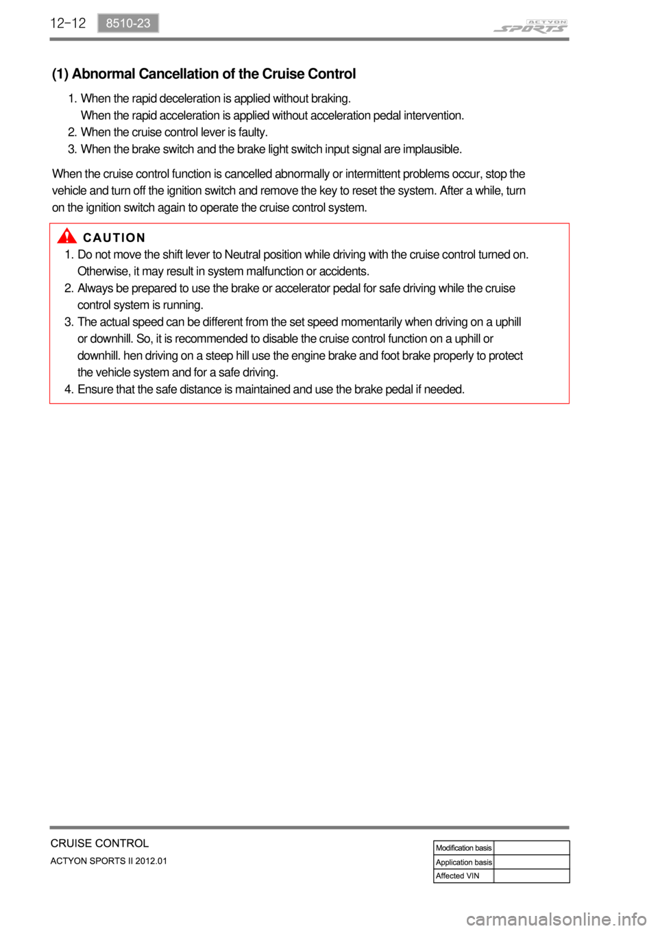
(1) Abnormal Cancellation of the Cruise Control
When the rapid deceleration is applied without braking.
When the rapid acceleration is applied without acceleration pedal intervention.
When the cruise control lever is faulty.
When the brake switch and the brake light switch input signal are implausible. 1.
2.
3.
When the cruise control function is cancelled abnormally or intermittent problems occur, stop the
vehicle and turn off the ignition switch and remove the key to reset the system. After a while, turn
on the ignition switch again to operate the cruise control system.
Page 322 of 828

15-190000-00
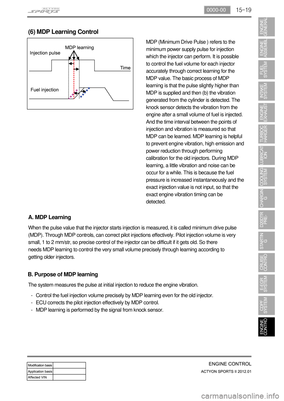
MDP (Minimum Drive Pulse ) refers to the
minimum power supply pulse for injection
which the injector can perform. It is possible
to control the fuel volume for each injector
accurately through correct learning for the
MDP value. The basic process of MDP
learning is that the pulse slightly higher than
MDP is supplied and then (b) the vibration
generated from the cylinder is detected. The
knock sensor detects the vibration from the
engine after a small volume of fuel is injected.
And the time interval between the points of
injection and vibration is measured so that
MDP can be learned. MDP learning is helpful
to prevent engine vibration, high emission and
power reduction through performing
calibration for the old injectors. During MDP
learning, a little vibration and noise can be
occur for a while. This is because the fuel
pressure is increased instantaneously and the
exact injection value is not input, so that the
exact engine vibration timing can be
detected.
(6) MDP Learning Control
A. MDP Learning
When the pulse value that the injector starts injection is measured, it is called minimum drive pulse
(MDP). Through MDP controls, can correct pilot injections effectively. Pilot injection volume is very
small, 1 to 2 mm/str, so precise control of the injector can be difficult if it gets old. So there
needs MDP learning to control the very small volume precisely through learning according to
getting older injectors.
Control the fuel injection volume precisely by MDP learning even for the old injector.
ECU corrects the pilot injection effectively by MDP control.
MDP learning is performed by the signal from knock sensor. -
-
- The system measures the pulse at initial injection to reduce the engine vibration.
B. Purpose of MDP learning
Page 329 of 828

15-26
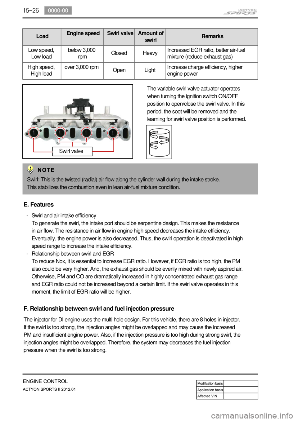
LoadEngine speed Swirl valveAmount of
swirlRemarks
Low speed,
Low loadbelow 3,000
rpmClosed HeavyIncreased EGR ratio, better air-fuel
mixture (reduce exhaust gas)
High speed,
High loadover 3,000 rpm
Open LightIncrease charge efficiency, higher
engine power
The variable swirl valve actuator operates
when turning the ignition switch ON/OFF
position to open/close the swirl valve. In this
period, the soot will be removed and the
learning for swirl valve position is performed.
Swirl: This is the twisted (radial) air flow along the cylinder wall during the intake stroke.
This stabilizes the combustion even in lean air-fuel mixture condition.
Swirl valve
E. Features
Swirl and air intake efficiency
To generate the swirl, the intake port should be serpentine design. This makes the resistance
in air flow. The resistance in air flow in engine high speed decreases the intake efficiency.
Eventually, the engine power is also decreased, Thus, the swirl operation is deactivated in high
speed range to increase the intake efficiency.
Relationship between swirl and EGR
To reduce Nox, it is essential to increase EGR ratio. However, if EGR ratio is too high, the PM
also could be very higher. And, the exhaust gas should be evenly mixed with newly aspired air.
Otherwise, PM and CO are dramatically increased in highly concentrated exhaust gas range
and EGR ratio could not be increased beyond a certain limit. If the swirl valve operates in this
moment, the limit of EGR ratio will be higher. -
-
F. Relationship between swirl and fuel injection pressure
The injector for DI engine uses the multi hole design. For this vehicle, there are 8 holes in injector.
If the swirl is too strong, the injection angles might be overlapped and may cause the increased
PM and insufficient engine power. Also, if the injection pressure is too high during strong swirl, the
injection angles might be overlapped. Therefore, the system may decreases the fuel injection
pressure when the swirl is too strong.
Page 359 of 828

01-91113-01
4. DIAGNOSTIC INFORMATION AND PROCEDURE
1) Oil Leak Diagnosis
Most fluid oil leaks are easily located and repaired by visually finding the leak and replacing or
repairing the necessary parts. On some occasions a fluid leak may be difficult to locate or repair.
The following procedures may help you in locating and repairing most leaks.
Finding the Leak ▶
Identify the fluid. Determine whether it is engine oil, automatic transmission fluid, power
steering fluid, etc.
Identify where the fluid is leaking from. -
-
After running the vehicle at normal operating temperature, park the vehicle over a large
sheet of paper.
Wait a few minutes.
You should be able to find the approximate location of the leak by the drippings on the
paper. ·
·
·
Visually check around the suspected component.
Check around all the gasket mating surfaces for leaks. A mirror is useful for finding leaks
in areas that are hard to reach.
If the leak still cannot be found, it may be necessary to clean the suspected area with a
degreaser, steam or spray solvent. -
-
Clean the area well.
Dry the area.
Operate the vehicle for several miles at normal operating temperature and varying
speeds.
After operating the vehicle, visually check the suspected component.
If you still cannot locate the leak, try using the powder or black light and dye method. ·
·
·
·
·
Clean the suspected area.
Apply an aerosol-type powder (such as foot powder) to the suspected area.
Operate the vehicle under normal operating conditoins.
Visually inspect the suspected component. You should be able to trace the leak path over
the white powder surface to the source. -
-
-
- Powder Method ▶
Page 360 of 828

01-10
Black Light and Dye Method ▶
A dye and light kit is available for finding leaks, Refer to the manufacturer's directions when using
the kit.
Pour the specified amount of dye into the engine oil fill tube.
Operate the vehicle normal operating conditions as directed in the kit.
Direct the light toward the suspected area. The dyed fluid will appear as a yellow path
leading to the source. -
-
-
Once the origin of the leak has been pinpointed and traced back to its source, the cause of the
leak must be determined in order for it to be repaired properly.
If a gasket is replaced, but the sealing flange is bent, the new gasket will not repair the leak. The
bent flange must be repaired also. Before attempting to repair a leak, check for the following
conditions and correct them as they may cause a leak.Repairing the Leak ▶
Gaskets ▶
The fluid level/pressure is too high.
The crankcase ventilation system is malfunctioning.
The seal bore is damaged (scratched, burred or nicked).
The seal is damaged or worn.
Improper installation is evident.
There are cracks in the components.
The shaft surface is scratched, nicked or damaged.
A loose or worn bearing is causing excess seal wear. -
-
-
-
-
-
-
-
Page 376 of 828

03-4
1. DESCRIPTION AND OPERATION
1) Exhaust System
When you are inspecting or replacing exhaust system components, make sure there is adequate
clearance from all points on the underbody to avoid possible
overheating of the floor panel and possible damage to the passenger compartment insulation
and trim materials.
Check the complete exhaust system and the nearby body areas and trunk lid for broken,
damaged, missing or mispositioned parts, open seams, holes, loose connections, or other
deterioration which could permit exhaust fumes to seep into the trunk may be an indication of a
problem in one of these areas. Any defects should be corrected immediately.
2) Catalytic Converter (Gasoline Engine)
When jacking or lifting the vehicle from the body side rails, be certain that the lift pads do not
contact the catalytic converter, as this could damage the catalytic converter.
Use of anything other than unleaded fuel will damage the catalyst in the catalytic converter. 1.
2.
Catalytic Converter Structure ▶
The Catalytic converter of monolith type consists
of 2 walled metal bodies which is made of
Cordierite. The principal element of converter
consists of the materials like Alumina or oxidized
Serume in order to apply to Ceramic Monolith.
Washer coat operates first, and catalytic metal
elements (Pt, Pd, Rh) operates to washer coat
next.
Monolith type is lighter than other types, easy to
manufacture and quickly approaches to proper
temperature. Washer coat is used to make a
contact surface with exhaust gas bigger by
adhering closely to small holes
of inner layer. If a lead compound or phosphorus
adheres to the surface and the temperature rises,
its surface is decreased. The total area of general
monolith converter is about 45, 000~500,000ft3.
(10 times of a football field) Generally
Alumina
(AL2 O3) is used as a raw materialand its 7
phases of gamma, delta, theta have big areas and
high stability for the temperature, and nowadays
gamma Alumina is used usually.