Page 169 of 233

Gross Vehicle Weight Rating(GVWR)
Gross Axle Weight Rating (GAWR) front
Gross Axle Weight Rating (GAWR) rear
Vehicle Identification Number (VIN)
Type of Vehicle
Month Day and Hour of Manufac- ture (MDH)
The bar code allows a computer scan-
ner to read the Vehicle Identification
Number (VIN).
GROSS VEHICLE WEIGHT
RATING (GVWR)
The GVWR is the total allowable
weight of your vehicle. This includes
driver, passengers, and cargo. The to-
tal load must be limited so that you do
not exceed the GVWR.
GROSS AXLE WEIGHT
RATING (GAWR)
The GAWR is the maximum capacity
of the front and rear axles. Distribute
the load over the front and rear axles evenly. Make sure that you do not
exceed either front or rear GAWR.
WARNING!
Because the front wheels steer the
vehicle, it is important that you do
not exceed the maximum front or
rear GAWR. A dangerous driving
condition can result if either rating is
exceeded. You could lose control of
the vehicle and have a collision.
OVERLOADING
The load carrying components (axle,
springs, tires, wheels, etc.) of your
vehicle will provide satisfactory ser-
vice as long as you do not exceed the
GVWR and front and rear GAWR.
The best way to figure out the total
weight of your vehicle is to weigh it
when it is fully loaded and ready for
operation. Weigh it on a commercial
scale to ensure that it is not over the
GVWR.
Figure out the weight on the front and
rear of the vehicle separately. It is
important that you distribute the load
evenly over the front and rear axles. Overloading can cause potential
safety hazards and shorten useful ser-
vice life. Heavier axles or suspension
components do not necessarily in-
crease the
vehicle's GVWR.
LOADING
To load your vehicle properly, first
figure out its empty weight, axle by
axle and side by side. Store heavier
items down low and be sure you dis-
tribute their weight as evenly as pos-
sible. Stow all loose items securely
before driving. If weighing the loaded
vehicle shows that you have exceeded
either GAWR, but the total load is
within the specified GVWR, you must
redistribute the weight. Improper
weight distribution can have an ad-
verse effect on the way your vehicle
steers and handles and the way the
brakes operate.
TRAILER TOWING
Trailer towing with this vehicle is not
recommended.
162
Page 170 of 233

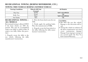
RECREATIONAL TOWING (BEHIND MOTORHOME, ETC.)
TOWING THIS VEHICLE BEHIND ANOTHER VEHICLE
Towing ConditionWheels OFF the
Ground All Models
Flat Tow NONE NOT ALLOWED
Dolly Tow Front
OK
Rear NOT ALLOWED
On Trailer ALL OK
RECREATIONAL TOWING –
ALL MODELS
Recreational towing is allowed ONLY
if the front wheels are OFF the
ground. This may be accomplished
using a tow dolly or vehicle trailer. If
using a tow dolly, follow this proce-
dure:
1. Properly secure the dolly to the
tow vehicle, following the dolly
manufactur er's instructions. 2. Drive the front wheels onto the tow
dolly.
3. Firmly apply the parking brake.
Place the transmission in PARK.
4. Properly secure the front wheels to
the dolly, following the dolly
manu-
factur er's instructions.
CAUTION!
DO NOT flat tow this vehicle.
Damage to the drivetrain will r e-
sult.
Towing this vehicle in violation of
the above requirements can cause
severe transmission damage.
Damage from improper towing is
not covered under the New Ve-
hicle Limited Warranty.
163
Page 171 of 233
Page 172 of 233
6
WHAT TO DO IN EMERGENCIES
HAZARD WARNING FLASHERS . . . . . . . . . . . . 166
IF YOUR ENGINE OVERHEATS . . . . . . . . . . . . . 166 ENGINE OIL OVERHEATING . . . . . . . . . . . . . 167
TIREFIT KIT . . . . . . . . . . . . . . . . . . . . . . . . . . . 167 TIREFIT STORAGE . . . . . . . . . . . . . . . . . . . . 167
TIREFIT KIT COMPONENTS ANDOPERATION . . . . . . . . . . . . . . . . . . . . . . . . . 167
TIREFIT USAGE PRECAUTIONS . . . . . . . . . . 168
SEALING A TIRE WITH TIREFIT . . . . . . . . . 169
JUMP-STARTING . . . . . . . . . . . . . . . . . . . . . . . . 172 PREPARATIONS FOR JUMP-START . . . . . . . 173
JUMP-STARTING PROCEDURE . . . . . . . . . . . 173
FREEING A STUCK VEHICLE . . . . . . . . . . . . . . 174
SHIFT LEVER OVERRIDE . . . . . . . . . . . . . . . . . 175
TOWING A DISABLED VEHICLE . . . . . . . . . . . 176 AUTOMATIC TRANSMISSION . . . . . . . . . . . . 176
WITHOUT THE IGNITION KEY . . . . . . . . . . . 177
165
Page 173 of 233

HAZARD WARNING
FLASHERS
The Hazard Warning flasher switch is
located on the instrument panel, be-
low the radio.Press the switch to turn on the
Hazard Warning flasher. When
the switch is activated, all di-
rectional turn signals will flash on and
off to warn oncoming traffic of an
emergency. Press the switch a second
time to turn off the Hazard Warning
flashers.
This is an emergency warning system
and it should not be used when the
vehicle is in motion. Use it when your
vehicle is disabled and it is creating a
safety hazard for other motorists.
When you must leave the vehicle to
seek assistance, the Hazard Warning
flashers will continue to operate even
though the ignition is placed in the
OFF position.
NOTE:
With extended use the Hazard
Warning flashers may wear down
your battery. IF YOUR ENGINE
OVERHEATS
In any of the following situations, you
can reduce the potential for overheat-
ing by taking the appropriate action.
On the highways — Slow down.
In city traffic — While stopped, put
transaxle in NEUTRAL, but do not
increase engine idle speed.
CAUTION!
Driving with a hot cooling system
could damage your vehicle. If tem-
perature gauge reads “H”, pull over
and stop the vehicle with the engine
at idle, when safe. Turn the air con-
ditioner off and wait until the
pointer drops back into the normal
range. After appropriate action has
been taken, if the pointer remains on
the “H”, turn the engine off imme-
diately, and call for service.
NOTE:
There are steps that you can take to
slow down an impending overheat
condition: If your air conditioner (A/C) is
on, turn it off. The A/C system
adds heat to the engine cooling
system and turning the A/C off
can help remove this heat.
You can also turn the tempera- ture control to maximum heat,
the mode control to floor and the
blower control to high. This al-
lows the heater core to act as a
supplement to the radiator and
aids in removing heat from the
engine cooling system.
WARNING!
You or others can be badly burned
by hot engine coolant (antifreeze) or
steam from your radiator. If you see
or hear steam coming from under
the hood, do not open the hood until
the radiator has had time to cool.
Never try to open a cooling system
pressure cap when the radiator or
coolant bottle is hot.
166
Page 174 of 233

ENGINE OIL
OVERHEATING
During sustained high-speed driving
or trailer tow up long grades on a hot
day, the engine oil temperature may
become too hot. If this happens, the
“HOTOIL” message flashes in the
odometer and the vehicle speed will
be reduced to 85 km/h until the en-
gine oil temperature is reduced.
NOTE:
The vehicle speed is reduced to a
maximum of 85 km/h. You may of
course, reduce your vehicle speed
further if needed.
TIREFIT KIT
Small punctures up to 6 mm in the tire
tread can be sealed with TIREFIT.
Foreign objects (e.g., screws or nails)
should not be removed from the tire.
TIREFIT can be used in outside tem-
peratures down to approximately
20°C.
This kit will provide a temporary tire
seal, allowing you to drive your ve-
hicle up to 160 km with a maximum
speed of 88 km/h.TIREFIT STORAGE
The TIREFIT kit is located in the
trunk.
TIREFIT KIT
COMPONENTS AND
OPERATION
1. Sealant Bottle
2. Deflation Button
3. Pressure Gauge
4. Power Button5. Mode Select Knob
6. Sealant Hose (Clear)
7. Air Pump Hose (Black)
8. Power Plug
Using The Mode Select Knob And
Hoses
Your TIREFIT kit is equipped with
the following symbols to indicate the
air or sealant mode.
Selecting Air Mode
Turn the Mode Select Knob
(5) to this position for air
pump operation only. Use
the Black Air Pump Hose
(7) when selecting this mode.
Selecting Sealant Mode Turn the Mode Se-
lect Knob (5) to
this position to in-
ject the TIREFIT
Sealant and to in-
flate the tire. Use
the Sealant Hose
(clear hose) (6) when selecting this
mode.
TIREFIT Location
167
Page 175 of 233

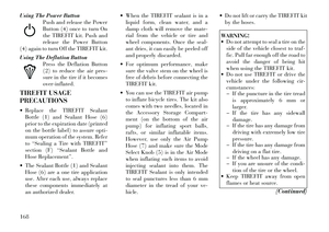
Using The Power ButtonPush and release the Power
Button (4) once to turn On
the TIREFIT kit. Push and
release the Power Button
(4) again to turn Off the TIREFIT kit.
Using The Deflation Button Press the Deflation Button
(2) to reduce the air pres-
sure in the tire if it becomes
over-inflated.
TIREFIT USAGE
PRECAUTIONS
Replace the TIREFIT Sealant Bottle (1) and Sealant Hose (6)
prior to the expiration date (printed
on the bottle label) to assure opti-
mum operation of the system. Refer
to “Sealing a Tire with TIREFIT”
section (F) “Sealant Bottle and
Hose Replacement”.
The Sealant Bottle (1) and Sealant Hose (6) are a one tire application
use. After each use, always replace
these components immediately at
an authorized dealer. When the TIREFIT sealant is in a
liquid form, clean water, and a
damp cloth will remove the mate-
rial from the vehicle or tire and
wheel components. Once the seal-
ant dries, it can easily be peeled off
and properly discarded.
For optimum performance, make sure the valve stem on the wheel is
free of debris before connecting the
TIREFIT kit.
You can use the TIREFIT air pump to inflate bicycle tires. The kit also
comes with two needles, located in
the Accessory Storage Compart-
ment (on the bottom of the air
pump) for inflating sport balls,
rafts, or similar inflatable items.
However, use only the Air Pump
Hose (7) and make sure the Mode
Select Knob (5) is in the Air Mode
when inflating such items to avoid
injecting sealant into them. The
TIREFIT Sealant is only intended
to seal punctures less than 6 mm
diameter in the tread of your ve-
hicle. Do not lift or carry the TIREFIT kit
by the hoses.
WARNING!
Do not attempt to seal a tire on the
side of the vehicle closest to traf-
fic. Pull far enough off the road to
avoid the danger of being hit
when using the TIREFIT kit.
Do not use TIREFIT or drive the
vehicle under the following cir-
cumstances:
If the puncture in the tire tread is approximately 6 mm or
larger.
If the tire has any sidewall
damage.
If the tire has any damage from
driving with extremely low tire
pressure.
If the tire has any damage from
driving on a flat tire.
If the wheel has any damage.
If you are unsure of the condi-
tion of the tire or the wheel.
Keep TIREFIT away from open
flames or heat source.
(Continued)
168
Page 176 of 233

WARNING!(Continued)
A loose TIREFIT kit thrown for-
ward in a collision or hard stop
could endanger the occupants of
the vehicle. Always stow the
TIREFIT kit in the place pro-
vided. Failure to follow these
warnings can result in injuries
that are serious or fatal to you,
your passengers, and others
around you.
Take care not to allow the con-
tents of TIREFIT to come in con-
tact with hair, eyes, or clothing.
TIREFIT is harmful if inhaled,
swallowed, or absorbed through
the skin. It causes skin, eye, and
respiratory irritation. Flush im-
mediately with plenty of water if
there is any contact with eyes or
skin. Change clothing as soon as
possible, if there is any contact
with clothing.
(Continued)
WARNING!(Continued)
TIREFIT Sealant solution con-
tains latex. In case of an allergic
reaction or rash, consult a physi-
cian immediately. Keep TIREFIT
out of reach of children. If swal-
lowed, rinse mouth immediately
with plenty of water and drink
plenty of water. Do not induce
vomiting! Consult a physician im-
mediately.
SEALING A TIRE WITH
TIREFIT
(A) Whenever You Stop To Use
TIREFIT:
1. Pull over to a safe location and
turn on the vehicle’s Hazard Warning
flashers.
2. Verify that the valve stem (on the
wheel with the deflated tire) is in a
position that is near to the ground.
This will allow the TIREFIT Hoses
(6) and (7) to reach the valve stem
and keep the TIREFIT kit flat on the
ground. This will provide the best po-
sitioning of the kit when injecting the
sealant into the deflated tire and run- ning the air pump. Move the vehicle as
necessary to place the valve stem in
this position before proceeding.
3. Place the transmission in PARK
(auto transmission) or in Gear
(manual transmission) and turn Off
the ignition.
4. Set the parking brake.
(B) Setting Up To Use TIREFIT:
1. Turn the Mode Select Knob (5) to
the Sealant Mode position.
2. Uncoil the Sealant Hose (6) and
then remove the cap from the fitting
at the end of the hose.
3. Place the TIREFIT kit flat on the
ground next to the deflated tire.
4. Remove the cap from the valve
stem and then screw the fitting at the
end of the Sealant Hose (6) onto the
valve stem.
5. Uncoil the Power Plug (8) and in-
sert the plug into the vehicle’s 12 Volt
power outlet.
NOTE:
Do not remove foreign objects (e.g.,
screws or nails) from the tire.
169