Page 177 of 233
 (C) Injecting TIREFIT Sealant
Into The Deflated Tire:
Always start the engine beforeturning ON the TIREFIT kit.
NOTE:
Manual transmission vehicles
must have the parking brake en-
gaged and the shift")
(C) Injecting TIREFIT Sealant
Into The Deflated Tire:
Always start the engine beforeturning ON the TIREFIT kit.
NOTE:
Manual transmission vehicles
must have the parking brake en-
gaged and the shift lever in NEU-
TRAL.
After pressing the Power Button (4), the sealant (white fluid) will
flow from the Sealant Bottle (1)
through the Sealant Hose (6) and
into the tire.
NOTE:
Sealant may leak out through the
puncture in the tire.
If the sealant (white fluid) does not
flow within 0 – 10 seconds through
the Sealant Hose (6):
1. Press the Power Button (4) to turn
Off the TIREFIT kit. Disconnect the
Sealant Hose (6) from the valve stem.
Make sure the valve stem is free of
debris. Reconnect the Sealant Hose
(6) to the valve stem. Check that the
Mode Select Knob (5) is in the Sealant Mode position and not Air Mode.
Press the Power Button (4) to turn On
the TIREFIT kit.
2. Connect the Power Plug (8) to a
different 12 Volt power outlet in your
vehicle or another vehicle, if avail-
able. Make sure the engine is running
before turning ON the TIREFIT kit.
3. The Sealant Bottle (1) may be
empty due to previous use. Call for
assistance.
NOTE:
If the Mode Select Knob (5) is on
Air Mode and the pump is operat-
ing, air will dispense from the Air
Pump Hose (7) only, not the Seal-
ant Hose (6).
If the sealant (white fluid) does
flow
through the Sealant Hose (6):
1. Continue to operate the pump un-
til sealant is no longer flowing
through hose (typically takes 30 -
70 seconds). As the sealant flows
through the Sealant Hose (6), the
Pressure Gauge (3) can read as high
as 5 Bar. The Pressure Gauge (3) will
decrease quickly from approximately 70 psi (5 Bar) to the actual tire pres-
sure when the Sealant Bottle (1) is
empty.
2. The pump will start to inject air
into the tire immediately after the
Sealant Bottle (1) is empty. Continue
to operate the pump and inflate the
tire to the pressure indicated on the
tire pressure label on the driver-side
latch pillar (recommended pressure).
Check the tire pressure by looking at
the Pressure Gauge (3).
If the tire does not inflate to at least
1.8 Bar pressure within 15 min-
utes:
The tire is too badly damaged. Do
not attempt to drive the vehicle fur-
ther. Call for assistance.
NOTE:
If the tire becomes over-inflated,
press the Deflation Button to re-
duce the tire pressure to the rec-
ommended inflation pressure be-
fore continuing.
If the tire inflates to the recom-
mended pressure or is at least 1.8
Bar pressure within 15 minutes:
170
Page 178 of 233
 1. Press the Power Button (4) to turn
off the TIREFIT kit.
2. Remove the Speed Limit sticker
from the top of the Sealant Bottle (1)
and place the sticker on the instru-
ment panel.
3. Immediately disc")
1. Press the Power Button (4) to turn
off the TIREFIT kit.
2. Remove the Speed Limit sticker
from the top of the Sealant Bottle (1)
and place the sticker on the instru-
ment panel.
3. Immediately disconnect the Seal-
ant Hose (6) from the valve stem,
reinstall the cap on the fitting at the
end of the hose, and place the TIRE-
FIT kit in the vehicle storage location.
Quickly proceed to (D) “Drive Ve-
hicle”.CAUTION!
The metal end fitting from PowerPlug (8) may get hot after use, so
it should be handled carefully.
Failure to reinstall the cap on the
fitting at the end of the Sealant
Hose (6) can result in sealant con-
tacting your skin, clothing, and
the vehicle’s interior. It can also
result in sealant contacting inter-
nal TIREFIT kit components
which may cause permanent
damage to the kit. (D) Drive Vehicle:
Immediately after injecting sealant
and inflating the tire, drive the vehicle
8 km or 10 minutes to ensure distri-
bution of the TIREFIT Sealant within
the tire. Do not exceed 88 km/h.
WARNING!
TIREFIT is not a permanent flat tire
repair. Have the tire inspected and
repaired or replaced after using
TIREFIT. Do not exceed 88 km/h
until the tire is repaired or replaced.
Failure to follow this warning can
result in injuries that are serious or
fatal to you, your passengers, and
others around you.
(E) After Driving:
Pull over to a safe location. Refer to
“Whenever You Stop to Use TIRE-
FIT” before continuing.
1. Turn the Mode Select Knob (5) to
the Air Mode position.
2. Uncoil the power plug and insert
the plug into the vehicle's 12 Volt
power outlet. 3. Uncoil the Air Pump Hose (7)
(black in color) and screw the fitting
at the end of hose (7) onto the valve
stem.
4. Check the pressure in the tire by
reading the Pressure Gauge (3).
If tire pressure is less than 1.3 Bar,
the tire is too badly damaged. Do not
attempt to drive the vehicle further.
Call for assistance.
If the tire pressure is 1.3 Bar or
higher:
1. Press the Power Button (4) to turn
on TIREFIT and inflate the tire to the
pressure indicated on the tire and
loading information label on the
driver
-side door opening.
NOTE:
If the tire becomes over-inflated,
press the Deflation Button to re-
duce the tire pressure to the rec-
ommended inflation pressure be-
fore continuing.
2. Disconnect the TIREFIT kit from
the valve stem, reinstall the cap on the
valve stem and unplug from 12 Volt
outlet.
171
Page 179 of 233
 3. Place the TIREFIT kit in its proper
storage area in the vehicle.
4. Have the tire inspected and re-
paired or replaced at the earliest op-
portunity at an authorized dealer or
tire service center.")
3. Place the TIREFIT kit in its proper
storage area in the vehicle.
4. Have the tire inspected and re-
paired or replaced at the earliest op-
portunity at an authorized dealer or
tire service center.
5. Replace the Sealant Bottle (1) and
Sealant Hose (6) assembly at your
authorized dealer as soon as possible.
Refer to “(F) Sealant Bottle and Hose
Replacement.”
NOTE:
When having the tire serviced, ad-
vise the authorized dealer or ser-
vice center that the tire has been
sealed using the TIREFIT service
kit.
(F) Sealant Bottle And Hose
Replacement:
1. Uncoil the Sealant Hose (6) (clear
in color).
2. Locate the round Sealant Bottle
release button in the recessed area
under the sealant bottle.3. Press the Sealant Bottle release
button. The Sealant Bottle (1) will
pop up. Remove the bottle and dis-
pose of it accordingly.
4. Clean any remaining sealant from
the TIREFIT housing.
5. Position the new Sealant Bottle (1)
in the housing so that the Sealant
Hose (6) aligns with the hose slot in
the front of the housing. Press the
bottle into the housing. An audible
click will be heard indicating the
bottle is locked into place.
6. Verify that the cap is installed on
the fitting at the end of the Sealant
Hose (6) and return the hose to its
storage area (located on the bottom of
the air pump).
7. Return the TIREFIT kit to its stor-
age location in the vehicle.
JUMP-STARTING
If your vehicle has a discharged bat-
tery it can be jump-started using a set
of jumper cables and a battery in an-
other vehicle or by using a portable
battery booster pack. Jump-starting
can be dangerous if done improperly
so please follow the procedures in this
section carefully.
NOTE:
When using a portable battery
booster pack follow the manufac-
turer's operating instructions and
precautions.
CAUTION!
Do not use a portable battery
booster pack or any other booster
source with a system voltage greater
than 12 Volts or damage to the bat-
tery, starter motor, alternator or
electrical system may occur.WARNING!
Do not attempt jump-starting if the
battery is frozen. It could rupture or
explode and cause personal injury.
172
Page 180 of 233
 PREPARATIONS FOR
JUMP-START
The battery in your vehicle is located
between the left front headlight as-
sembly and the left front wheel splash
shield. To allow jump-starting there
are remote battery p")
PREPARATIONS FOR
JUMP-START
The battery in your vehicle is located
between the left front headlight as-
sembly and the left front wheel splash
shield. To allow jump-starting there
are remote battery posts located on
the left side of the engine compart-
ment.WARNING!
Take care to avoid the radiatorcooling fan whenever the hood is
raised. It can start anytime the
ignition switch is on. You can be
injured by moving fan blades.
(Continued)
WARNING!(Continued)
Remove any metal jewelry such as
watch bands or bracelets that
might make an inadvertent elec-
trical contact. You could be seri-
ously injured.
Batteries contain sulfuric acid
that can burn your skin or eyes
and generate hydrogen gas which
is flammable and explosive. Keep
open flames or sparks away from
the battery.
1. Set the parking brake, shift the
automatic transmission into PARK
and turn the ignition to LOCK.
2. Turn off the heater, radio, and all
unnecessary electrical accessories.
3. Remove the protective cover over
the remote positive (+)battery post.
To remove the cover, press the locking
tab and pull upward on the cover. 4. If using another vehicle to jump-
start the battery, park the vehicle
within the jumper cables reach, set
the parking brake and make sure the
ignition is OFF.
WARNING!
Do not allow vehicles to touch each
other as this could establish a
ground connection and personal in-
jury could result.
JUMP-STARTING
PROCEDUREWARNING!
Failure to follow this procedure
could result in personal injury or
property damage due to battery ex-
plosion.
Remote Battery Posts
1 — Remote Positive (+) Post (cov-
ered with protective cap)
2 — Remote Negative (-) Post
Locking Tab
173
Page 181 of 233
 CAUTION!
Failure to follow these procedures
could result in damage to the charg-
ing system of the booster vehicle or
the discharged vehicle.
1. Connect the positive (+)end of the
jumper cable to the")
CAUTION!
Failure to follow these procedures
could result in damage to the charg-
ing system of the booster vehicle or
the discharged vehicle.
1. Connect the positive (+)end of the
jumper cable to the remote positive
(+) post of the discharged vehicle.
2. Connect the opposite end of the
positive (+)jumper cable to the posi-
tive (+)post of the booster battery.
3. Connect the negative end (-)of the
jumper cable to the negative (-)post
of the booster battery.
4. Connect the opposite end of the
negative (-)jumper cable to the re-
mote negative (-)post of the vehicle
with the discharged battery.WARNING!
Do not connect the cable to the nega-
tive post (-)of the discharged bat-
tery. The resulting electrical spark
could cause the battery to explode
and could result in personal injury.
5. Start the engine in the vehicle that
has the booster battery, let the engine idle a few minutes, and then start the
engine in the vehicle with the dis-
charged battery.
Once the engine is started, remove the
jumper cables in the reverse sequence:
6. Disconnect the negative
(-)jumper
cable from the remote negative (-)
post of the vehicle with the discharged
battery.
7. Disconnect the negative end (-)of
the jumper cable from the negative (-)
post of the booster battery.
8. Disconnect the opposite end of the
positive (+)jumper cable from the
positive (+)post of the booster bat-
tery.
9. Disconnect the positive (+)end of
the jumper cable from the remote
positive (+)post of the discharged ve-
hicle.
10. Reinstall the protective cover
over the remote positive (+)battery
post of the discharged vehicle.
If frequent jump-starting is required
to start your vehicle you should have
the battery and charging system in-
spected at your authorized dealer.
CAUTION!
Accessories that can be plugged into
the vehicle power outlets draw
power from the vehicle’s battery,
even when not in use (i.e., cellular
phones, etc.). Eventually, if plugged
in long enough, the vehicle’s battery
will discharge sufficiently to degrade
battery life and/or prevent the en-
gine from starting.
FREEING A STUCK
VEHICLE
If your vehicle becomes stuck in mud,
sand, or snow, it can often be moved
by a rocking motion. Turn your steer-
ing wheel right and left to clear the
area around the front wheels. Then
shift back and forth between DRIVE
and REVERSE. Using minimal accel-
erator pedal pressure to maintain the
rocking motion, without spinning the
wheels, is most effective.
174
Page 182 of 233
 CAUTION!
Racing the engine or spinning the
wheels may lead to transmission
overheating and failure. Allow the
engine to idle with the shift lever in
NEUTRAL for at least one minute
after every five ro")
CAUTION!
Racing the engine or spinning the
wheels may lead to transmission
overheating and failure. Allow the
engine to idle with the shift lever in
NEUTRAL for at least one minute
after every five rocking-motion
cycles. This will minimize overheat-
ing and reduce the risk of transmis-
sion failure during prolonged efforts
to free a stuck vehicle.
NOTE:
If your vehicle is equipped with
Electronic Stability Control (ESC),
turn the system to Partial OFF be-
fore attempting to “rock” the ve-
hicle. Refer to “Electronic Brake
Control” in “Starting And Operat-
ing” for further information.CAUTION!
When “rocking” a stuck vehicle by moving between DRIVE and
REVERSE, do not spin the wheels
faster than 24 km/h, or drivetrain
damage may result.
(Continued)
CAUTION!(Continued)
Revving the engine or spinning
the wheels too fast may lead to
transmission overheating and
failure. It can also damage the
tires. Do not spin the wheels above
48 km/h while in gear (no trans-
mission shifting occurring).WARNING!
Fast spinning tires can be danger-
ous. Forces generated by excessive
wheel speeds may cause damage, or
even failure, of the axle and tires. A
tire could explode and injure some-
one. Do not spin your vehicle's
wheels faster than 48 km/h or for
longer than 30 seconds continuously
without stopping when you are stuck
and do not let anyone near a spin-
ning wheel, no matter what the
speed.
SHIFT LEVER
OVERRIDE
If a malfunction occurs and the shift
lever cannot be moved out of the
PARK position, you can use the fol- lowing procedure to temporarily
move the shift lever:
1. Firmly apply the parking brake.
2. Remove the cupholder liner.
3. Turn the ignition to the ON/RUN
position without starting the engine.
4. Press and maintain firm pressure
on the brake pedal.
5. Insert a screwdriver or similar tool
into the hole at the front of the cup-
holder and push and hold the override
lever forward.
6. Move the shift lever into the NEU-
TRAL position.
7. The vehicle may then be started in
NEUTRAL.
8. Reinstall the cupholder liner.
Shift Lever Override
175
Page 183 of 233
 TOWING A DISABLED VEHICLE
Towing ConditionWheels OFF the Ground Automatic Transmissions
Flat Tow NONEIf transmission is operable:
Transmission inNEUTRAL
40 km/hmax speed
24 km maxdistance
Wheel")
TOWING A DISABLED VEHICLE
Towing ConditionWheels OFF the Ground Automatic Transmissions
Flat Tow NONEIf transmission is operable:
Transmission inNEUTRAL
40 km/hmax speed
24 km maxdistance
Wheel Lift Or Dolly Tow Rear
Front OK
Flatbed ALLBEST METHOD
Proper towing or lifting equipment is
required to prevent damage to your
vehicle. Use only tow bars and other
equipment designed for the purpose,
following equipment manufacturer’s
instructions. Use of safety chains is
mandatory. Attach a tow bar or other
towing device to main structural
members of the vehicle, not to bum-
pers or associated brackets. State and
local laws applying to vehicles under
tow must be observed.
If you must use the accessories (wip-
ers, defrosters, etc.) while being
towed, the ignition must be in the
ON/RUN position, not the ACC posi-
tion.
CAUTION!
Do not use sling type equipment when towing. Damage to the fas-
cia will occur.
When securing the vehicle to a
flatbed truck, do not attach to
front or rear suspension compo-
nents. Damage to your vehicle
may result from improper towing.
Do not push or tow this vehicle
with another vehicle as damage to
the bumper fascia and transmis-
sion may result.
If the vehicle being towed requires
steering, the ignition switch must
be in the ON position, not the
LOCK or ACC positions. AUTOMATIC
TRANSMISSION
The manufacturer recommends tow-
ing your vehicle with all four wheels
OFF the ground using a flatbed.
If flatbed equipment is not available,
and the transmission is operable, the
vehicle may be flat towed (with all
four wheels on the ground) under the
following conditions:
The shift lever must be in NEU-
TRAL.
The towing distance must not ex- ceed 24 km.
The towing speed must not exceed 40 km/h.
176
Page 184 of 233
 If the transmission is not operable,
or the vehicle must be towed faster
than 40 km/h or farther than
24 km, it must be towed with the
front wheels OFF the ground (us-
ing a flatbed truck, towing doll")
If the transmission is not operable,
or the vehicle must be towed faster
than 40 km/h or farther than
24 km, it must be towed with the
front wheels OFF the ground (us-
ing a flatbed truck, towing dolly, or
wheel lift equipment with the front
wheels raised).CAUTION!
Towing faster than 40 km/h or far-
ther than 24 km with front wheels
on the ground can cause severe dam-
age to the transmission. Such dam-
age is not covered by the New Ve-
hicle Limited Warranty.WITHOUT THE IGNITION
KEY
Special care must be taken when the
vehicle is towed with the ignition in
the LOCK position. Flatbed towing is
the preferred towing method. How-
ever, if a flatbed towing vehicle is not
available, wheel lift towing equip-
ment may be used. Rear towing (with
the front wheels on the ground) is not
allowed, as transmission damage will
occur. If rear towing is the only alter-
native, the front wheels must be
placed on a towing dolly. Proper tow-
ing equipment is necessary to prevent
damage to the vehicle.
CAUTION!
Failure to follow these towing meth-
ods can cause severe damage to the
transmission. Such damage is not
covered by the New Vehicle Limited
Warranty.
177
 1
1 2
2 3
3 4
4 5
5 6
6 7
7 8
8 9
9 10
10 11
11 12
12 13
13 14
14 15
15 16
16 17
17 18
18 19
19 20
20 21
21 22
22 23
23 24
24 25
25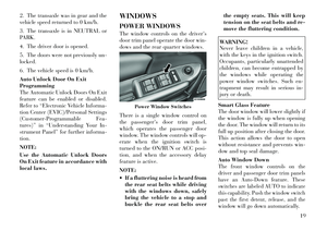 26
26 27
27 28
28 29
29 30
30 31
31 32
32 33
33 34
34 35
35 36
36 37
37 38
38 39
39 40
40 41
41 42
42 43
43 44
44 45
45 46
46 47
47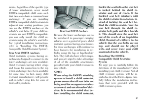 48
48 49
49 50
50 51
51 52
52 53
53 54
54 55
55 56
56 57
57 58
58 59
59 60
60 61
61 62
62 63
63 64
64 65
65 66
66 67
67 68
68 69
69 70
70 71
71 72
72 73
73 74
74 75
75 76
76 77
77 78
78 79
79 80
80 81
81 82
82 83
83 84
84 85
85 86
86 87
87 88
88 89
89 90
90 91
91 92
92 93
93 94
94 95
95 96
96 97
97 98
98 99
99 100
100 101
101 102
102 103
103 104
104 105
105 106
106 107
107 108
108 109
109 110
110 111
111 112
112 113
113 114
114 115
115 116
116 117
117 118
118 119
119 120
120 121
121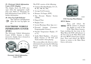 122
122 123
123 124
124 125
125 126
126 127
127 128
128 129
129 130
130 131
131 132
132 133
133 134
134 135
135 136
136 137
137 138
138 139
139 140
140 141
141 142
142 143
143 144
144 145
145 146
146 147
147 148
148 149
149 150
150 151
151 152
152 153
153 154
154 155
155 156
156 157
157 158
158 159
159 160
160 161
161 162
162 163
163 164
164 165
165 166
166 167
167 168
168 169
169 170
170 171
171 172
172 173
173 174
174 175
175 176
176 177
177 178
178 179
179 180
180 181
181 182
182 183
183 184
184 185
185 186
186 187
187 188
188 189
189 190
190 191
191 192
192 193
193 194
194 195
195 196
196 197
197 198
198 199
199 200
200 201
201 202
202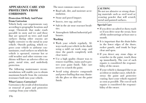 203
203 204
204 205
205 206
206 207
207 208
208 209
209 210
210 211
211 212
212 213
213 214
214 215
215 216
216 217
217 218
218 219
219 220
220 221
221 222
222 223
223 224
224 225
225 226
226 227
227 228
228 229
229 230
230 231
231 232
232