Page 25 of 316

Fue l consumption is reca lculated at interva ls
of 33 yards (30 meters). This display switches
to gallons/hour (liters/hour) when the vehicle is not moving.
Average speed
The average speed in mph (km/h) since the
l ast time the disp lay was reset appears in the
display .
Elapsed time
The length of time that you have been driving
since yo u last reset the memory appears in
this display.
Distance
The distance that has been covered since the
l ast time the memory was cleared appears in
the disp lay.
(D Tips
- Fuel consumptions (ave rage and cur
rent), range and speed are displayed in
metric units on Canadian models.
-All stored va lues w ill be lost if the veh i
cle battery is dis connected .
Memories
The trip computer is equipped with two fully
automatic memories as well as an efficiency
program".
Fig. 17 Trip computer d isplay: memo ry level 1
You can switch between the trip computer 1
and 2 and the efficiency program* by pressing
the
! RESET I button @¢ page 23, fig. 18.
You can tell which memo ry level is cur rently
active by the number or the sign in the display
Driver information display 23
¢ fig. 17. The data from the single-trip mem
ory (memory level 1) is being displayed if a
D
appears in the display . If a fJ is shown, then
the data from the total-trip memory is being
displayed (memory level 2). The fuel pump nozzle
iii indicates the efficiency program*
¢page 24.
Single-trip memory (Trip computer 1)
The single-trip memory stores the trip infor
mation from the time the ignition is turned on
until it is turned off. If the tr ip is continued
within 2 hours from the time the ignition was
turned off, the new data will be included in
the calculat ion of the current trip informa
tion. If the trip is interrupted for
more than 2
hours
the memo ry is reset automatically.
Total-trip memory (Trip computer 2)
Unlike the single -trip memory, the total -trip
memo ry is not reset automat ical ly. This per
mits you to evaluate your driv ing data for the
entire period between manua l resets.
Efficiency program*
The efficiency program can help you to use
less fuel ¢
page 24.
Operation
The trip computer is controlled by two
switches on the windshield wiper lever .
Fig. 18 Windsh ield wiper lever : contro ls for the t rip
computer
.. To display the trip computer memory levels,
press the
I RESET ! button@¢ fig. 18 re
peatedly until the desired memory level is
shown in the display . .,.
Page 26 of 316

24 Driver in formation d isplay
• To disp lay trip information within a memory
l ev el, pr ess the top or bottom part of the
function selection switch
@ .
The trip computer wi ll not operate unless the
ignition is on. When you turn on the ignition,
the function that was in us e when you last
tu rned the ignition off will be disp layed.
I n addition to information on the trip comput
er (trip computer 1 and 2 and the efficiency program*), the digital speedometer and infor
mation regarding the navigation system* can
also be displayed. To switc h the display be
tween the different information, tap the
I RES ET I button @ briefly .
Setting v alu es to ze ro
To delete on e current value from the trip com
puter, select the desired function and press
the
I R ES ET I button @for at least one second.
The follow ing values can be set to zero
indi
vi dually :
- Average fuel mileage
- Average speed
-Elapsed time
- Distance
All currently displayed values are deleted in
the efficiency program* .
In addition,
all the values in the s ingle-trip or
the total-trip memory can be deleted simulta neously ¢
page 24 .
(Di Tips
All stored values will be lost if the vehicle
battery is disconnected .
Basic Settings for the trip computer
The radio or MMI* operating unit is used for
set ting the trip computer's basic settings.
• Se lect: F unction button ICARI > Instrument
cluster
> On-boa rd compute r 1 or On- boa rd
computer 2 .
The values in the single-trip or the total-trip
memory can a ll be reset to zero at the same
time under
Reset in the menu . In addition, you can determine what
informa
tion from the trip computer should be shown in the instrument cluster d isp lay. If one of the
pieces of driver information is turned
Off , that
driver information will not be shown in the
display . The information w ill continue to be
calculated by the tr ip compute r and can be
turned back
On at any t ime .
(D Tips
The dr iving information in the efficiency
program* is also reset to zero w ith the s in
gle-tr ip memory.
Efficiency program
Description
Applies to vehicles: with trip compute r with efficiency
prog ram
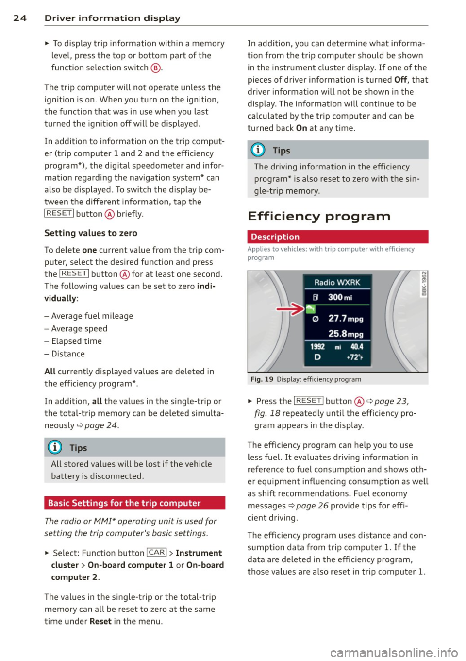
Fi g. 19 D isp lay: eff iciency prog ram
• Press the I RES ET I button @¢ page 23 ,
fig . 18
repeatedly unt il the effic iency p ro
gram appears i n the display.
The efficiency program can he lp you to use
less fuel. It evaluates d riving informat ion in
reference to fuel consumption and shows oth
er equipment influencing consumption as well
as sh ift recommendat ions . Fuel economy
messages ¢
page 26 provide tips fo r eff i
c ient driving .
T he efficiency program uses distance and con
s u mption data from t rip compu ter
1. If the
da ta are deleted in the effi cien cy program,
those values are also reset in tr ip comp uter
1.
Page 27 of 316

Enhanced shift indicator
Applies to vehicles: with manua l transmission and trip
computer with efficiency program
Fig. 20 Display: e nhan ce d shi ft ind icato r
.,.. In the eff ic iency p rogram, press the f unc
tion selection switch
r:!;> page 2 3, fig . 18 @
repeated ly until the enhanced shift indicator
appears in the display .
The eff ic iency program also has an enhanced
shift indicator . This enhanced shift indicator
follows the same concept as the "standard" shift indicator
c:> page 20. The selected and
t he recommended gears are highligh ted in
colors like a traffic light.
T he color of the circle indicates if the most
suitable gear is engaged or if you should shift
up or down.
Green circle without
or with a gear No gear or t
he most
suitable gear is en
gaged
Yellow circle
c:> fig. 20 Shift up or down one
gear
Red circle Shift up two gears
(D Note
This enhanced shift ind icator can help you
conserve fuel. It is not des igned to recom
mend the correct gear in all driving situa
tions. Only the driver can decide which
gear is correct in certain dr iving situations
such as when passing another veh icle,
driving on hills or towing a trailer .
Driver inform ation di spl ay 25
@ Tips
-The e nhanced shift indicator disp lay is
different in vehicles with a monochrome
display .
- Th e "standard" shift indicator* d isap
pears when the enhanced shift indicator
is displayed.
Other equipment
Applies to vehicles: with trip computer with efficiency
program
F ig. 21 Disp lay : other eq uipment
.,.. In the efficiency program, p ress the func
t ion se lection swi tch
c:> page 23, fig. 18 @
repeatedly until t he other eq uipment ap
pea rs in the display.
Other equipment t hat is cu rrently affecting
fuel consumpt io n is l isted in the effi ciency
program . The display shows up to three other
items of equ ipment @. The equ ipment us ing
the most fuel is listed first. If more than three
items using fuel are switched on, the equip
ment that is currently us ing the most fuel is
displayed .
A scale @also shows the c urrent tota l con
sumpt ion of all other equipment.
Page 28 of 316

26 Driver information d isplay
Fuel economy messages
App lies to vehicles: with trip computer w ith eff ic iency
program
Fig. 22 Display: fuel economy message
F ue l economy messages are disp layed when
fuel consumption is increased by certain con ditions. If you follow these fuel economy mes
sages, you can reduce your vehicle's consump
tion of fuel. The messages appear automati
cally and are only displayed in the efficiency program. The fuel economy messages turn
off
automatically after a certain period of time .
~ To turn a fuel economy message off imme-
diately after it appears, press the
I RESETI
button ¢ page 23, fig. 18@, or
~ Press the function selection switch
9page23, fig.18@.
(D Tips
-Once you have turned a fuel economy
message
off, it will only appear again af
ter you turn the ignition on aga in.
- The fuel eco nomy messages are not dis
played in every instance, but rather in in
tervals over a period of time.
On-Board Diagnostic
system (OBD)
Malfunction Indicator Lamp (MIL)
The Malfunction Indicator Lamp (MIL) flllifi in
the instrument clus ter
9 page 13, fig. 8 is
part of the On-Board Diagnostic (OBD II) sys
tem .
The warning/indicator light illuminates whe n
the ign ition is switched on and goes out after
the engine starts and the idle has stabilized. T
his indicates that the MIL is working proper
ly .
If the light does not go out after the engine
is started, or illuminates while you are dr iv
ing, a malfunction may exist in the engine sys
tem. If the light illuminates, the catalytic con
verter could be damaged.
Continue driving
with reduced power (avoid
ing sustained high speeds and/or rapid accel
erations) and have the condition corrected.
Contact your authorized Audi dealer .
If the light illum ina tes, the electronic speed
limiter may also be mal functioning. For more
information ¢
page 2 7, Electronic speed
limiter .
An improperly closed fuel filler cap may also
cause the MIL light to illuminate
¢ page 234.
On-Board Diagnostics
Fig. 23 Location of Data Link Connector (OLC)
On-Board Diagnostics monitors the compo
nents of your em iss ion contro l system . Each
monitored component in your engine system
has been assigned a code . In case of a mal
function, the component will be identified
and the fault stored as a code in the control
module memory.
T he MIL light may also illuminate if there is a
leak in the on-board fuel vapor recovery sys
tem . If the light illuminates after a refueling,
stop the vehicle and make sure the fuel filler cap is properly closed¢
page 234. .,..
Page 29 of 316

In o rder to make an accu rate diagnosis, the
stored data can only be displayed using spe
cial diagnostic eq uipment (gener ic scan tool
for OBD).
I n o rder to connect the special diagnostic
equipment, push the plug into the Data Link
Connector (DLC) . The DLC is located to the
right of the hood re lease
c:> fig. 23.
Your authorized A udi dealer or qualified work
shop can interpret the code and perform the necessary repa ir.
Electronic speed
limiter
Your veh icle may be factory equipped with
tires that are rated for a maximum speed of
130 mph (210 km/h) . Th is is less than the
maximum speed of you r vehicle. To reduce the
ri sk of s udden tire failure and loss of control if
t he veh icle is ope rated at excessive speeds,
your vehicle also has an electronic speed lim it
er . The electronic speed limiter prevents yo ur
ve hicle from going faster than the tire speed
rating. For more informat ion
c:> page 263 .
If the engine contro l unit receives fa ulty vehi
cle road speed signals, the Malfunction Indi
cator Lamp (MIL)
¢1111ij) will i llum inate. If t his
occ urs, contact the nearest authorized Aud i
dealer for assistance.
A WARNING
Always observe the posted speed limits
and ad just you r speed to suit p revailing
road, t raff ic and weather conditions. Never
drive your vehicle faster than the maxi
mum speed rating of the tires insta lled.
Speed warning system
Overview
The speed warning system helps you to keep
your driving speed below a set speed limit.
The speed warning system wa rns if the driver
exceeds a prev iously stored maxim um speed.
A warning tone will sound as soon as the vehi-
Dri ver information di spla y 2 7
cle speed exceeds the set speed by about
3 mph (3 km/h). At the same time, a warning
symbol appears in the display. The symbo l's
appearance might be different in some mod
els.
The speed warning system has two warning
thresholds that funct ion independent ly of
each other and that have somewhat different purposes:
Speed warning 1
You can use speed warning 1 to set the maxi
mum speed while you are driving. This setting
will remain in effect until yo u turn off the ign i
tion, assuming that you have not changed or reset the setting.
The . (USA mode ls)/ . (Canada models)
speed warning symbo l in the warning 1 dis
play appears when you exceed the maximum
speed . It goes out when the speed falls be low
the stored maximum speed .
The speed warning symbol will also go o ut if
the speed exceeds the stored maximum speed
by more than about 2S mph (40 km/h) for at
least 10 seconds . The stored max imum speed
is deleted.
Speed w arning 2
Storing warning 2 is recommended if yo u al
ways want to be reminded of a certain speed,
for example whe n you are trave ling in a coun
try that has a genera l maximum speed limit,
o r i f you do not want to exceed a specified
speed for wi nte r tir es.
The . (USA models) . (Canada models)
speed warning 2 symbol appears in the dis
play when yo u exceed the sto red speed limit.
Unlik e warning 1, it will not go out unt il the
vehicle speed drops below the s to red speed
li mi t.
Setting speed warn ing 2
c:> page 28 .
(D Tips
Even though your vehicle is equ ipped w ith
a speed war ning system, you sho uld still
Page 30 of 316

28 Driver information d isplay
watch the speedomete r to make sure you
are not drivi ng faster tha n the speed lim it .
Speed warning 1: setting a speed limit
Warning threshold 1 i s set by the ISE T! but
ton .
Fig . 24 SE T butto n in th e in str ume nt cluste r
Storing the maximum speed
.. Drive at the desired max imum speed .
.. Press the
ISET ! button in the instrument
panel display ¢
fig. 24 for 1 second.
Resetting the maximum speed
.. Drive the vehicle at a s peed of at least
3 mph (5 km/h)
.. Press the
!SET ! button for more than 2 sec-
onds.
The . (USA mode ls) . (Canada mode ls)
speed warning symbol will appear briefly in
the display when you release t he
!SET! button
to indicate that t he maximum speed has been
stored successfully .
The maximum speed remains stored unt il it is
changed by pressing the
! SE T! button again
brief ly or until it is de leted by a lengthy push
on the button .
Speed warning 2: setting a speed limit
The radio or MMI* control unit is used to set ,
change or delete warning threshold 2 .
.. Se lect : Funct ion button IC AR! > Instrument
cluster > Speed warn ing .
Warning th resho ld 2 can be set in the speed
range starting from 20 mph to 150 mph (30 k
m/ h to 2 40 km/h) . Sett ings can each be ad
ju ste d in interva ls of 6 mph ( 10 km/h) .
Auto Check Control
Introduction
The Au to-Check contro l mon itors th e funct ion
of cer ta in vehicle feat ures an d co mpo nen ts.
It
simp ly m ake s su re these fe atures an d compo
nents are working prope rly. The Auto -Check
control works as long a s the ig nition is o n, as
well as whenever the vehicle is drive n.
If a component is mal funct io ni ng o r if the
need f or an urge nt repa ir ha s been de te cted,
t hi s w ill ap pea r in the i nstr ument cluster d is
play . You w ill also hear an a udible warning
tone. The displays are color coded in e ither
red or yellow depend ing on their leve l of p rior
ity .
A red symbol means Danger , a yellow symbo l
indicates
Warn ing . In certain situat ions, in
format ion message for the driver appear in
addition to the red and ye llow symbols .
Function test: automat ic transmis sion*
The Auto- Check Contro l w ill automatically
perfo rm a test each t ime yo u sw itch on t he ig
nition. With the selecto r leve r in
P or N , the
follow ing message appears in the d isplay:
When stationary apply foot brake while se
lecting gear.
When yo u a selec t a differen t ge ar (for ex am
ple:
R , D , etc .), the message will disa ppear
and the A uto -Check f unctio n is displayed .
If there is a mal fun ct ion, then the ma lfu nc
ti on me ssa ge will appear abou t 15 se co nds a f
te r yo u st art the vehi cle. A t the same time you
will hear a warning tone.
Page 31 of 316

Driver information messages
Driver information messages are shown in the
instrument cluster display in addition to sym
bols.
Fig. 25 Instrument cluster: SE T butto n
For example, if the transmission selector lever
is not in the
P position when the engine is
turned
off, the following message appears:
Shift to P, otherwise vehicle can roll away.
Doors do not lock
if lever is not in P.
The ignition key can on ly be removed with the
selector in this position. This and other mes
sages are brought up if a function cannot be
carried out.
Driver messages and red symbols
If a red symbol appears in the display, a dr iver
message is a lso displayed automatica lly.
For example, the. symbol for a problem
with engine oil pressure appears in the dis
play . The message :
Switch off engine and check oil level
The driver message in the display goes out af
ter about
5 seconds . The driver message can
be disp layed again by brief ly pressing the
ISETI button i=> fig. 25.
Driver messages and yellow symbols
If a ye llow symbo l appears in the disp lay, a
driver message is also displayed automatica l
l y.
F or example,
thi- 1-1 symbol appears in the
disp lay, ind icating low windshield washer flu
id level. The following message also appears:
Please top up washer fluid
Driver information display 29
The driver message disappears after a few
seconds. The driver message can be displayed
again by br iefly press ing the
ISE TI button.
Red symbols
A red symbol means DANGER.
Fig. 26 D isp lay: Da nge r sy mb ol
.,. Pull off the road .
.,. Stop the vehicle .
.,. Turn
off the engine .
.,. Check the malfunctioning system. Contact
your authorized Audi dealer or a qualified
workshop for assistance.
Red symbols indicate a prior ity 1 malfunction
- Danger!
With a priority
1 malfunction, a red symbol
appears in the uppe r center area of the dis
play c>
fig. 26 . A driver message appears as
well to explain the ma lfunction in more de
tail. When this symbol appears,
three warning
tones sound in succession . Th e symbol contin
ues to flas h until the fault has been corrected.
If
several priority 1 malfunct ions are present,
the symbols appear in succession and remain
for about
2 seconds.
The driver wa rning goes out after about
5 sec
onds, but it can be brought up again at any
time by pressing the
ISE TI button. c> page 29
Alternator failure
i=>page 30
USA models:
Brake system malfunction
i=>page 30
Page 32 of 316

30 Driver in formation d isplay
Canada m odel s:
Bra ke system malfunction
c:>page30
Engine coolant level too low/en
gine coolant temperature too
high
c:>page 31
Engine oi l pressure too low
c:>page 31
Refill engine oil now
c:>page32
Steering malfunction
c:>page 32
Ignition lock malfunction
c:>page32
0 Alternator malfunction
If the . symbol in the instrument panel dis
p lay flashes, the n there is a malfunc tion in the
a lt ernator or the vehicle electron ics. A warn
ing to the driver will appear, too. The driver
warning goes out after about 5 seconds, but it
can be brought up at any time by pressing the
ISETI button again.
Usually, you can still drive to the next dea ler
ship. T urn off all b ut the most necessary elec
tr ica l cons umers, since these dra in the veh i
cle's battery.
(J;) Note
If the . war ning symbol (coolant system
malfunction) also lights up on the instru
ment panel during the trip
c:> page 31,
then you have to stop immediately and
turn off the eng ine. The coolant pump is
not working anymore--danger of damage
to the eng ine!
BRAKE/ Brake system malfunction
A malfunction in the brake system must be
repaired as soon as possible .
If the warn ing /indicator light-(USA
models)/ . (Canada models) in the instru- me
nt cluster flashes, there is a brake system
malfunction. A driver message appears as
we ll to exp la in the ma lfunction in more de
ta il. The dr iver warning goes out after about S
seconds, but it can be brought up at any time by press ing the
ISE TI button again .
Stop the Vehicle and Check the Brake
Fluid
.,. Stop the vehicle .
.,. Check t he brake fluid level
c:> page 246 .
.,. Seek professional assistance if necessary .
Warning ! Fault in br ake system . Contact
workshop
.,. Drive ca refully to the nearest authorized
Aud i dea le r or other q ualified workshop and
have the malfu nction corrected
c:> &_ .
Parking b ra ke Plea se get to a repair shop
.,. If this symbol appears when the vehicle is
stat ionary or after the ignition is t urned on,
check to see if the par king brake can be re
leased. Dr ive to a n author ized Audi dealer or
other qualified workshop as soon as possi
b le and have the malfunc tion cor re ct ed. If
t he par king b rake cannot be opened, t hen
take it to an expe rt at an authorized A udi
dea ler .
.,. If the symbo l appea rs whi le yo u are d riving,
it is possible that the traction contro l or the
emergency brake has malfunctioned. It is
possible that the parking brake cannot be
app lied. It is also possible that the parking
brake cannot be released after it has been
app lied. Drive to an autho rized Aud i deale r
or other qualified workshop to have t he mal
fu nction corrected.
If the ABS system malfu nctions, the ABS
warning/indicator light illuminates togethe r
with the brake system ma lfunction w arning/
i ndica to r li ght
c:> .&..
A WARNING
-A lways observe t he warn ings in
c:> page 230, Engine compartment, be
fore open ing the hood and check ing the
brake fluid.