Page 105 of 252

›
Turn the bolts in direction of arrow » Fig. 106.
Closing takes plac")
Fig. 107
Superb Combi boot: Open right
compartment
Read and observe and on page 98 first.
Open / close compartment (Superb)
›
Turn the bolts in direction of arrow » Fig. 106.
Closing takes place in reverse order.
The CD changer and TV tuner are located in the right compartment » Fig. 106
.
The first-aid box can also be stored in this compartment.
Open and close compartment / (Superb Combi)
›
Pull the handle in the direction of the arrow » Fig. 107.
›
Open the compartment cover downwards.
›
When closing keep hold of the handle until the compartment is closed.
The CD changer and TV Tuner are housed in this compartment.
The first-aid box and warning triangle can also be stored in this compartment.
Side compartment in boot with battery
Fig. 108
Open compartment with battery: Superb / Superb Combi
Read and observe and on page 98 first.
On some vehicles the battery is located in the left compartment » page 193.
Open / close compartment (Superb)
›
Unfasten the bolts e.g. with a coin or screwdriver in the direction of the ar-
row
1
» Fig. 108 .
Closing takes place in reverse order.
Open and close compartment / (Superb Combi)
›
For example, insert a coin in the slot
A
and lift them in the arrow direction
2
» Fig. 108 .
The compartment opens out in the direction of the arrow
3
.
›
Close compartment (opposite to arrow direction)
3
until you hear it click.
Note
The side compartment where the battery is located is labelled in the Superb
Combi vehicles with the symbol .
Non-closable side pocket (Superb Combi)
Fig. 109
Removing non-lockable side
compartment
Read and observe and on page 98 first.
Increasing the size of the boot
›
Remove the cover of the stowage compartment in the direction of the ar-
row » Fig. 109 .
CAUTION
When handling the side compartment, ensure that the cover and the cover
mountings are not damaged.102Operation
Page 106 of 252

Introduction
This chapter contains information on the following subjects:
Use light
103
Changing rechargeable light batteries
103
A removable lamp is fitted on the le")
Removable light (Superb Combi)
Introduction
This chapter contains information on the following subjects:
Use light
103
Changing rechargeable light batteries
103
A removable lamp is fitted on the left side of the boot. This lamp has two func-
tions.
› Lighting the luggage compartment - part
B
» Fig. 110 on page 103 illumina-
ted (lamp in holder).
› Portable lamp - part
C
illuminated (lamp removed from the holder).
If the lamp is in the holder, it is automatically switched on when the boot lid is
opened and switched off again when the boot lid is closed.
The lamp is supplied by three rechargeable type AAA batteries. The rechargea- ble batteries are constantly charged when the engine is running. It takes ap-
prox. 3 hours to fully charge the rechargeable batteries.
The lamp is fitted with magnets. Therefore it is possible to attach the lamp, for example on the vehicle body, after removing it.
CAUTION
The removable lamp is not watertight and must therefore be protected against
moisture.
Note
■ If the lamp is not correctly inserted into the holder, it does not light up when
the boot lid is opened and the rechargeable batteries are not charged.■
If the lamp is not switched off and it is correctly inserted in the holder, the
bulbs in the front part
C
» Fig. 110 on page 103 of the lamp are automatically
switched off.
Use lightFig. 110
Use light / remove light
Read and observe
on page 103 first.
Use light
›
If you press button
A
» Fig. 110 once, the lamp illuminates with 100 % light
intensity.
›
If you press button
A
again, the lamp illuminates with 50 % light intensity.
›
Press
A
button once again - the light goes out.
Remove the lamp from the holder
›
Grasp the lamp in the areas of the arrows
D
» Fig. 110 and swivel it in the
direction of the arrow
E
.
Reinserting the lamp the holder
›
First of all place the deactivated lamp in the holder on the side facing the
boot lid and then press on the lamp from the other side until it is clicks into
place.
Changing rechargeable light batteries
Read and observe
on page 103 first.
Proceed as follows if you wish to replace the faulty rechargeable batteries
yourself:
›
Remove the lamp.
›
Lever off the cover for the rechargeable batteries with a narrow and pointed
object from the location of the lock-off clips
F
» Fig. 110 on page 103 .
›
Remove the faulty rechargeable batteries from the lamp.
›
Insert the new rechargeable batteries.
103Seats and practical features
Page 107 of 252

›Insert the cover for the rechargeable batteries and press it down until it
clicks into place.
CAUTION
■ We recommend having faulty rechargeable batteries replaced by a ŠKODA
service partner. If the lamp is not correctly opened, it can be damaged.■
Pay attention to the correct polarity when changing the rechargeable batter-
ies.
■
The replacement rechargeable batteries must have the same specification as
the original rechargeable batteries. If other types of rechargeable batteries are
used, the power output can be reduced or it can lead to a malfunction of the
lamp.
For the sake of the environment
Dispose of used rechargeable batteries in accordance with national legal provi- sions.
Variable loading floor in the luggage compartment (Estate)
Introduction
This chapter contains information on the following subjects:
Dividing the luggage compartment
104
Remove variable loading floor
104
The variable loading floor makes handling of bulky items of luggage easier.
CAUTION
The maximum permissible load of the variable loading floor is 75 kg.
Note
The room under the variable loading floor can be used to stow objects.Dividing the luggage compartmentFig. 111
Dividing the boot with variable
loading floor
Read and observe on page 104 first.
›
Lift up the part with the mounting and secure it by sliding it into the grooves
marked with the arrows » Fig. 111.
Remove variable loading floor
Fig. 112
Boot: Remove variable loading floor/remove carrier rails
Read and observe
on page 104 first.
›
Unlock the variable loading floor by turning the safety eyes
A
» Fig. 112 to
the left by around 90°.
›
Fold up and remove the loading floor by moving it in the direction of the ar-
row.
›
Unlock the carrier rails
B
by turning the arbour-mounted fixing eyes
C
to
the right by approx. 90°.
104Operation
Page 108 of 252

WARNINGEnsure that the carrier rails and variable loading floor are correctly fastened
when installing the variable loading floor. If this is not the case, there is a
risk of injury for the occupants.
Extending variable loading floor with integrated aluminium rails
and fastening elements (Superb Combi)
Introduction
This chapter contains information on the following subjects:
Partial extension of variable load floor
105
Divide boot
105
Fit and remove variable loading floor
106
Fixing set
106
Movable lashing eyes
107
The variable loading floor makes handling of bulky items of luggage easier.
CAUTION
The maximum permissible load of the variable loading floor is 75 kg.
Note
The space below the variable loading floor can be used for stowing objects, for
example the fastening elements, removed foldable boot cover, etc.
Partial extension of variable load floor
Fig. 113
Luggage compartment: partially pulling out the variable loading
floor
Read and observe on page 105 first.
The variable loading floor can be partially pulled out over the rear bumper.
›
Grasp the rear of the variable loading floor by the handle and lift gently in the
direction of the arrow
1
» Fig. 113 .
›
Extend the variable load floor over the bumper in the direction of the arrow
2
until it engages in the opening
C
.
The variable loading floor which is pulled out in such a way is solely used as a
seat, for example for changing shoes.
›
To push in the rear section of the variable loading floor, grasp by the handle
and lift slightly in the direction of the arrow
1
.
›
Push the variable loading floor against the arrow
2
to the stop.
When pulling out the variable loading floor, the front edge (close to the rear
seats) is lifted at the same time. Thus, small objects can no longer fall into the
space between the boot floor and the variable loading floor.
CAUTION
Ensure that the raised front edge of the variable loading floor is not damaged.
Divide boot
Fig. 114
Dividing the boot
Read and observe on page 105 first.
The boot can be divided with the variable loading floor.
›
Grasp the rear of the variable loading floor by the handle and lift in the direc-
tion of the arrow
1
» Fig. 113 on page 105 .
›
Insert the trailing edge in one of the openings
A
» Fig. 114 .
The variable loading floor is secured in the openings
A
against movement.
105Seats and practical features
Page 109 of 252

The variable loading floor can be pulled out a little more before dividing the
boot with the variable loading floor » page 105. This enlarges the space be-
tween the rear seats and the separation.
CAUTION
Ensure that the raised front edge of the variable loading floor is not damaged.
Fit and remove variable loading floor
Fig. 115
Luggage compartment: fold up variable loading floor
Fig. 116
Luggage compartment: variable loading floor
Read and observe
on page 105 first.
The variable loading floor can be removed and reinstalled, if necessary.
Removing
›
Grasp the rear part of the floor by the handle, raise it slightly in the direction
of the arrow
1
» Fig. 115 and pull it out over the bumper in the direction of
the arrow
2
until it engages in the opening
C
» Fig. 116 .
›Fold up the loading floor by moving it in the direction of the arrow3» Fig. 115
.›
Press the safety buttons
A
» Fig. 116 and remove the floor.
Fitting
›
Fold up the floor and place it on the carrier rails.
›
Push the floor forwards until it engages in the openings
B
in the carrier
rails » Fig. 116 .
›
Carefully press in the vicinity of the openings
C
on the floor until it clicks in-
to place, if necessary press the safety buttons
A
.
WARNINGEnsure the variable loading floor is attached correctly during installation. If
this is not the case, there is a risk of injury for the occupants.
Fixing set
Fig. 117
Telescopic pole and tensioning strap
Read and observe
on page 105 first.
The fixing set can be used for dividing the boot or for securing the objects
which are being transported.
Telescopic pole
›
Insert the holders for the telescopic pole into the left and right openings of
the carrier rails.
›
Press the top part of the holder in the direction of the arrow
1
» Fig. 117 and
simultaneously push in the desired position in the direction of the arrow
2
.
›
Ensure that the holder is correctly locked in place.
106Operation
Page 110 of 252

Tensioning strap›Insert the tensioning strap holders into the opening on the left or right carri-
er rail.›
Press the holder in the direction of the arrow
3
» Fig. 117 and simultaneous-
ly push in the desired position in the direction of the arrow
4
.
›
Ensure that the holder is correctly locked in place.
›
Place the object that is to be secured behind the tensioning strap.
›
Press the button
5
on the top side of the holder and tighten the strap.
WARNINGThe objects in the boot must be firmly secured with the fixing set so that
they cannot move freely and uncontrollably and to prevent damage to ob-
jects or injuries to occupants.
Note
■ Do not use the fixing set to secure objects that might damage the fixing set.■The tensioning strap can also be fully reeled up by pressing the button5
» Fig. 117 .
Movable lashing eyes
Fig. 118
Move lashing eyelets
Read and observe on page 105 first.
There are four moveable lashing eyelets in the boot that can, for example, be
used to attach the fixing nets.
›
Press the button in the direction of arrow
1
» Fig. 118 and move the lashing
eyelets to the desired position in the direction of the arrow
2
.
›
Fold up the clamp the lashing eyelets
A
and, for example, attach the fixing
net.
Net partition (Superb Combi)
Introduction
This chapter contains information on the following subjects:
Using the net partition behind the rear seats
107
Using the net partition behind the front seats
108
Removing and refitting the net partition housing
108WARNING■ The belt locks and the belts must be in their original position after folding
back the seat cushions and backrests - they must be ready to use.■
The seat backrests must be securely latched in position so that no ob-
jects from the luggage compartment can slip into the passenger compart-
ment under sudden braking – risk of injury.
■
Ensure that the rear seat backrests are properly engaged. Only then can
the seat belt for the middle seat reliably fulfil its function.
■
Make sure that the transverse rod is inserted into the mounts
C
» Fig. 119 on page 107 or » Fig. 120 on page 108 in the forward position.
Using the net partition behind the rear seats
Fig. 119
Net partition behind the rear
seats in the pulled out state
Read and observe on page 107 first.
Extending
›
Pull the net partition by the tab
A
» Fig. 119 in the direction of the fasteners
C
.
›
Insert the transverse rod into one of the mounts
C
and push forwards.
›
Insert the transverse rod into the mount
C
on the other side of the vehicle
in the same way.
107Seats and practical features
Page 111 of 252

Retracting›Pull the transverse rod back slightly first on one side and then on the other
and remove it from the mounts C
» Fig. 119 .
›
Hold the cross rod in such a way that the net partition can slowly roll up into
the housing
B
without being damaged.
Note
If you wish to use the entire luggage compartment, the roll up luggage com-
partment cover can be removed » page 101.
Using the net partition behind the front seats
Fig. 120
Net partition behind the front
seats in the pulled out state
Read and observe on page 107 first.
Extending
›
Fold the rear seats forward » page 87.
›
Pull the net partition by the tab
A
» Fig. 120 .
›
First of all insert the cross rod into the mount
C
on one side and push it for-
ward.
›
Insert the transverse rod into the mount
C
on the other side of the vehicle
in the same way.
Retracting
›
Pull the transverse rod back slightly first on one side and then on the other
and remove it from the mounts
C
» Fig. 120 .
›
Hold the transverse rod in such a way that the net partition can slowly roll up
into the housing
B
without being damaged.
›
Fold the rear seats back into their original positions » page 87.
Removing and refitting the net partition housingFig. 121
Rear seats: Removing the net
partition housing
Read and observe on page 107 first.
Removing
›
Fold the rear seats forward » page 87.
›
Open the rear right door.
›
Push the housing
A
in the direction of the arrow
1
and remove it from the
mounts on the right seat backrests in the direction of the arrow
2
» Fig. 121 .
Fitting
›
Insert the recesses on the housing
A
» Fig. 121 into the mounts on the rear
seat backrests.
›
Push the net partition housing in the opposite direction of the arrow
1
as
far as the stop.
›
Fold the rear seats back into their original positions » page 87.
Roof rack
Introduction
This chapter contains information on the following subjects:
Attachment points
109
Roof load
109WARNING■ The transported items on the roof rack must be securely attached – risk
of accident!■
Always secure the load with appropriate and undamaged lashing straps
or tensioning straps.
108Operation
Page 112 of 252
■Distribute the load evenly over the roof rack system.■When transporting heavy objects or objects which take up a large area on
the roof rack system, handling of the car may cha")
WARNING (Continued)■Distribute the load evenly over the roof rack system.■When transporting heavy objects or objects which take up a large area on
the roof rack system, handling of the car may change as a result of the dis-
placement of the centre of gravity. The style of driving and speed must
therefore be adapted to the current circumstances.■
Avoid abrupt and sudden driving/braking manoeuvres.
■
Adjust the speed and driving style to the visibility, weather, road and traf-
fic conditions.
■
The permissible roof load, permissible axle loads and permissible total ve-
hicle weight must not be exceeded under any circumstances – risk of acci-
dent!
CAUTION
■ Only roof racks from the ŠKODA Original Accessories range should be used.■The fitting instructions supplied with the roof luggage rack system must be
observed when handling roof racks.■
On models fitted with a power sliding/tilting roof or a panoramic sliding roof,
ensure that the opened sliding/tilting roof or the panoramic sliding roof does
not strike any items of luggage transported on the roof.
■
Ensure that the boot lid does not hit the roof load when opened.
■
The height of the vehicle changes after mounting a roof luggage rack system
and the load that is secured to it. Compare the vehicle height with available
clearances, such as underpasses and garage doors.
■
Always remove the roof luggage rack system before entering an automated
car wash.
■
Ensure the roof aerial is not impaired by the secured load.
For the sake of the environment
The increased aerodynamic drag results in higher fuel consumption.Attachment points
Does not apply to the Superb Combi.Fig. 122
Attachment points for roof bars
Read and observe
and on page 108 first.
Installation position of the attachment points for roof bars » Fig. 122:
Forward attachment point
Rear attachment point
Perform the assembly and disassembly according to the enclosed instructions.
CAUTION
Observe the information regarding the assembly and disassembly in the en-
closed instructions.
Roof load
Read and observe
and on page 108 first.
The maximum permissible roof load (including roof rack system) of 100 kg and
the maximum permissible total weight of the vehicle should not be exceeded.
The full permissible roof load cannot be used if a roof rack system with a lower
load carrying capacity is used. In this case, the roof rack system must only be
loaded up to the maximum weight limit specified in the fitting instructions.
AB109Seats and practical features
 1
1 2
2 3
3 4
4 5
5 6
6 7
7 8
8 9
9 10
10 11
11 12
12 13
13 14
14 15
15 16
16 17
17 18
18 19
19 20
20 21
21 22
22 23
23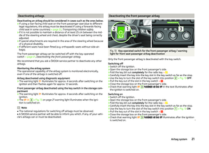 24
24 25
25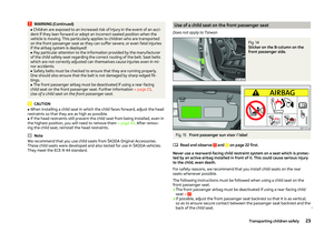 26
26 27
27 28
28 29
29 30
30 31
31 32
32 33
33 34
34 35
35 36
36 37
37 38
38 39
39 40
40 41
41 42
42 43
43 44
44 45
45 46
46 47
47 48
48 49
49 50
50 51
51 52
52 53
53 54
54 55
55 56
56 57
57 58
58 59
59 60
60 61
61 62
62 63
63 64
64 65
65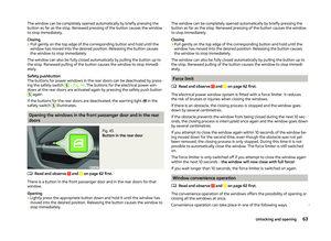 66
66 67
67 68
68 69
69 70
70 71
71 72
72 73
73 74
74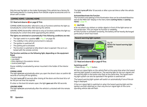 75
75 76
76 77
77 78
78 79
79 80
80 81
81 82
82 83
83 84
84 85
85 86
86 87
87 88
88 89
89 90
90 91
91 92
92 93
93 94
94 95
95 96
96 97
97 98
98 99
99 100
100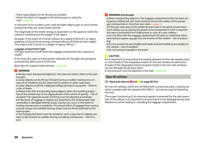 101
101 102
102 103
103 104
104 105
105 106
106 107
107 108
108 109
109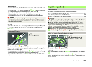 110
110 111
111 112
112 113
113 114
114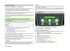 115
115 116
116 117
117 118
118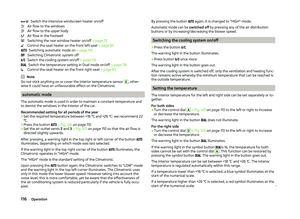 119
119 120
120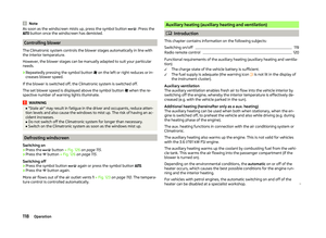 121
121 122
122 123
123 124
124 125
125 126
126 127
127 128
128 129
129 130
130 131
131 132
132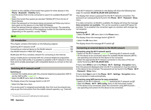 133
133 134
134 135
135 136
136 137
137 138
138 139
139 140
140 141
141 142
142 143
143 144
144 145
145 146
146 147
147 148
148 149
149 150
150 151
151 152
152 153
153 154
154 155
155 156
156 157
157 158
158 159
159 160
160 161
161 162
162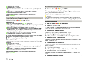 163
163 164
164 165
165 166
166 167
167 168
168 169
169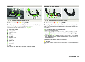 170
170 171
171 172
172 173
173 174
174 175
175 176
176 177
177 178
178 179
179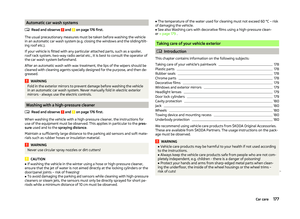 180
180 181
181 182
182 183
183 184
184 185
185 186
186 187
187 188
188 189
189 190
190 191
191 192
192 193
193 194
194 195
195 196
196 197
197 198
198 199
199 200
200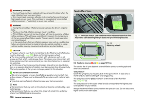 201
201 202
202 203
203 204
204 205
205 206
206 207
207 208
208 209
209 210
210 211
211 212
212 213
213 214
214 215
215 216
216 217
217 218
218 219
219 220
220 221
221 222
222 223
223 224
224 225
225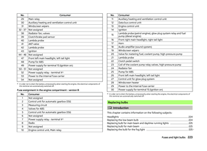 226
226 227
227 228
228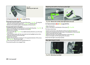 229
229 230
230 231
231 232
232 233
233 234
234 235
235 236
236 237
237 238
238 239
239 240
240 241
241 242
242 243
243 244
244 245
245 246
246 247
247 248
248 249
249 250
250 251
251