Page 169 of 252

Save tyre pressure valuesFig. 154
Key for storing the pressure val-
ues
Read and observe on page 165 first.
Saving the tyre pressure values is undertaken as follows.
›
Inflate all the tyres to the specified pressure.
›
Switch on the ignition.
›
Press and hold the symbol button
» Fig. 154 .
The warning light in the instrument cluster illuminates.
An acoustic signal and the control indicator provide information about the
storage of the tyre pressure values.
›
Release the symbol button.
The tyre pressure values are always stored in the system, if one of the follow-
ing events occurs.
› Change of tyre inflation pressure.
› Changing one or more wheels.
› Changing position of a wheel on the vehicle.
› Illumination of the warning light
in the instrument cluster.
WARNINGBefore storing the pressures, the tyres must be inflated to the specified in-
flation pressure » page 198. When storing incorrect pressure values, the
system could possibly not issue any warnings, even with a too low tyre
pressure.
CAUTION
The tyre pressure values are to be saved every 10,000 km or once annually to
ensure correct system functioning.Hitch and trailer
Hitch
Introduction
This chapter contains information on the following subjects:
Description
167
Adjusting the ready position
167
Fitting the ball head
168
Check proper fitting
168
Removing the ball head
169
Accessories
169
The maximum trailer drawbar load is 80 kg/h.
WARNING■
Check that the ball head is seated correctly and is secured in the mount-
ing recess before starting any journey.■
Do not use the ball head, if it is not correctly inserted into the mounting
recess and secured.
■
Do not use the towing equipment if it is damaged or incomplete.
■
Do not modify or adapt the towing equipment in any way.
■
Never release the ball head while the trailer is still coupled.
■
Keep the mounting recess of the towing equipment clean at all times.
Such dirt prevents the ball head from being attached securely.
CAUTION
■ Take care with the ball bar - there is a risk of paint damage to the bumper.■When the tow bar is removed always place the cover onto the mounting re-
cess - there is a danger of soiling the mounting recess.
Note
■ Operation and maintenance of hitch » page 180.■Tow the vehicle by means of the detachable ball rod » page 214.166Driving
Page 170 of 252

DescriptionFig. 155
Carrier for the towing device / tow bar
Read and observe
and on page 166 first.
The ball head can be removed and is kept in the spare wheel well or in a com-
partment for the spare wheel in the luggage compartment.
Support for the towing device and tow bar » Fig. 155
13-pin power socket
Safety eyelet
Mounting recess
Cap
Dust cap
Ball head
Operating lever
Lock cap
Release pin
Key
locking ball
Note
If you lose the key, please get in touch with a specialist garage.1234567891011Adjusting the ready positionFig. 156
Setting the ready position/ready position
Read and observe
and on page 166 first.
The coupling ball bar must be set prior to installation in the standby position.
If this is not in the ready position, then this must be set to the standby posi-
tion as follows.
›
Grip the ball head below the protective cap
2
.
›
Remove the cap from the lock.
›
Insert the key into the lock, so that its green marking is pointing upwards.
›
Turn key
1
in direction of the arrow, so that the red marking is facing up-
wards » Fig. 156 .
›
Press the release pin
3
as far as the stop in the direction of the arrow and
at the same time push the lever
4
downwards as far as it will go in the di-
rection of the arrow.
The operating lever remains locked in this position.
CAUTION
In the ready position, the key cannot be removed nor turned to a different po-
sition.167Hitch and trailer
Page 171 of 252

Fitting the ball headFig. 157
Insert the ball head/lock the lock, and put the lock cover on
Read and observe
and on page 166 first.
›
Pull cap
4
» Fig. 155 on page 167 downwards.
›
Adjust the ball head to the ready position » page 167.
›
Grip the tow bar from underneath » Fig. 157 and insert into the mounting re-
cess until you hear it click into place » .
The operating lever
1
automatically turns upwards and the release pin
2
pops out (its red and green parts are visible) » .
If the operating lever
1
does not automatically emerge, or if the release pin
2
does not pop out, remove the ball head from the mounting recess by turn-
ing the lever downwards as far as it will go. Clean the tapered surfaces on the
ball head and the mounting recess.
›
Turn the key
3
180° to the right so that its green marker points upward.
›
Remove the key in the direction of the arrow.
›
Insert and press the cap
4
onto the lock in the direction of the arrow » .
›
Check the ball head for secure mounting » page 168.
WARNING■
Keep your hands outside the lever's range of motion when attaching the
ball head – there is a risk of fingers being injured!■
Never attempt to pull the operating lever upwards forcibly to turn the
key. Doing so would mean the ball head is not attached correctly.
CAUTION■ After removing the key, always replace the cover on the lock – there is a risk
of the lock getting dirty.■
Keep the mounting recess of the towing equipment clean at all times. Such
dirt prevents the ball head from being attached securely.
Check proper fitting
Fig. 158
Correctly secured ball head
Read and observe and on page 166 first.
Check that the ball head is fitted properly each time before use.
Correctly secured ball head » Fig. 158
Lever
1
is up as far as it will go » Fig. 158.
The release pin
2
is completely exposed (both its red and green parts are
visible).
The key is removed.
Cap
3
is on the lock.
The ball head does not come out of the mounting recess even after heavy
“shaking”.
WARNINGThe towing device can only be used when the tow bar is correctly locked –
there is the risk of an accident occurring.168Driving
Page 172 of 252

Removing the ball headFig. 159
Unlock the operating lever of the ball head/removing the ball
head
Read and observe
and on page 166 first.
›
Remove cover
1
» Fig. 159 from the lock in the direction of the arrow.
›
Insert the key into the lock, so that its green marking is pointing upwards.
›
Turn the key
2
180° to the left so that its red marker points upward.
›
Grasp the ball head from underneath.
›
Press the release pin
3
as far as the stop in the direction of the arrow and
at the same time push the lever
4
downwards as far as it will go in the di-
rection of the arrow.
The ball head is released in this position and falls freely into the hand. If it
does not fall freely into the hand, use your other hand to push it upwards.
At the same time, the ball head latches into the ready position and is thus
ready to be re-inserted into the mounting recess »
.
›
Place the cap
4
» Fig. 155 on page 167 onto the mounting recess.
WARNINGNever allow the ball head to remain unsecured in the boot. This could
cause damage to the boot upon sudden braking, and could put the safety
of the occupants at risk.CAUTION■ If the lever is held firmly and not pushed downwards as far as it can go, it will
go back up after the ball head is removed and will not latch into the ready po-
sition. The ball head then needs to be brought into this position before the
next time it is fitted.■
Tuck the ball bar in the ready position, with the golden key up, in the box -
otherwise there is a risk of damage to the key!
■
Do not use excessive force when handling the operating lever (e.g. do not
step on it).
Note
■ We recommend that you put the protective cap on the ball before removing
the ball head.■
Clean any dirt from the ball head before stowing it away in the box with the
vehicle tool kit.
Accessories
Fig. 160
Representation of the maximum
permissible level of the ball head
of the towing hitch and the per-
missible total weight of the ac-
cessories including the load de-
pending on the load center of
gravity
Read and observe and on page 166 first.
An accessory can mounted on the ball head of the towing hitch (e.g. bike carri-
ers).
If this accessory is used, the maximum permissible overhang of the ball head
of the towing hitch and the permissible gross vehicle weight of the accesso-
ries including load are to be checked.
The maximum permissible overhang of the ball head of the towing hitch is 70
cm » Fig. 160 .
The total permitted weight of the accessory including load changes with in-
creasing distance of the centre of gravity of the load from the ball head of the
towing hitch.
169Hitch and trailer
Page 173 of 252

Distance of the centre of gravity ofthe load from the ball headPermissible total weight of the ac- cessory, including load0 cm80 kg30 cm75 kg60 cm35 kg70 cm0 kgWARNING■Never exceed the permissible gross weight of the accessory including
load - there is a risk of damaging the ball head of the towing hitch.■
Never exceed the permissible overhang of the ball head of the towing
hitch - there is a risk of damaging the ball head of the towing hitch.
Note
We recommend that you use accessories from ŠKODA Original Accessories.
Trailer
Introduction
This chapter contains information on the following subjects:
Attaching and detaching trailers
170
Loading a trailer
171
Towing a trailer
171
Trailer stabilisation (TSA)
172
Anti-theft alarm system
172
If your vehicle has already been factory fitted with towing equipment or is fit-
ted with towing equipment from ŠKODA Original Accessories, then it meets all
of the technical requirements and national legal provisions for towing a trailer.
Note
If there is an error in the trailer lighting system, check the fuses in the fuse box
in the dashboard » page 220.Attaching and detaching trailersFig. 161
Swivel out the 13-pin power
socket, safety eyelet
Coupling
›
Install the tow bar.
›
Grip the 13-pin socket at point
A
and swing out in the direction of ar-
row » Fig. 161 .
›
Lift off protective cap
5
» Fig. 155 on page 167 towards the top.
›
Place the trailer onto the ball.
›
Insert the trailer cable into the 13-pin socket.
If the trailer that is to be towed has a 7-pin connector, you can use a suitable
adapter from ŠKODA Original Accessories to establish a connection to the elec-
tricity.
›
Hook the breakaway cable of the trailer to the security lock slot
B
.
The breakaway cable of the trailer has to sag when mounted into the security
lock slot for all trailer positions relative to the vehicle (sharp curves, reverse
driving and the like).
Uncoupling
The uncoupling of the trailer is carried out in reverse order.
›
Unhook the breakaway cable of the trailer from the security lock slot
B
» Fig. 161 .
›
Pull the trailer cable out of the 13-pin socket.
›
Remove the trailer from the ball head.
›
Place the cover
5
on the ball head » Fig. 155 on page 167 .
›
Grip the 13-pin socket at point
A
and swing in the opposite direction to the
arrow » Fig. 161 .
170Driving
Page 174 of 252

Exterior mirrors
You have to have additional exterior mirrors fitted if you are not able to see
the traffic behind the trailer with the standard rear-view mirrors. National legal
requirements must be observed.
Headlights
The front of the vehicle can be lifted when a trailer is being towed and the
headlights can dazzle other road users.
Adjust the headlight setting on the headlight range control » page 68, Operat-
ing the lights and the instrument illumination .WARNING■
Incorrect or improperly connected electrical installation can cause acci-
dents and serious injury due to electric shock.■
Work on the electrical system must only be carried out by specialist ga-
rages.
■
Never directly connect the trailer's electrical system with the electrical
connections for the tail lights or other current sources.
■
After coupling the trailer and connecting up the power socket, check the
rear lights on the trailer to ensure they are working.
■
The handbrake on the towing vehicle must be applied when coupling and
uncoupling the trailer.
■
Never use the safety eyelet for towing!
CAUTION
Incorrect or improperly connected electrical installations may cause malfunc-
tion of the entire vehicle electronics.
Loading a trailer
The vehicle/trailer combination must be balanced, whereby the maximum per-
missible drawbar load must be utilised. If the drawbar load is too low, it jeop-
ardises the performance of the vehicle/trailer combination.
Distribution of the load
Distribute the load in the trailer in such a way that heavy items are located as
close to the axle as possible. Secure the items from slipping.
The distribution of the weight is very poor if your vehicle is unladen and the
trailer is laden. Maintain a particularly low speed if you cannot avoid driving
with this combination.
Tyre pressure
Correct the tyre inflation pressure on your vehicle for a “full load” » page 198.
Trailer load
The permissible trailer load must not be exceeded under any circumstan-
ces » page 228 , Technical data .
The details given in the vehicle's technical documentation always take prece- dence over the details in the Owner's Manual.
The trailer loads specified apply only to altitudes up to 1,000 metres above
mean sea level.
The engine output falls as altitude increases, as does the ability to climb.
Therefore, for every additional 1,000 m in height (or part), the maximum per-
missible towed weight must be reduced by 10 %.
The towed weight comprises the actual weights of the (loaded) towing vehicle
and the (loaded) trailer.
The trailer and drawbar load information on the type plate of the towing
equipment are merely test data for the towing equipment. The vehicle-specific
values are detailed in the vehicle documents.WARNING■ The maximum permissible axle and drawbar load and the permissible
weight of the trailer must not exceed - this could cause an accident!■
A sliding cargo can significantly adversely affect stability and driving safe-
ty - there is a risk of accident!
Towing a trailer
Driving speed
For safety reasons, do not drive faster than 80 km/h when towing a trailer.
Immediately reduce your speed as soon as even the slightest swaying of the
trailer is detected. Never attempt to stop the trailer from “swaying” by acceler-
ating.
Brakes
Apply the brakes in good time! If the trailer is fitted with a trailer brake, apply
the brakes gently at first and then brake firmly. This will avoid brake jolts re-
sulting from the trailer wheels locking.
On downhill sections shift down a gear in good time to also use the engine as
a brake.
171Hitch and trailer
Page 175 of 252

Engine overheating
The speed must be reduced immediately if the needle for the coolant tempera-
ture gauge moves into the right-hand area or the red area of the scale.
Stop and switch off the engine if the warning light
in the instrument cluster
illuminates.
The following guidelines must be observed » page 36,
Coolant .
The coolant temperature can be reduced by switching on the heating.WARNING■ Always drive particularly carefully with the trailer.■Adapt your speed to the conditions of the road surface and to the traffic
situation.
CAUTION
If you tow a trailer frequently, you should also have your vehicle inspected be-
tween service intervals.
Trailer stabilisation (TSA)
The trailer stabilisation is an extension of the stabilisation control that works
in conjunction with the counter-steering assistance to reduce the amount the
trailer "sways".
After turning on the ignition, the ESC warning light
in the instrument cluster
illuminates for about 2 seconds longer than the ABS warning light.
Function requirements for trailer stabilisation. The trailer was shipped from the factory or purchased from the ŠKODA
genuine accessories.
The ESC is active. (Warning lights
or
do not illuminate in the instru-
ment cluster).
The trailer is electrically connected to the towing vehicle by means of the
trailer socket.
The speed is higher than approx. 60 km/h.
The trailer has a rigid drawbar.
WARNING■ The increased safety offered by the trailer stabilisation must not tempt
you to take greater risks than otherwise.■
Avoid abrupt and sudden driving and braking manoeuvres - there is a risk
of accidents.
CAUTION
■ The trailer stabilisation need not be able to correctly detect all of driving sit-
uations.■
Light trailers that sway are not always detected and therefore stabilised ac-
cordingly by the trailer stabilisation.
■
Release the pressure on the accelerator pedal if the system is being regula-
ted.
Note
The trailer stabilisation works for both braked and unbraked trailers.
Anti-theft alarm system
When the vehicle is locked, the alarm is activated when the electrical connec-
tion to the trailer is interrupted.
Always switch off the anti-theft alarm system before a trailer is coupled or un-
coupled » page 55 .
Conditions for including a trailer in the anti-theft alarm system. The vehicle is factory fitted with an anti-theft alarm system and towing
equipment.
The trailer is electrically connected to the towing vehicle by means of the
trailer socket.
The electrical system of the vehicle and trailer is functional.
The vehicle is locked with the vehicle key and the anti-theft alarm system
is activated.
CAUTION
For technical reasons, trailers with rear LED lights cannot be connected to the
anti-theft alarm system.172Driving
Page 176 of 252

General Maintenance
Car care
Services, modifications and technical alterations
Introduction
This chapter contains information on the following subjects:
Vehicle operating under different weather conditions
173
Statutory checks
173
ŠKODA Service Partners
174
ŠKODA Original parts
174
ŠKODA Original accessories
174
Spoiler
175
Airbags
175
The instructions and guidelines from ŠKODA AUTO a.s. must be observed when
carrying out all modifications, repairs or technical alterations to your vehicle.
Adhering to these instructions and guidelines helps ensure road safety and
helps keep your vehicle in a good technical condition. After carrying out modifi-
cations, repairs or technical alterations, the vehicle will comply with German
road transport regulations (StVO)
Always consult a ŠKODA Partner » page 174before buying accessories or
parts, or before carrying out any modifications, repairs or technical alterations
to your vehicle.
WARNING■ Works on your vehicle, which have been carried out unprofessionally, can
cause operational faults – risk of accident!■
Interference on the electronic components and their software can lead to
operational faults. This interference can also impair not directly affected
systems because of the networking of the electronic components. The op-
erational safety of the vehicle may be at significant risk and can lead to in-
creased wear of parts.
For the sake of the environmentTechnical documents regarding alterations carried out on the vehicle must be
kept by the vehicle user in order to be handed over to the recyclers at a later
date. This ensures that the vehicle is recycled in an environmentally sound
manner.
Note
■ We recommend only having these modifications and technical alterations
carried out by a specialist garage.■
Any damage caused by technical alterations made without the approval of
the manufacturer is excluded from the warranty » Service schedule .
■
The ŠKODA Partner does not assume any liability for products that have not
been approved by ŠKODA AUTO a.s. even though these may be products with
an operational approval or that have been approved by a government testing
institute.
■
We advise you only to use ŠKODA Original Accessories and ŠKODA Original
Parts which have been expressly approved for use on your vehicle. Reliability,
safety and suitability for your vehicle are guaranteed with these.
■
ŠKODA Original Accessories and ŠKODA Original Parts can be purchased from
ŠKODA Partners, who will also perform the professional assembly of the pur-
chased parts.
Vehicle operating under different weather conditions
Read and observe
on page 173 first.
If you would like to operate your vehicle in countries other than those with itsintended weather conditions, you should contact a ŠKODA Partner.
He will advise you if certain precautions need to be taken to ensure the full
functioning of the vehicle as well as to prevent damage.
This involves, for example, the coolant, battery replacement and the like.
Statutory checks
Read and observe
on page 173 first.
Many countries have legislation requiring the operational reliability and roadworthiness and/or exhaust gas properties of a vehicle to be tested at specific
intervals. These tests can be carried out by workshops or testing stations that
have been legally authorised for this purpose.
173Car care
 1
1 2
2 3
3 4
4 5
5 6
6 7
7 8
8 9
9 10
10 11
11 12
12 13
13 14
14 15
15 16
16 17
17 18
18 19
19 20
20 21
21 22
22 23
23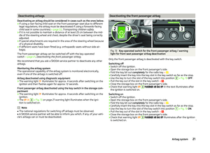 24
24 25
25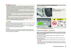 26
26 27
27 28
28 29
29 30
30 31
31 32
32 33
33 34
34 35
35 36
36 37
37 38
38 39
39 40
40 41
41 42
42 43
43 44
44 45
45 46
46 47
47 48
48 49
49 50
50 51
51 52
52 53
53 54
54 55
55 56
56 57
57 58
58 59
59 60
60 61
61 62
62 63
63 64
64 65
65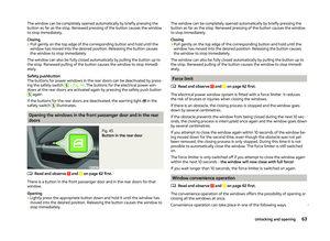 66
66 67
67 68
68 69
69 70
70 71
71 72
72 73
73 74
74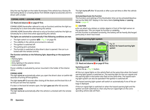 75
75 76
76 77
77 78
78 79
79 80
80 81
81 82
82 83
83 84
84 85
85 86
86 87
87 88
88 89
89 90
90 91
91 92
92 93
93 94
94 95
95 96
96 97
97 98
98 99
99 100
100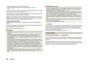 101
101 102
102 103
103 104
104 105
105 106
106 107
107 108
108 109
109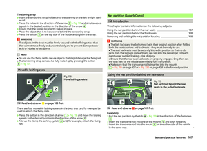 110
110 111
111 112
112 113
113 114
114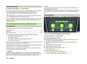 115
115 116
116 117
117 118
118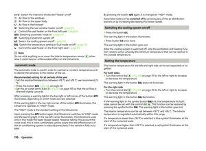 119
119 120
120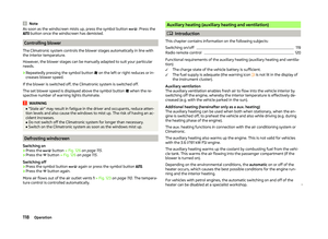 121
121 122
122 123
123 124
124 125
125 126
126 127
127 128
128 129
129 130
130 131
131 132
132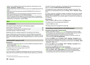 133
133 134
134 135
135 136
136 137
137 138
138 139
139 140
140 141
141 142
142 143
143 144
144 145
145 146
146 147
147 148
148 149
149 150
150 151
151 152
152 153
153 154
154 155
155 156
156 157
157 158
158 159
159 160
160 161
161 162
162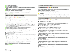 163
163 164
164 165
165 166
166 167
167 168
168 169
169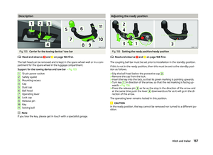 170
170 171
171 172
172 173
173 174
174 175
175 176
176 177
177 178
178 179
179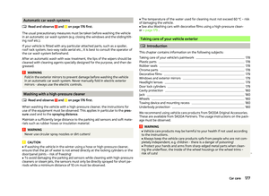 180
180 181
181 182
182 183
183 184
184 185
185 186
186 187
187 188
188 189
189 190
190 191
191 192
192 193
193 194
194 195
195 196
196 197
197 198
198 199
199 200
200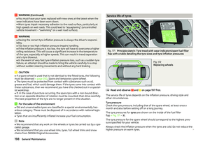 201
201 202
202 203
203 204
204 205
205 206
206 207
207 208
208 209
209 210
210 211
211 212
212 213
213 214
214 215
215 216
216 217
217 218
218 219
219 220
220 221
221 222
222 223
223 224
224 225
225 226
226 227
227 228
228 229
229 230
230 231
231 232
232 233
233 234
234 235
235 236
236 237
237 238
238 239
239 240
240 241
241 242
242 243
243 244
244 245
245 246
246 247
247 248
248 249
249 250
250 251
251