Page 177 of 212

CAUTION
Switch off the air compressor after running 8 minutes at the latest - danger of
overheating! Allow the air compressor to cool a few moments before switching it
on again.
Check after driving for 10 minutes Check the tyre inflation pressure after driving 10 minutes.
If the tyre inflation pressure is 1.3 bar or less:
–
Do not drive the vehicle! You cannot properly seal with tyre with the break-
down kit.
– Contact a Škoda dealer to obtain professional assistance.
If the tyre inflation pressure is 1.3 bar or more:
– Adjust the tyre inflation pressure to the correct value (see inside of fuel filler
cap).
– Continue driving carefully to the nearest specialist garage at a maximum
speed of 80 km/h (50 mph).
Jump-starting Initial steps You can use the battery of another vehicle for jump-starting yours if the engine
does not start because the battery on your vehicle is flat. You will require jump-
start cables for this purpose.
Both batteries must have a rated voltage of 12 V. The capacity
(Ah) of the battery
supplying the power must not be significantly less than the capacity of the dis-
charged battery in your vehicle.
Jump-start cables
Only use jump-start cables which have an adequately large cross-section and in-
sulated terminal clamps. Please pay attention to the manufacturer's instructions.
Positive cable - colour coding in the majority of cases red.
Negative cable -
colour coding in the majority of cases black. WARNING
● A discharged battery may already freeze at temperatures just below 0 °C.
In case of frozen battery carry out no jump-starting - risk of explosion! Also af-
ter thawing of the battery there is a risk of caustic burns due to leaking acid.
Replace the frozen battery.
● Please pay attention to the warning instructions relating to working in the
engine compartment ⇒ page 150
. Note
● There must not be any contact between the two vehicles otherwise current
may flow as soon as the negative terminals are connected.
● The discharged battery must be properly connected to the system of the vehi-
cle.
● Switch off the car phone. Heed the advice concerning the use of mobile
phones in such a situation.
● We recommend you buy jump-start cables from a car battery specialist.
Start engine Fig. 142 Jump-starting using the battery
from another vehicle: A - flat vehicle bat-
tery, B - battery providing current
It is important to connect the jump-start cables in the correct order.
Connecting positive terminals
– Attach one end 1 to the positive terminal
⇒ fig. 142 of the discharged battery
A .
– Attach the other end 2 to the positive terminal of the battery supplying the
power B .
£ 175
Breakdown assistance Using the system Safety Driving Tips General Maintenance Breakdown assis-
tance Praktik Technical data
Page 178 of 212

Connecting negative terminal and engine block
– Attach one end 3 to the negative terminal of the battery supplying the power
B .
– Attach the other end 4 to a solid metal part which is connected firmly to the
engine block, or to the engine block itself ⇒ .
Starting engine
– Start the engine of the vehicle providing current and run the engine at idling
speed.
– Now start the engine of the vehicle with the discharged battery.
– Interrupt the attempt at starting an engine after 10 seconds if it does not start
right away and wait for about 30 seconds before repeating the attempt.
– Disconnect the cables in exactly the reverse order they were connected.WARNING
● The non-insulated parts of the terminal clamps must never make contact
with each other. In addition, the jump-start cable connected to the positive
terminal of the battery must not come into contact with electrically conduct-
ing parts of the vehicle - risk of short circuit!
● Do not affix the jump starting cables to the negative terminal of the dis-
charged battery. There is the risk of detonating gas seeping out the battery
being ignited by the strong spark which results from the engine being started.
● Do not affix the cable end 4 to parts of the fuel and brake system.
● Run the jump-start cables so that they cannot be caught by any rotating
parts in the engine compartment.
● Do not bend over the batteries - risk of caustic burns!
● The vent screws of the battery cells must be tightened firmly.
● Keep any sources of ignition (naked flame, smouldering cigarettes etc.)
away from the battery - risk of an explosion!
● Never jump-start the batteries which have a too low electrolyte level - risk
of explosion and caustic burns! Jump-starting on vehicles with the “START-STOP” system
Fig. 143 Jump-starting on vehicles with
the START-STOP system
On vehicles with the “START STOP” system, the negative cable of the charger
must never be connected directly to the negative pole of the vehicle battery, but
only to the engine earth ⇒ fig. 143 .
Towing the vehicle General Vehicles with manual transmission can be towed in with a tow bar or a tow rope
or with the front or rear wheels raised.
Vehicles with automatic transmission can be towed in with a tow bar or a tow
rope or with the front wheels raised. If the vehicle is raised at rear, the automatic
gearbox is damaged!
A tow bar
is safest way of towing a vehicle and also minimizes any shocks. You
can use a tow rope only if a suitable tow bar is not available.
Refer to the following guidelines when towing:
Driver of the towing vehicle
– Release the clutch particularly gently when starting off or depress the acceler-
ator particularly gently if your vehicle is fitted with an automatic gearbox.
– On vehicles with manual transmission, only push down on the accelerator ped-
al once the rope is taught.
The maximum towing speed is 50 km/h. £176
Breakdown assistance
Page 179 of 212

Driver of the towed vehicle
–
Switch the ignition on so that the steering wheel is not blocked and you can
also operate the turn signal lights, the headlight flasher, the windshield wipers
and windshield washer system.
– Take the vehicle out of gear or move the selector lever into position N if your
vehicle is fitted with an automatic gearbox.
Note that the brake servo unit and power steering only operate if the engine is
running. You will require significantly greater physical force to depress the brake
pedal and to steer the vehicle if the engine is not running.
Ensure that the tow rope is always kept taught. CAUTION
● Do not tow start the engine - danger of damaging the engine. On vehicles with
a catalytic converter, unburnt fuel may get into the catalytic converter where it
may ignite. This in turn may damage or destroy the catalytic converter. You can
use the battery of another vehicle as a jump-start aid ⇒ page 175,
Jump-starting.
● If the gearbox of your vehicle no longer contains any oil because of a defect,
your vehicle must only be towed in with the driven wheels raised clear of the
ground, or on a special vehicle transporter or trailer.
● The vehicle must be transported on a special vehicle or trailer if it is not possi-
ble to tow in the vehicle in the way described or if the towing distance is greater
than 50
km.
● To protect both vehicles when tow-starting or towing, the tow rope should be
elastic. Thus one should only use plastic fibre rope or a rope made out of a similar-
ly elastic material.
● One should be constantly vigilant not to allow impermissibly high towing
forces or jerky loadings. There is always a risk of excessive stresses and damage
resulting at the points to which you attach the tow rope or tow bar when you at-
tempt to tow a vehicle which is not standing on a paved road.
● Attach the tow rope or the tow bar only to the towing eyes provided for this
purpose ⇒ page 177
, Front towing eye and ⇒ page 178, Rear towing eye. Note
● We recommend a tow rope from the range of
ŠKODA Original Accessories that
you can purchase from an authorised ŠKODA Service Partner.
● Towing another vehicle requires a certain amount of practice. Both drivers
should be familiar with the particular points about towing a vehicle. Unskilled driv-
ers should not attempt to tow in another vehicle or to be towed in. ●
When towing, respect the national legal provisions, especially those which re-
late to the identification of the towing vehicle and the vehicle being towed.
● The tow rope must not be twisted as it may in certain circumstances result in
the front towing eye being unscrewed out of your vehicle.
Front towing eye The towing eye is stored in the box of the vehicle tool kit.
Fig. 144 Front bumper: Cover/installing the towing eye
–
Press on the left half of the cover at the point of the arrow ⇒
fig. 144 - left.
– Pull the cover out of the front bumper.
– Screw in the towing eye by hand to the left up to the stop ⇒ fig. 144 - right. For
tightening, we recommend that you use for example the wheel wrench, the
lashing eye of another vehicle or a similar object which you can push through
the eye.
– In order to reinstall the cover after screwing out the towing eye, insert it in the
mounts and then press on the right side of the cover. The cover must engage
firmly. CAUTION
The towing eye must always be screwed in fully and firmly tightened, otherwise
the towing eye can tear when towing. 177
Breakdown assistance Using the system Safety Driving Tips General Maintenance Breakdown assis-
tance Praktik Technical data
Page 180 of 212
Rear towing eye
Fig. 145 Rear towing eye
The rear towing eye is located below the rear bumper on the right ⇒ fig. 145 . 178
Breakdown assistance
Page 181 of 212

Fuses and light bulbs
Electric fuses Replacing fuses in the dash panel Replace the defect fuse by a new fuse of the same ampere number.
Fig. 146 Bottom side of the dash panel:
fuse cover
Individual electrical circuits are protected by fuses. The fuses are located on the
left side of the dash panel behind the safety cover.
– Switch the ignition off and also the electrical component affected.
– Carefully swivel the cover in the direction of arrow and pull it out ⇒ fig. 146 .
– Find out which fuse belongs to the component which is not operating
⇒ page 180
, Fuse assignment in the dash panel.
– Take the plastic clip out of its fixture in the fuse cover, insert it onto the re-
spective fuse and pull out this fuse.
– Defect fuses can be detected by their melted metal strips. Replace the defect
fuse by a new fuse of the same ampere number.
– Insert the fuse cover into the dash panel in such a way that the guide lugs are
guided into the openings of the dash panel and then lock them by pressing.
We recommend that you always have replacement fuses in your vehicle. You can
obtain replacement fuses from the range of
ŠKODA Original Parts or from a spe-
cialist garage. Colour coding of fuses Colour Maximum amperage
light brown 5
brown 7,5
red 10
blue 15
yellow 20
white 25
green 30
WARNING
Read and observe the warning notes ⇒ page 150
, Working in the engine com-
partment before working in the engine compartment. CAUTION
● Never attempt to
“repair” fuses and also do not replace them with a fuse of a
higher amperage - risk of fire! This may also cause damage at another part of the
electrical system.
● Have the electrical system checked as quickly as possible by a specialist ga-
rage if a newly inserted fuse blows again after a short time. Note
We recommend that you have these fuses replaced by a specialist garage. 179
Fuses and light bulbs Using the system Safety Driving Tips General Maintenance Breakdown assis-
tance Praktik Technical data
Page 182 of 212

Fuse assignment in the dash panel
Fig. 147 Schematic representation of the fuse box for vehicles with left-hand steering/right-
hand steering
Certain electrical components are only standard on certain vehicle model versions
or only available as optional equipment for certain models. No. Power consumer
1 S-contact
2 START - STOP
3 Instrument cluster, headlight range adjustment
4 ABS control unit
5 Petrol engine: Speed regulating system
6 Reversing light (manual gearbox)
7 Ignition
Engine control unit, automatic gearbox
8 Brake pedal switch, coolant fan
9 Operating controls for the heating, control unit for air conditioning sys-
tem, parking aid, control unit for cornering lights, coolant fan
10 The air conditioning system
11 Mirror adjustment
12 Control unit for trailer detection
13 Control unit for automatic gearbox
14 Motor for halogen projector headlights with cornering light function
15 Radio navigation system PDA
16 Electrohydraulic power steering No. Power consumer
17 START - STOP - radio
Daylight driving lights
18 Mirror heater
19 S-contact
20 Anti-theft alarm system
21 Reversing light, fog lights with the function “CORNER”
22 Operating controls for the heating, control unit for air conditioning sys-
tem, parking aid, mobile phone, instrument cluster, steering angle
sender, ESP, vehicle voltage control unit, multifunction steering wheel
23 Interior lighting, storage compartment and luggage compartment, side
lights
24 Central control unit of the vehicle
25 Seat heaters
26 Rear window wiper
27 Telephone preinstallation
28 Petrol engine: AKF valve, petrol engine: Control flap
29 Injection, water pump
30 Fuel pump
Ignition
Cruise control system, operation of PTC relay
31 Lambda probe
32 High pressure pump, pressure valve
33 Engine control unit
34 Engine control unit
Vacuum pump
35 Power supply of ignition lock
36 Main beam
37 Rear fog light
38 Fog lights
39 Blower
40 Heatable windshield washing nozzles, windshield cleaning system
41 Not assigned
42 Rear window heater
£180
Fuses and light bulbs
Page 183 of 212

No. Power consumer
43 Horn
44 Front window wiper
45 Central control unit for convenience system
46 Engine control unit
Engine control unit
Fuel pump relay
Fuel pump control unit
47 Cigarette lighter, power socket in the luggage compartment
a)48 ABS, START-STOP - DC/DC converter ESP
49 Turn signal lights, brake lights
50 START-STOP - DC/DC converter infotainment
Radio
51 Electrical power window (front and rear) - left side
52 Electrical power window (front and rear) - right side
53 Parking light - left side
Electric sliding/tilting roof
54 START-STOP - instrument cluster
Anti-theft alarm system
55 Control unit for automatic gearbox DSG
56 Headlight cleaning system
Parking light - right side
57 Left low beam, headlight range adjustment
58 Low beam on the right
a)
If the engine is switched off already one electrical component which is connected can discharge the
battery. Replacing fuses at the battery (manual gearbox, automatic
gearbox DSG) Fig. 148 The battery: fuse cover
– Press together the interlocks of the fuse cover simultaneously in direction of
arrow A
⇒ fig. 148 and push out the cover in direction of arrow B .
– Release the fixtures in the openings C using a flat screwdriver and fold the
cover upwards in direction of arrow D .
– Find out which fuse belongs to the component which is not operating.
– Defect fuses can be detected by their melted metal strips. Replace the defect
fuse by a new fuse of the same ampere number. WARNING
Read and observe the warning notes ⇒ page 150 , Working in the engine com-
partment before working in the engine compartment. CAUTION
● Never attempt to
“repair” fuses and also do not replace them with a fuse of a
higher amperage - risk of fire! This may also cause damage at another part of the
electrical system.
● Have the electrical system checked as quickly as possible by a specialist ga-
rage if a newly inserted fuse blows again after a short time. Note
We recommend that you have these fuses replaced by a specialist garage. 181
Fuses and light bulbs Using the system Safety Driving Tips General Maintenance Breakdown assis-
tance Praktik Technical data
Page 184 of 212
 Fig. 149 Schematic representation of
fuse assignment at battery
Certain electrical components are only standard on certain vehic")
Fuse assignment at the battery (manual gearbox, automatic
gearbox DSG) Fig. 149 Schematic representation of
fuse assignment at battery
Certain electrical components are only standard on certain vehicle model versions
or only available as optional equipment for certain models. No. Power consumer
1 Generator
2 Not assigned
3 Interior
4 Electrical auxiliary heating system
5 Interior
6 Glow plugs, coolant fan
7 Electrohydraulic power steering
8 ABS or TCS or ESP
9 The radiator fan
10 Automatic gearbox
11 ABS or TCS or ESP
12 Central control unit
13 Electrical auxiliary heating system
CAUTION
Please refer to the following guidelines ⇒ in Replacing fuses at the battery
(manual gearbox, automatic gearbox DSG) on page 181 . Note
The fuses 1 - 7 can be replaced by a specialist garage. Replace fuses at the battery (automatic gearbox)
Fig. 150 The battery: Open the positive terminal cover/fuse cover
–
Open the positive terminal cover (+) ⇒ fig. 150.
– Press onto the interlocks of the fuse covers A
⇒
fig. 150 on the right and open
the covers.
– Press together the interlocks of the fuse cover B simultaneously and push
out the cover in the direction of the arrow.
– Find out which fuse belongs to the component which is not operating
⇒ page 182, Fuse assignment at the battery (manual gearbox, automatic gear-
box DSG)
.
– Defect fuses can be detected by their melted metal strips. Replace the defect
fuse by a new fuse of the same ampere number. WARNING
Read and observe the warning notes ⇒ page 150
, Working in the engine com-
partment before working in the engine compartment. CAUTION
● Never attempt to
“repair” fuses and also do not replace them with a fuse of a
higher amperage - risk of fire! This may also cause damage at another part of the
electrical system.
● Have the electrical system checked as quickly as possible by a specialist ga-
rage if a newly inserted fuse blows again after a short time. £182
Fuses and light bulbs
 1
1 2
2 3
3 4
4 5
5 6
6 7
7 8
8 9
9 10
10 11
11 12
12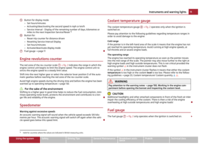 13
13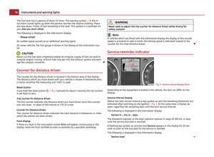 14
14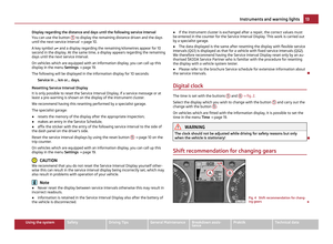 15
15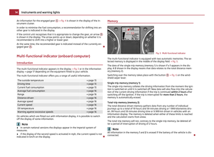 16
16 17
17 18
18 19
19 20
20 21
21 22
22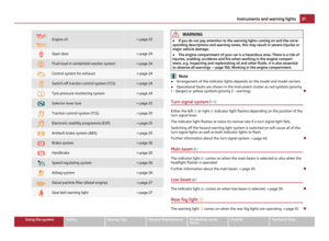 23
23 24
24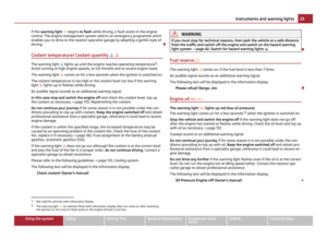 25
25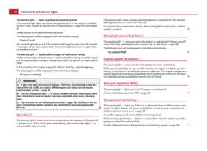 26
26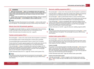 27
27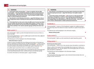 28
28 29
29 30
30 31
31 32
32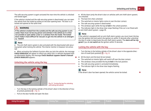 33
33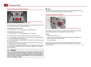 34
34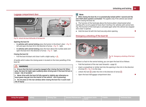 35
35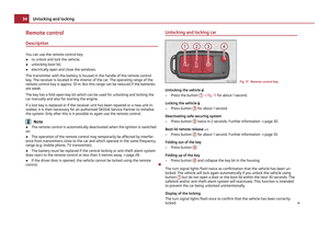 36
36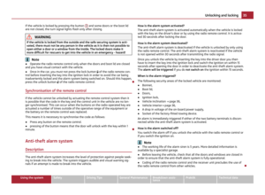 37
37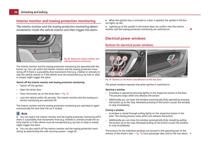 38
38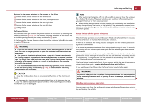 39
39 40
40 41
41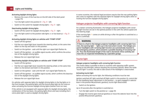 42
42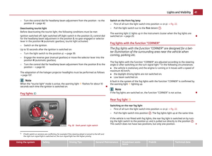 43
43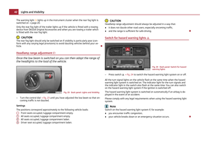 44
44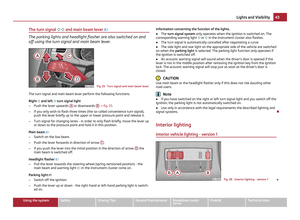 45
45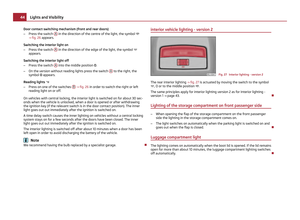 46
46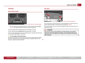 47
47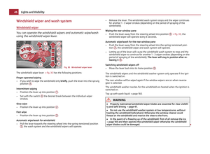 48
48 49
49 50
50 51
51 52
52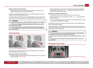 53
53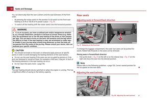 54
54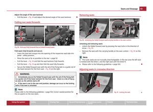 55
55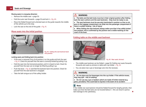 56
56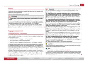 57
57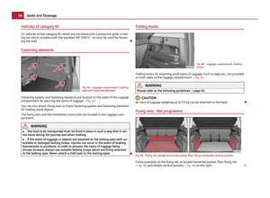 58
58 59
59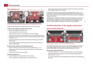 60
60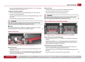 61
61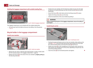 62
62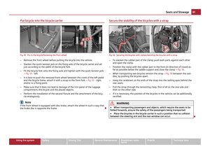 63
63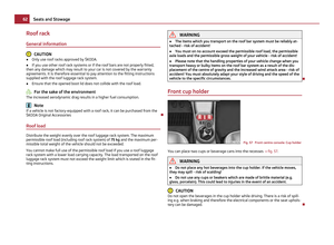 64
64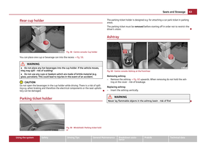 65
65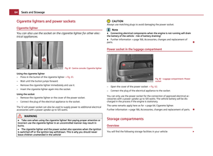 66
66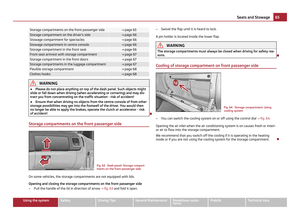 67
67 68
68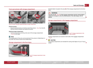 69
69 70
70 71
71 72
72 73
73 74
74 75
75 76
76 77
77 78
78 79
79 80
80 81
81 82
82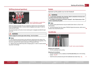 83
83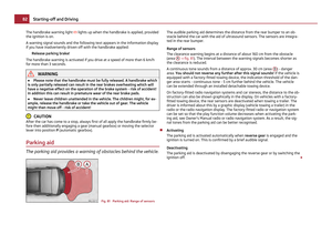 84
84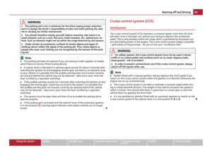 85
85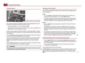 86
86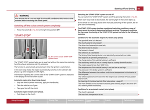 87
87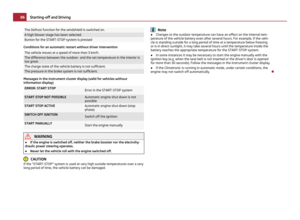 88
88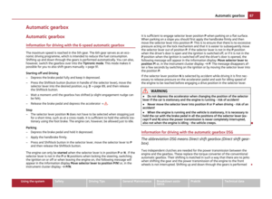 89
89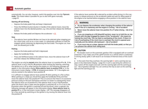 90
90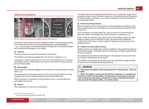 91
91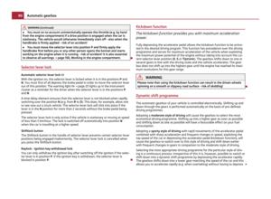 92
92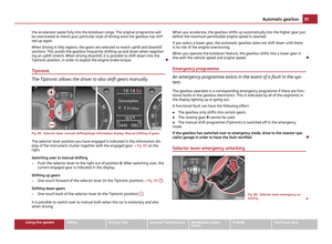 93
93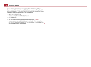 94
94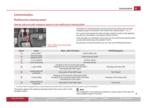 95
95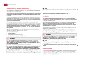 96
96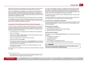 97
97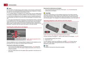 98
98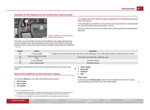 99
99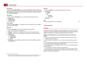 100
100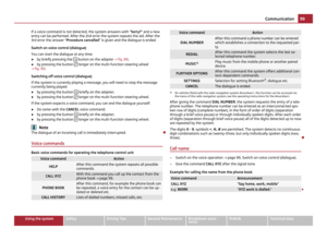 101
101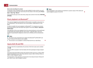 102
102 103
103 104
104 105
105 106
106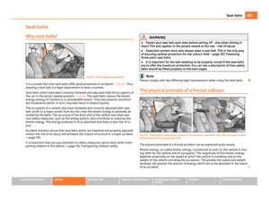 107
107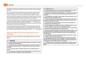 108
108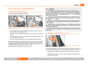 109
109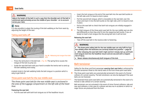 110
110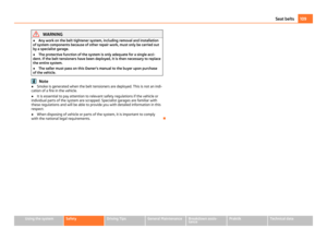 111
111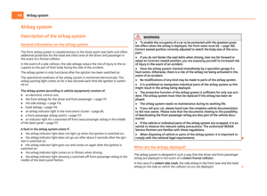 112
112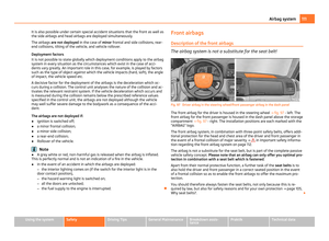 113
113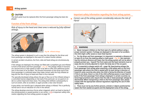 114
114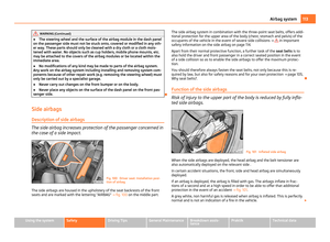 115
115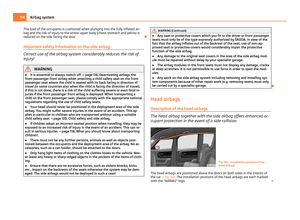 116
116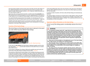 117
117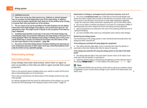 118
118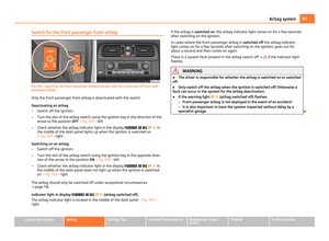 119
119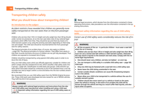 120
120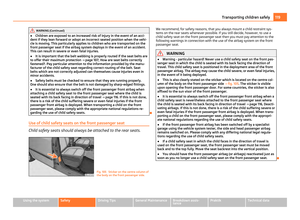 121
121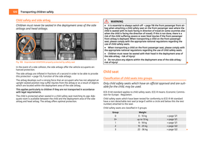 122
122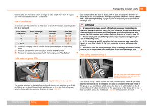 123
123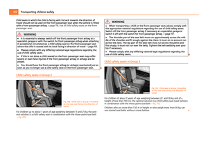 124
124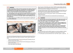 125
125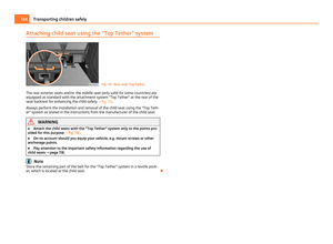 126
126 127
127 128
128 129
129 130
130 131
131 132
132 133
133 134
134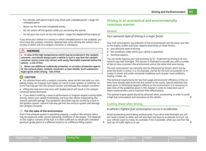 135
135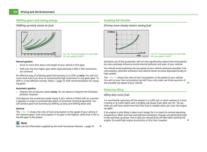 136
136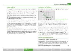 137
137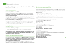 138
138 139
139 140
140 141
141 142
142 143
143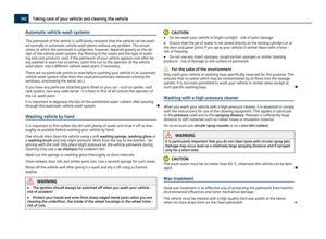 144
144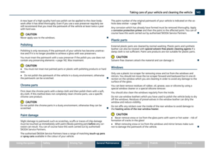 145
145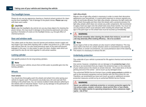 146
146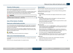 147
147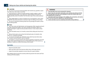 148
148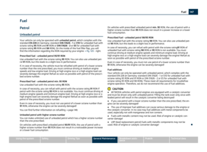 149
149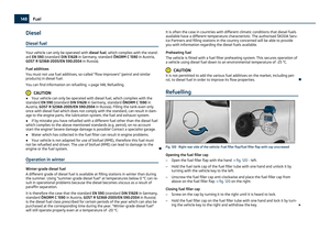 150
150 151
151 152
152 153
153 154
154 155
155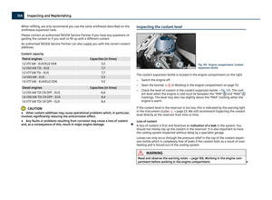 156
156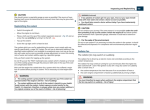 157
157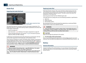 158
158 159
159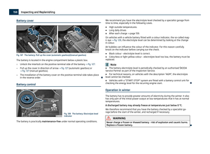 160
160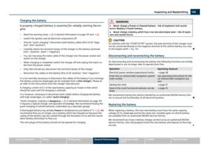 161
161 162
162 163
163 164
164 165
165 166
166 167
167 168
168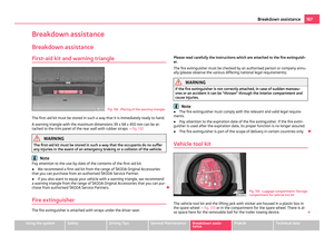 169
169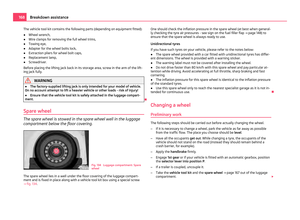 170
170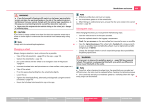 171
171 172
172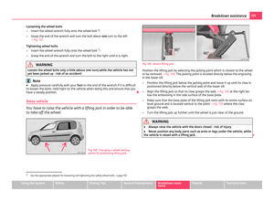 173
173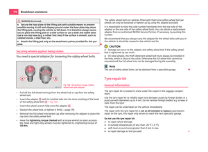 174
174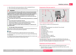 175
175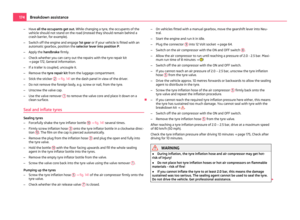 176
176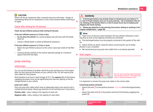 177
177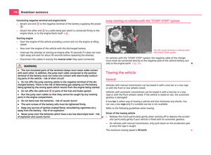 178
178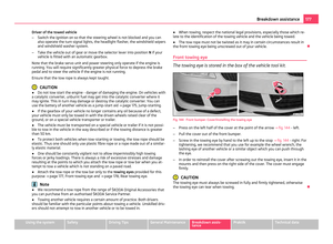 179
179 180
180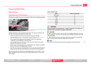 181
181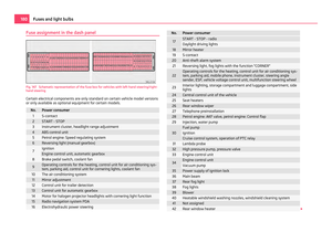 182
182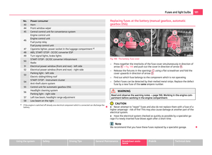 183
183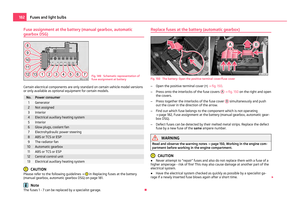 184
184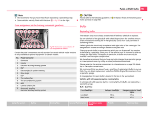 185
185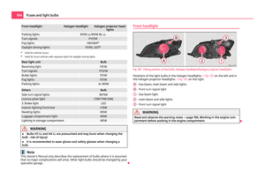 186
186 187
187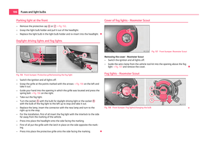 188
188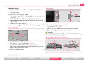 189
189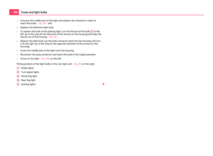 190
190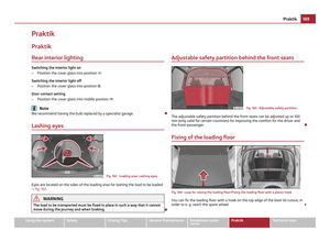 191
191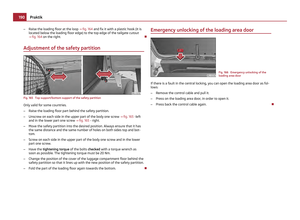 192
192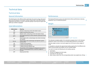 193
193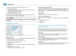 194
194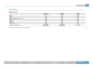 195
195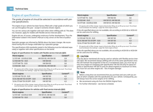 196
196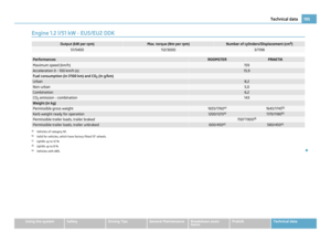 197
197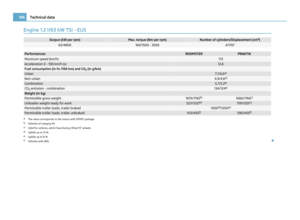 198
198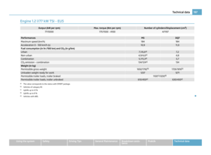 199
199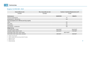 200
200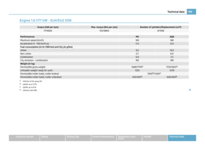 201
201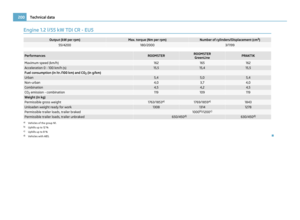 202
202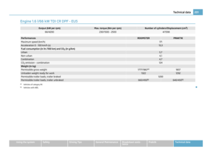 203
203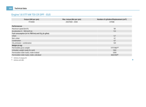 204
204 205
205 206
206 207
207 208
208 209
209 210
210 211
211