Page 169 of 212

Breakdown assistance
Breakdown assistance
First-aid kit and warning triangle Fig. 132 Placing of the warning triangle
The first-aid kit must be stored in such a way that it is immediately ready to hand.
A warning triangle with the maximum dimensions 39 x 68 x 450 mm can be at-
tached to the trim panel of the rear wall with rubber straps ⇒ fig. 132 WARNING
The first-aid kit must be stored in such a way that the occupants do no suffer
any injuries in the event of an emergency braking or a collision of the vehicle. Note
Pay attention to the use-by-date of the contents of the first-aid kit.
● We recommend a first-aid kit from the range of ŠKODA Original Accessories
that you can purchase from an authorised
ŠKODA Service Partner.
● If you also want to equip your vehicle with a warning triangle, we recommend
a warning triangle from the range of
ŠKODA Original Accessories that you can pur-
chase from authorised ŠKODA Service Partners.
Fire extinguisher The fire extinguisher is attached with straps under the driver seat. Please read carefully the instructions which are attached to the fire extinguish-
er.
The fire extinguisher must be checked by an authorised person or company annu-
ally (please observe the various differing national legal requirements). WARNING
If the fire extinguisher is not correctly attached, in case of sudden manoeu-
vres or an accident it can be
“thrown” through the interior compartment and
cause injuries. Note
● The fire extinguisher must comply with the relevant and valid legal require-
ments.
● Pay attention to the expiration date of the fire extinguisher. If the fire extin-
guisher is used after the expiration date, its proper function is no longer assured.
● The fire extinguisher is part of the scope of delivery in certain countries only.
Vehicle tool kit Fig. 133 Luggage compartment: Storage
compartment for vehicle too kit
The vehicle tool kit and the lifting jack with sticker are housed in a plastic box in
the spare wheel ⇒ fig. 133 or in the compartment for the spare wheel. There is al-
so space here for the removable ball for the trailer towing device. £ 167
Breakdown assistance Using the system Safety Driving Tips General Maintenance Breakdown assis-
tance Praktik Technical data
Page 170 of 212
:
●
Wheel wrench,
● Wire clamps for removing the full wheel trims,
● Towing eye,
● Adapter for the wheel bolts")
The vehicle tool kit contains the following parts (depending on equipment fitted):
●
Wheel wrench,
● Wire clamps for removing the full wheel trims,
● Towing eye,
● Adapter for the wheel bolts lock,
● Extraction pliers for wheel bolt caps,
● Replacement lamp,
● Screwdriver.
Before placing the lifting jack back in its storage area, screw in the arm of the lift-
ing jack fully. WARNING
● The factory-supplied lifting jack is only intended for your model of vehicle.
On no account attempt to lift a heavier vehicle or other loads - risk of injury!
● Ensure that the vehicle tool kit is safely attached in the luggage compart-
ment.
Spare wheel The spare wheel is stowed in the spare wheel well in the luggage
compartment below the floor covering.
Fig. 134 Luggage compartment: Spare
wheel
The spare wheel lies in a well under the floor covering of the luggage compart-
ment and is fixed in place along with a vehicle tool kit box using a special screw
⇒ fig. 134. One should check the inflation pressure in the spare wheel (at best when general-
ly checking the tyre air pressures - see sign on the fuel filler flap
⇒ page 148
) to
ensure that the spare wheel is always ready to use.
Unidirectional tyres
If you have such tyres on your vehicle, please refer to the notes below:
● The spare wheel provided with a car fitted with unidirectional tyres has differ-
ent dimensions. The wheel is provided with a warning sticker.
● The warning label must not be covered after installing the wheel.
● Do not drive faster than 80 km/h with this spare wheel and pay particular at-
tention while driving. Avoid accelerating at full throttle, sharp braking and fast
cornering.
● The inflation pressure for this spare wheel is identical to the inflation pressure
of the standard tyres.
● Use this spare wheel only to reach the nearest specialist garage as it is not in-
tended for continuous use.
Changing a wheel Preliminary work The following steps should be carried out before actually changing the wheel.
– If it is necessary to change a wheel, park the vehicle as far away as possible
from the traffic flow. The place you choose should be level.
– Have all the occupants get out. While changing a tyre, the occupants of the
vehicle should not stand on the road (instead they should remain behind a
crash barrier, for example).
– Apply the handbrake firmly.
– Engage 1st gear or if your vehicle is fitted with an automatic gearbox, position
the selector lever into position P .
– If a trailer is coupled, uncouple it.
– Take the vehicle tool kit and the spare wheel ⇒
page 167 out of the luggage
compartment. £168
Breakdown assistance
Page 171 of 212

WARNING
● If you find yourself in flowing traffic switch on the hazard warning lights
system and place the warning triangle on the side of the road at the prescri-
bed distance from your vehicle. Comply with the national legal regulations. In
this way you are protecting not only yourself but also other road users.
● Never start the engine with the vehicle sitting on the raised jack - danger
of suffering injury. CAUTION
If you have to change a wheel on a slope first block the opposite wheel with a
stone or similar object in order to secure the vehicle from unexpectedly rolling
away. Note
Comply with the national legal regulations.
Changing a wheel Always change a wheel on a level surface as far as possible.
–
Take off the full wheel trim ⇒ page 170 or the caps ⇒ page 170.
– Slacken the wheel bolts ⇒ page 170.
– Jack up the vehicle until the wheel to be changed is clear of the ground
⇒ page 171.
– Unscrew the wheel bolts and place them on a clean surface (cloth, paper, etc.).
– Take off the wheel.
– Fit on the spare wheel and tighten the wheel bolts slightly.
– Lower the car.
– Tighten the wheel bolts firmly, alternately and diagonally using the wrench
(crosswise) ⇒ page 170.
– Mount the full wheel trim/wheel trim cap or the caps. Note
● All bolts must be clean and must turn easily.
● You must never grease or oil the wheel bolts!
● When fitting on unidirectional tyres, ensure that the tyres rotate in the correct
direction ⇒ page 161
.
Subsequent steps After changing the wheel, you must perform the following steps.
–
Stow the vehicle tool kit in the space provided.
– Stow the replaced wheel in the luggage compartment.
– Check the tyre pressure on the spare wheel just mounted as soon as possible.
– Have the tightening torque of the wheel bolts checked with a torque wrench
as soon as possible. Steel and light alloy wheels must be tightened to a tight-
ening torque of 120
Nm.
– Change the damaged wheel or consult a specialist garage about possibilities
for getting repairs done. WARNING
It is necessary to observe the guidelines given on ⇒
page 163, New tyres and
wheels if the vehicle is subsequently fitted with tyres which are different to
those it was fitted with at the works. Note
● If you find, when changing the wheel, that the wheel bolts are corroded and
difficult to turn, the bolts must be replaced before checking the tightening torque.
● Drive cautiously and only at a moderate speed to a workshop where the tight-
ening torque can be checked. 169
Breakdown assistance Using the system Safety Driving Tips General Maintenance Breakdown assis-
tance Praktik Technical data
Page 172 of 212

Full wheel trim
Fig. 135 Removing the full wheel trim
Pulling off
– Hook the clamp found in the vehicle tool kit into the reinforced edge of the full
wheel trim.
– Push the wheel key through the clamp, support the wheel key on the tyre and
pull off the wheel trim ⇒ fig. 135 .
Install
– First press the full wheel trim onto the wheel at the valve opening provided.
Then press the full wheel trim into the wheel in such a way that its entire cir-
cumference locks correctly in place. CAUTION
● Use the pressure of your hand, do not knock on the full wheel trim! Heavy
knocks mainly on the points where the full wheel trim has not been inserted into
the wheel, can result in damage to the guide and centring elements of the full
wheel trim.
● Check for yourself that the safety wheel bolt is located in the hole in the area
of the valve before fitting the full wheel trim onto a steel wheel which is attached
with a safety wheel bolt ⇒
page 172, Securing wheels against being stolen. Wheel bolts with caps The caps are designed to protect the wheel bolts.
Fig. 136 : Pull off cap from the wheel
bolt
Pulling off
– Insert the plastic clip (in the car tool kit) sufficiently far onto the cap until the
inner catches of the clip are positioned at the collar of the cap.
– Pull the cap off with the plastic clip ⇒ fig. 136 .
Install
– Insert the caps onto the bolts.
Slackening and tightening wheel bolts Loosen the wheel bolts before jacking up the vehicle.
Fig. 137 : Loosening the wheel bolts
£170
Breakdown assistance
Page 173 of 212

.
– Grasp the end of the wrench and turn the bolt about one turn to the left
⇒ fig. 137.
Tightening wheel bol")
Loosening the wheel bolts
–
Insert the wheel wrench fully onto the wheel bolt 1)
.
– Grasp the end of the wrench and turn the bolt about one turn to the left
⇒ fig. 137.
Tightening wheel bolts
– Insert the wheel wrench fully onto the wheel bolt 1 )
.
– Grasp the end of the wrench and turn the bolt to the right until it is tight. WARNING
Loosen the wheel bolts only a little (about one turn) while the vehicle has not
yet been jacked up - risk of an accident!. Note
● Apply pressure carefully with your foot to the end of the wrench if it is difficult
to loosen the bolts. Hold tight on the vehicle when doing this and ensure that you
have a steady position.
Raise vehicle You have to raise the vehicle with a lifting jack in order to be able
to take off the wheel.
Fig. 138 Changing a wheel: Jacking
points for positioning lifting jack Fig. 139 Attach lifting jack
Position the lifting jack by selecting the jacking point which is closest to the wheel
to be removed
⇒ fig. 138 . The jacking point is located directly below the engraving
in the lower sill.
– Position the lifting jack below the jacking point and move it up until its claw is
positioned directly below the vertical web of the lower sill.
– Align the lifting jack so that its claw grasps the web ⇒ fig. 139 at the right be-
low the embossing in the side surface of the base plate.
– Make sure that the base plate of the lifting jack rests with its entire surface on
level ground and is located vertical to the point ⇒
fig. 139 where the claw
grasps the web.
– Turn the lifting jack up further until the wheel is just clear of the ground. WARNING
● Always raise the vehicle with the doors closed - risk of injury.
● Never position any body parts such as arms or legs under the vehicle, while
the vehicle is raised with a lifting jack. £1)
Use the appropriate adapter for loosening and tightening the safety wheel bolts ⇒ page 172. 171
Breakdown assistance Using the system Safety Driving Tips General Maintenance Breakdown assis-
tance Praktik Technical data
Page 174 of 212

● Secure the base plate of the lifting jack with suitable means to prevent
possible moving. A soft and slippery ground under the base plate may move
the lifting jack, causing the")
WARNING (Continued)
● Secure the base plate of the lifting jack with suitable means to prevent
possible moving. A soft and slippery ground under the base plate may move
the lifting jack, causing the vehicle to fall down. It is therefore always neces-
sary to place the lifting jack on a solid surface or use a wide and stable base.
Use a non-slip base (e.g. a rubber foot mat) if the
surface is smooth, such as
cobbled stones, a tiled floor, etc.
● Attach the lifting jack only at the attachment points provided for this pur-
pose.
Securing wheels against being stolen You need a special adapter for loosening the safety wheel bolts.
Fig. 140 Illustration image: Safety
wheel bolt with adapter
– Pull off the full wheel trim/cap from the wheel hub or cap from the safety
wheel bolt.
– Insert the adapter B with its toothed side into the inner toothing of the head
of the safety wheel bolt A
⇒
fig. 140 .
– Insert the wheel wrench fully onto the adapter B .
– Slacken the wheel bolt, or tighten it firmly ⇒ page 170.
– Reinstall the full wheel trim/wheel cap after removing the adapter or place the
cap onto the safety wheel bolt.
– Have the tightening torque checked with a torque wrench as soon as possi-
ble. Steel and light alloy wheels must be tightened to a tightening torque of
120
Nm. The safety wheel bolts on vehicles fitted with them (one safety wheel bolt per
wheel) can only be loosened or tighten up by using the adapter provided.
It is meaningful to note the code number hammered into the rear side of the
adapter or the rear side of the safety wheel bolts. You can obtain a replacement
adapter from an authorised
ŠKODA Service Partner, if necessary, by quoting this
number.
We recommend that you always carry the adapter for the wheel bolts with you in
the vehicle. It should be stowed in the vehicle tool kit. CAUTION
● Damage can occur to the adapter and safety wheel bolt if the safety wheel
bolt is tightened up too much.
● On steel wheels, the theft-deterrent wheel bolt must always be installed in
the hole, which is close to the valve. Otherwise the full wheel trim cannot be
mounted and the full wheel trim can be damaged during the assembly. Note
The set of safety wheel bolts can be obtained from a specialist garage.
Tyre repair kit General information The tyre repair kit is located in a box under the carpet in the luggage compart-
ment.
Use the tyre repair kit to reliably repair tyre damage caused by foreign bodies or a
puncture with diameters up to 4 mm. Do not remove foreign bodies, e.g. screws or
nails, from the tyre!
The repair can be undertaken on the vehicle immediately.
The repair with the tyre repair kit is not at all intended to replace a permanent
repair on the tyre, this repair only serves to reach the next specialist garage.
Do not use the tyre repair kit:
● to repair wheel damage,
● in outside temperatures of less than -20 °C (-4 °F),
● with tears or punctures greater than 4 mm in size,
● to repair damage to the tyre wall, £172
Breakdown assistance
Page 175 of 212
 has passed. WARNING
● If you find yourself in flowing traffic switch on the")
●
when driving with very low tyre pressure or with a completely flat tyre,
● if the use-by-date (see inflation bottle) has passed. WARNING
● If you find yourself in flowing traffic switch on the hazard warning lights
system and place the warning triangle on the side of the road at the prescri-
bed distance from your vehicle. Comply with the national legal regulations. In
this way you are protecting not only yourself but also other road users.
● Park the vehicle as far away as possible from the traffic flow. Park on as
flat and firm a surface as possible.
● A tyre filled with sealant has the same driving characteristics as a standard
tyre.
● Do not drive faster than 80 km/h, 50 mph.
● Avoid accelerating at full throttle, sharp braking and fast cornering.
● Check the tyre inflation pressure after driving 10 minutes.
● Sealant is hazardous to heath. Remove immediately if it comes into con-
tact with the skin. For the sake of the environment
Used sealant or sealant whose expiry date has passed must be disposed of in ac-
cordance with environmental protection regulations. Note
● Observe the manufacturer's usage instructions for the tyre repair kit.
● You can purchase a new bottle of sealant from the range of the ŠKODA Origi-
nal Accessories.
● Change the wheel that was repaired using the tyre repair kit or consult a spe-
cialist garage about possibilities for getting repairs done. Components of the tyre repair kit
Fig. 141 Components of the tyre repair kit
The tyre repair kit is made up of the following parts:
Valve remover
Sticker with speed designation
“max. 80 km/h”/“max. 50 mph”
Inflation hose with plug
Air compressor
Tyre inflation hose
Tyre inflation pressure indicator
Air release valve
ON and OFF switch
12 volt cable connector ⇒ page 64
Tyre inflator bottle with sealing agent
Replacement valve core
The valve remover 1 has a slot at its lower end which fits into the valve core.
This is the only way in which you can remove and re-install the valve core from the
tyre valve. The same also applies to the replacement valve core 11 .
Preparing to use the tyre repair kit Before using the tyre repair kit, carry out the following preparatory work:
–
Park the vehicle as far away as possible from the traffic flow. Park on as flat
and firm a surface as possible. £
1 2
3
4
5
6
7
8
9
10
11 173
Breakdown assistance Using the system Safety Driving Tips General Maintenance Breakdown assis-
tance Praktik Technical data
Page 176 of 212
.
– Switch off")
–
Have all the occupants get out. While changing a tyre, the occupants of the
vehicle should not stand on the road (instead they should remain behind a
crash barrier, for example).
– Switch off the engine and engage 1st gear or if your vehicle is fitted with an
automatic gearbox, position the selector lever into position P .
– Apply the handbrake firmly.
– Check whether you can carry out the repairs with the tyre repair kit
⇒ page 172, General information.
– If a trailer is coupled, uncouple it.
– Remove the tyre repair kit from the luggage compartment.
– Stick the sticker 2
⇒
fig. 141 on the dash panel in view of the driver.
– Do not remove the foreign body, e.g. screw or nail, from the tyre.
– Unscrew the valve cap.
– Use the valve remover 1 to remove the valve core and place it down on a
clean surface.
Seal and inflate tyres Sealing tyres
–
Forcefully shake the tyre inflator bottle 10
⇒ fig. 141 several times.
– Firmly screw inflation hose 3 onto the tyre inflator bottle in a clockwise direc-
tion 10 . The film on the cap is pierced automatically.
– Remove the plug from the inflation hose 3 and plug the open end fully into
the tyre valve.
– Hold the bottle 10 with the floor facing upwards and fill the whole sealing
agent in the tyre inflator bottle into the tyres.
– Remove the empty tyre inflator bottle from the valve.
– Screw the valve core back into the tyre valve using the valve remover 1 .
Pumping up the tyres
– Screw the tyre inflation hose 5
⇒
fig. 141 of the air compressor firmly onto the
tyre valve.
– Check whether the air release valve 7 is closed.–
On vehicles fitted with a manual gearbox, move the gearshift lever into Neu-
tral.
– Start the engine and run it in idle.
– Plug the connector 9 into 12 Volt socket ⇒
page 64.
– Switch on the air compressor with the ON and OFF switch 8 .
– Allow the air compressor to run until reaching a pressure of 2.0 - 2.5 bar. Maxi-
mum run time of 8 minutes ⇒ !
– Switch off the air compressor with the ON and OFF switch.
– If you cannot reach an air pressure of 2.0 – 2.5 bar, unscrew the tyre inflation
hose 5 from the tyre valve.
– Drive the vehicle approx. 10 metres forwards or backwards to allow the sealing
agent to distribute in the tyre.
– Screw the tyre inflation hose of the air compressor 5 firmly back onto the
tyre valve and repeat the inflation procedure.
– If you cannot reach the required tyre inflation pressure here either, this means
the tyre has sustained too much damage. You cannot seal with tyre with the
breakdown kit ⇒ .
– Switch off the air compressor with the ON and OFF switch.
– Remove the tyre inflation hose 5 from the tyre valve.
After reaching a tyre inflation pressure of 2.0 – 2.5 bar, drive at a maximum speed
of 80 km/h (50
mph).
Check the tyre inflation pressure after driving 10 minutes ⇒ page 175, Check after
driving for 10 minutes. WARNING
● During inflation, the tyre inflation hose and air compressor may get hot-
risk of injury!
● Do not place hot tyre inflation hoses or hot air compressors on flammable
materials - risk of fire!
● If you cannot inflate the tyre to at least 2.0 bar, this means the damage
sustained was too serious. The sealing agent cannot be used to seal the tyre.
Do not drive the vehicle. Get professional assistance. £174
Breakdown assistance
 1
1 2
2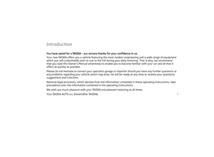 3
3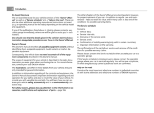 4
4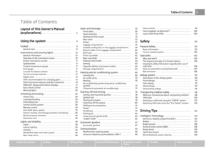 5
5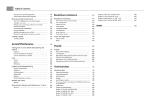 6
6 7
7 8
8 9
9 10
10 11
11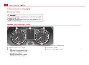 12
12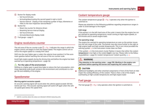 13
13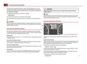 14
14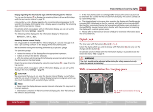 15
15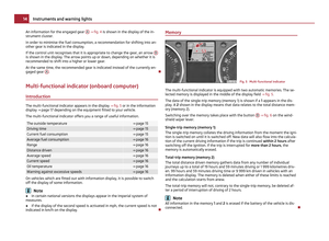 16
16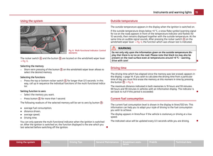 17
17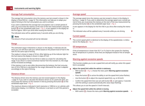 18
18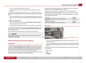 19
19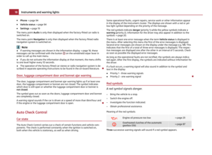 20
20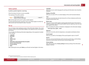 21
21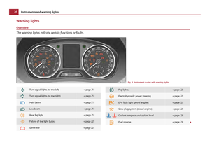 22
22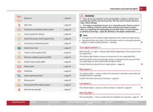 23
23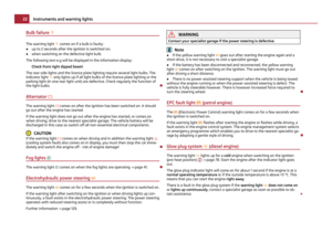 24
24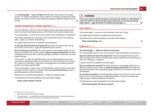 25
25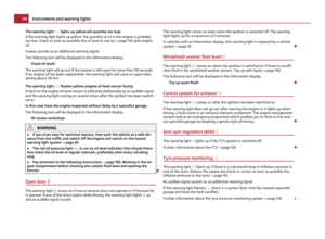 26
26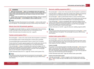 27
27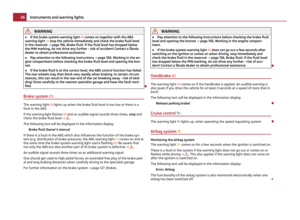 28
28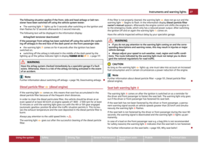 29
29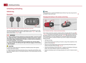 30
30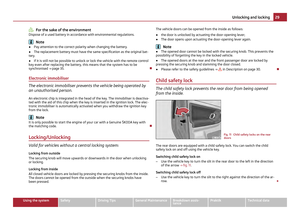 31
31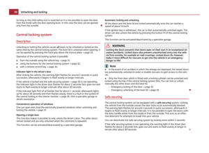 32
32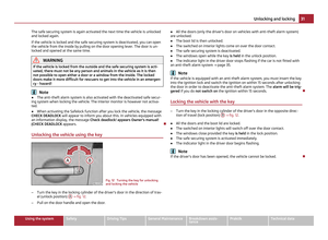 33
33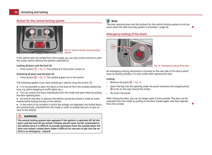 34
34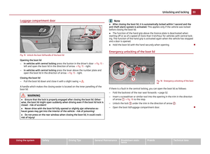 35
35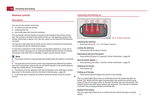 36
36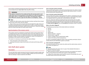 37
37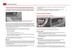 38
38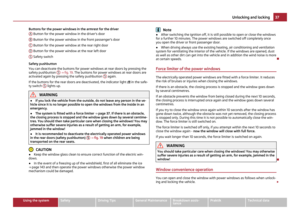 39
39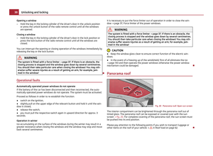 40
40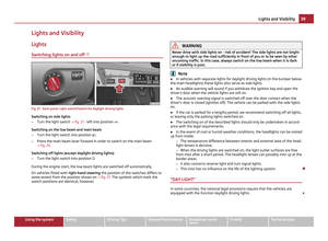 41
41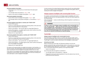 42
42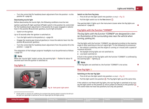 43
43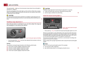 44
44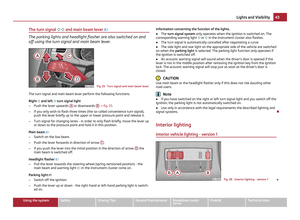 45
45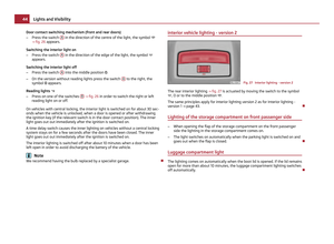 46
46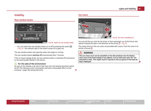 47
47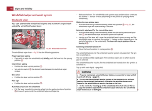 48
48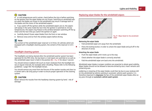 49
49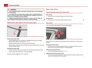 50
50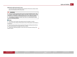 51
51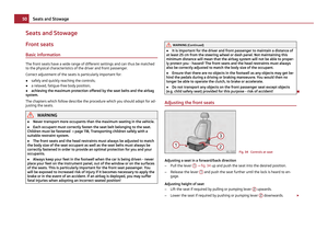 52
52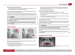 53
53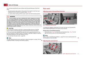 54
54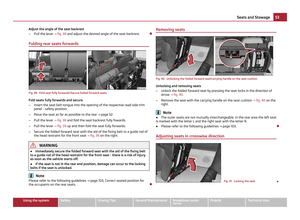 55
55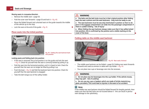 56
56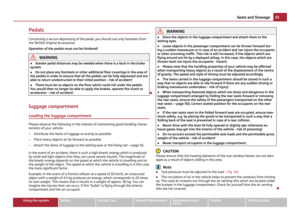 57
57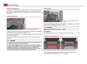 58
58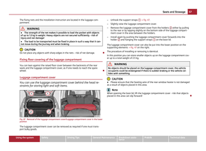 59
59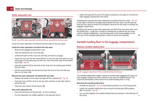 60
60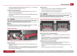 61
61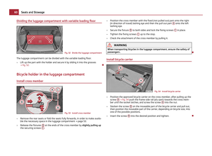 62
62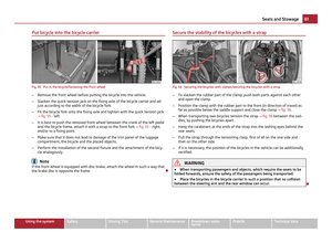 63
63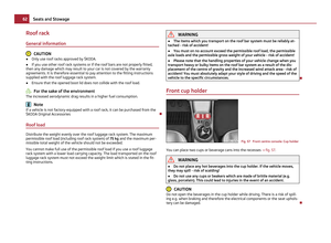 64
64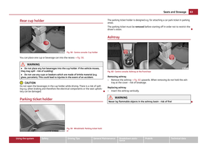 65
65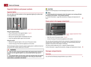 66
66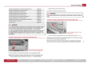 67
67 68
68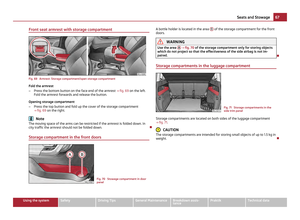 69
69 70
70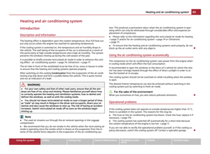 71
71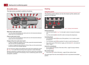 72
72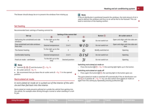 73
73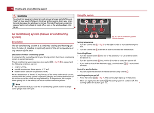 74
74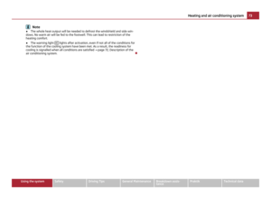 75
75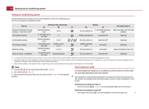 76
76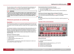 77
77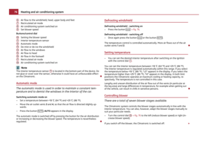 78
78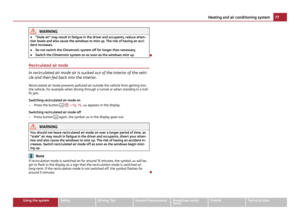 79
79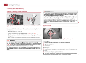 80
80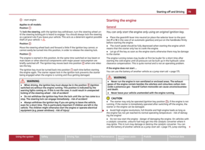 81
81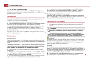 82
82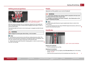 83
83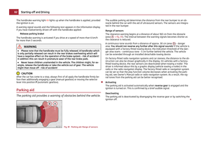 84
84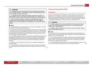 85
85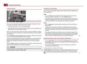 86
86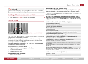 87
87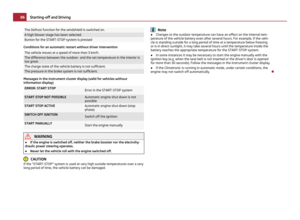 88
88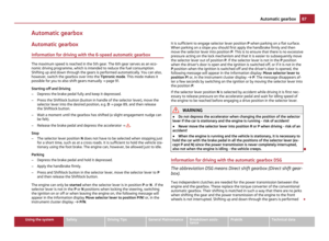 89
89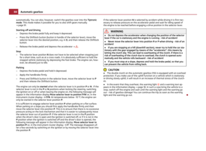 90
90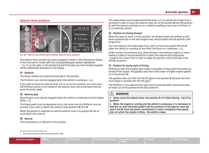 91
91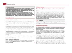 92
92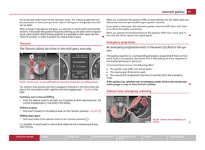 93
93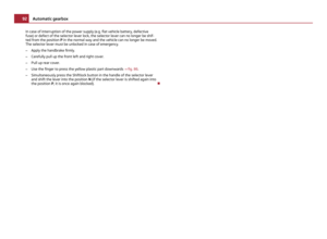 94
94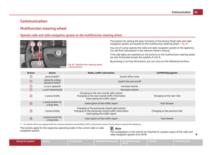 95
95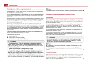 96
96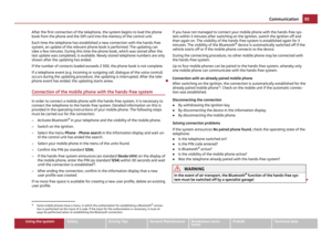 97
97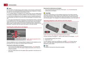 98
98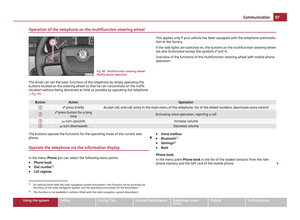 99
99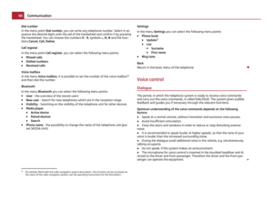 100
100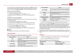 101
101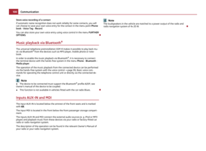 102
102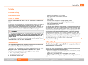 103
103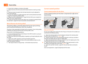 104
104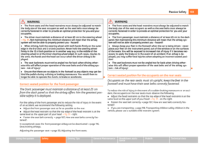 105
105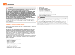 106
106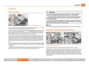 107
107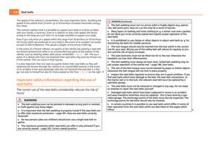 108
108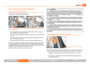 109
109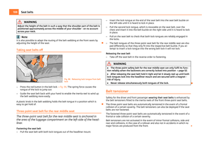 110
110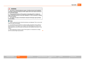 111
111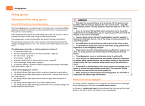 112
112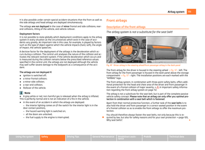 113
113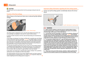 114
114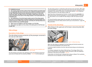 115
115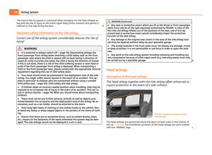 116
116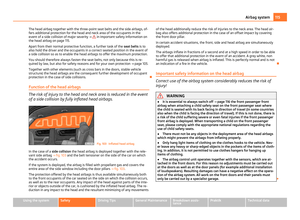 117
117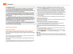 118
118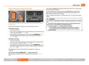 119
119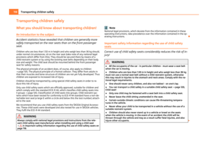 120
120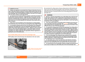 121
121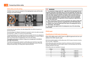 122
122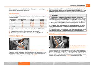 123
123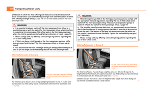 124
124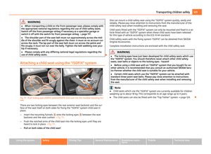 125
125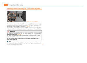 126
126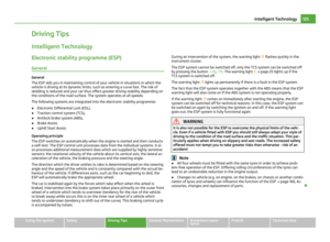 127
127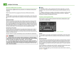 128
128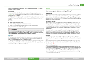 129
129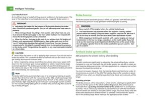 130
130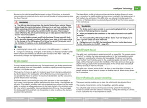 131
131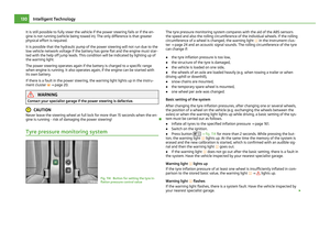 132
132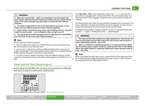 133
133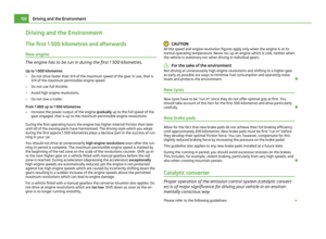 134
134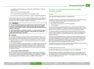 135
135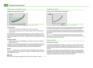 136
136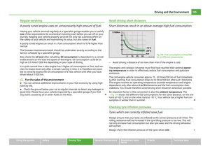 137
137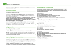 138
138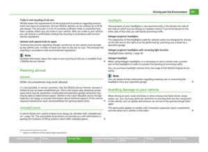 139
139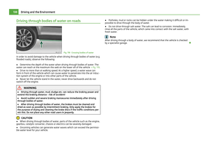 140
140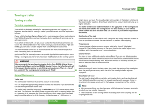 141
141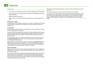 142
142 143
143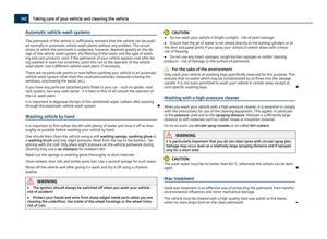 144
144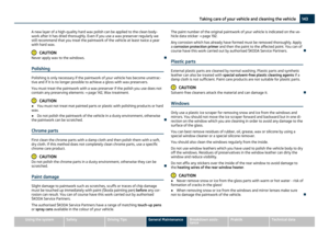 145
145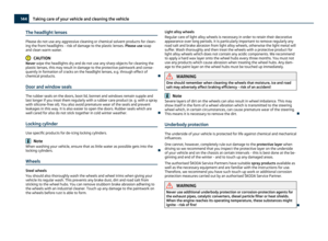 146
146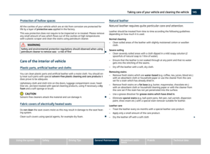 147
147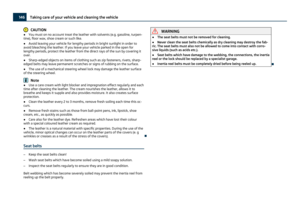 148
148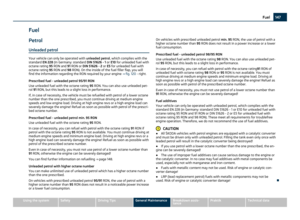 149
149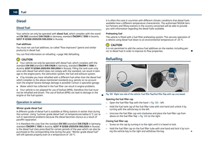 150
150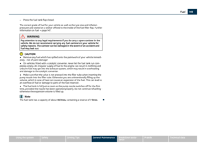 151
151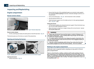 152
152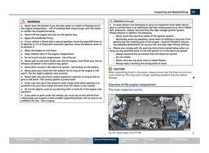 153
153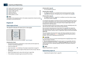 154
154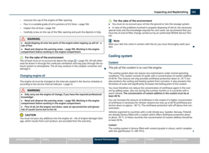 155
155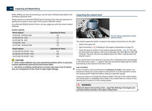 156
156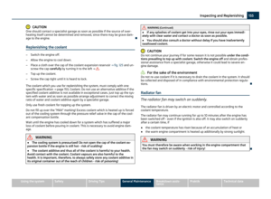 157
157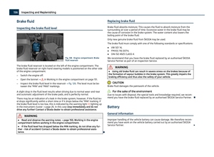 158
158 159
159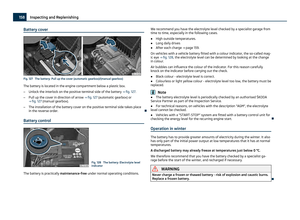 160
160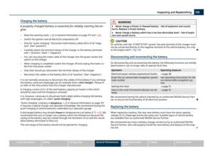 161
161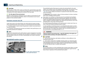 162
162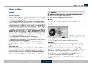 163
163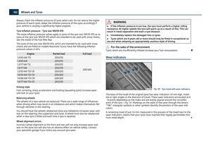 164
164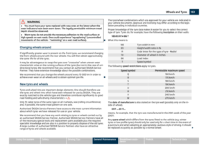 165
165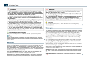 166
166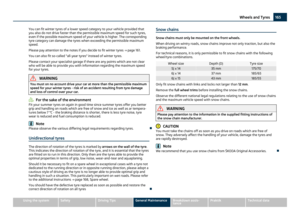 167
167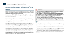 168
168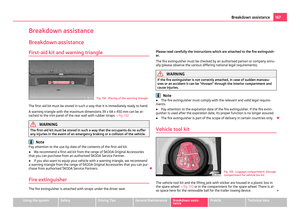 169
169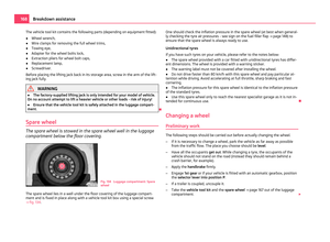 170
170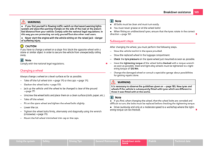 171
171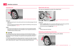 172
172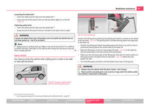 173
173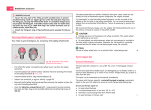 174
174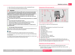 175
175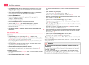 176
176 177
177 178
178 179
179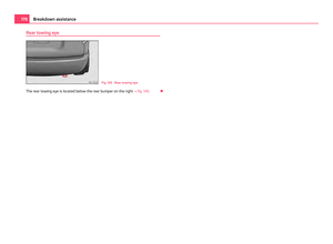 180
180 181
181 182
182 183
183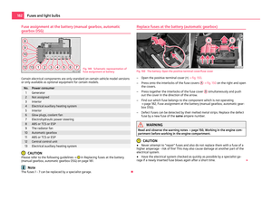 184
184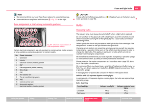 185
185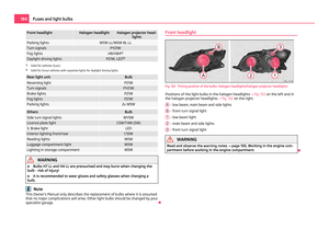 186
186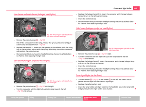 187
187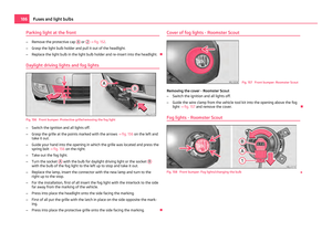 188
188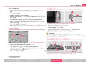 189
189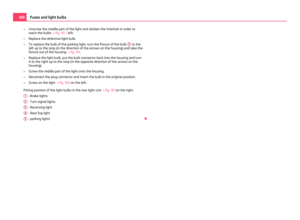 190
190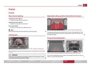 191
191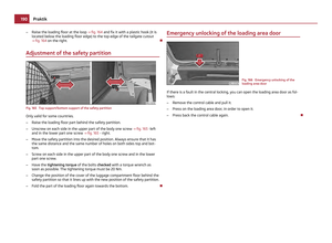 192
192 193
193 194
194 195
195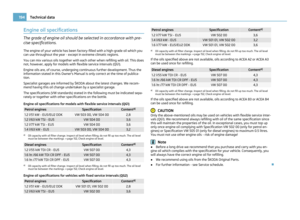 196
196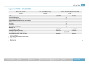 197
197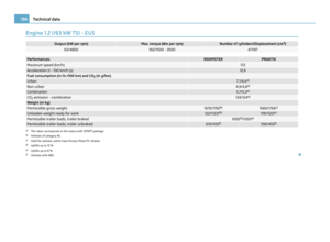 198
198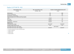 199
199 200
200 201
201 202
202 203
203 204
204 205
205 206
206 207
207 208
208 209
209 210
210 211
211