Page 153 of 236

13B-153
DIESEL INJECTION
Fault finding - Interpretation of statuses13B
V10 MR-372-J84-13B150$564.mif
EDC16 INJECTION
Program No.: C1
Vdiag No.: 44, 48 and 4C
ET015
FAN ASSEMBLY 2 CHECK
NOTESOnly perform the tests if the statuses do not correspond with the system programming
functions.
Note: Status ET015 Engine fan assembly 2 and status ET021 High-speed engine fan request change their
status at the same time.
RUNNING
The engine fan assembly can be supplied when:
– the engine coolant temperature is above 99°C.
– the injection computer has system faults that could lead to the engine overheating.
When the high speed fan is supplied:
– status ET015 changes to RUNNING
– status ET021 low-speed engine fan request changes to ACTIVE.
In the event that the high-speed engine fan does not work, refer to the UPC fault finding note.
STOPPED
The high-speed fan assembly stops when:
– the engine coolant temperature is below 99°C;
IMPORTANT!WARNING
If the UPC does not detect the injection computer frames, the low speed engine
fan is supplied until the battery is completely discharged.
In the event that the low-speed engine fan assembly is defective, the high-speed
engine fan assembly will then be activated.
AFTER REPAIRCarry out a road test followed by another check with the diagnostic tool.
EDC16_V44_ET015/EDC16_V48_ET015/EDC16_V4C_ET015
Page 154 of 236

13B-154
DIESEL INJECTION
Fault finding - Interpretation of statuses13B
V10 MR-372-J84-13B150$564.mif
EDC16 INJECTION
Program No.: C1
Vdiag No.: 44, 48 and 4C
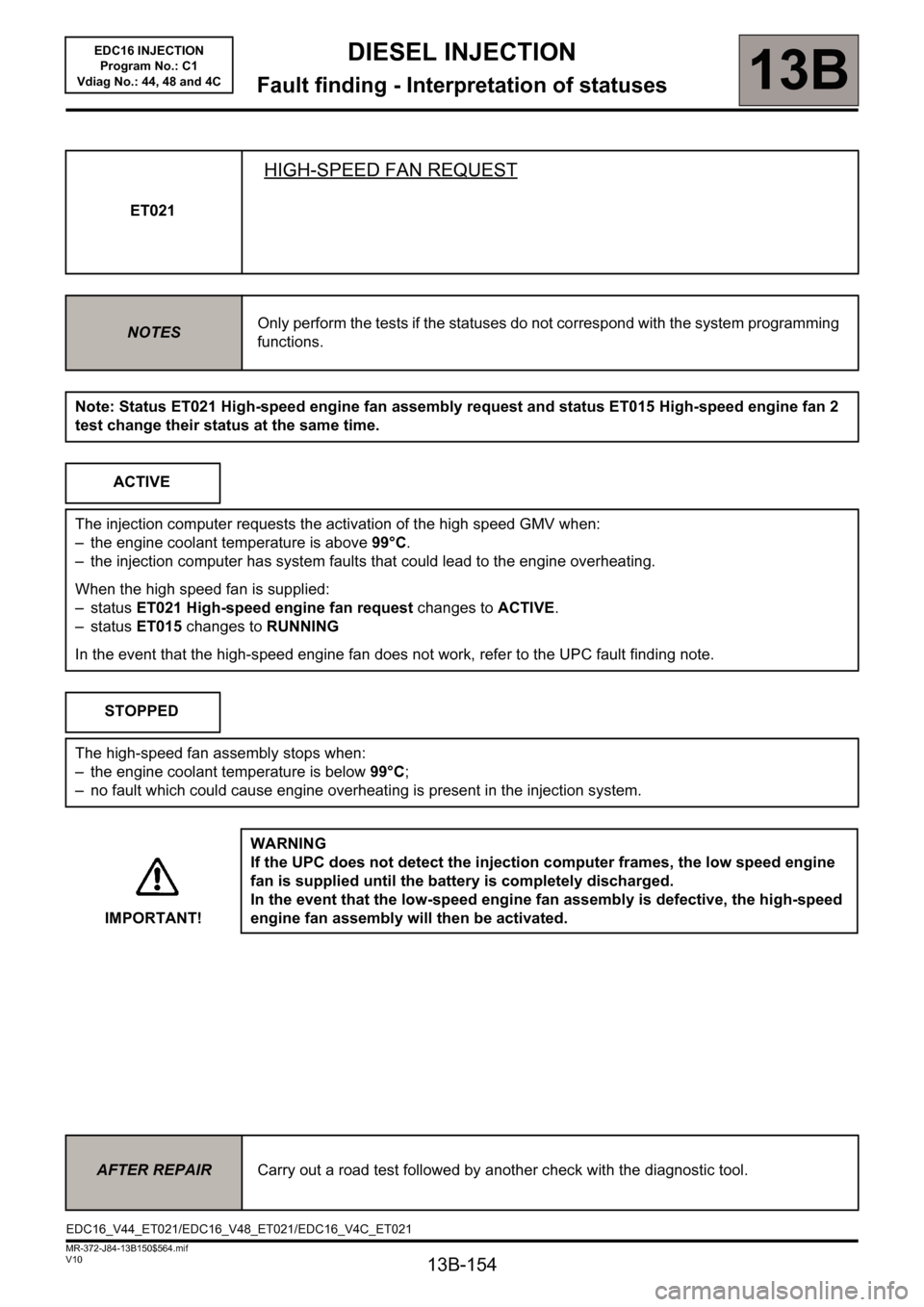
ET021
HIGH-SPEED FAN REQUEST
NOTESOnly perform the tests if the statuses do not correspond with the system programming
functions.
Note: Status ET021 High-speed engine fan assembly request and status ET015 High-speed engine fan 2
test change their status at the same time.
ACTIVE
The injection computer requests the activation of the high speed GMV when:
– the engine coolant temperature is above 99°C.
– the injection computer has system faults that could lead to the engine overheating.
When the high speed fan is supplied:
– status ET021 High-speed engine fan request changes to ACTIVE.
– status ET015 changes to RUNNING
In the event that the high-speed engine fan does not work, refer to the UPC fault finding note.
STOPPED
The high-speed fan assembly stops when:
– the engine coolant temperature is below 99°C;
– no fault which could cause engine overheating is present in the injection system.
IMPORTANT!WARNING
If the UPC does not detect the injection computer frames, the low speed engine
fan is supplied until the battery is completely discharged.
In the event that the low-speed engine fan assembly is defective, the high-speed
engine fan assembly will then be activated.
AFTER REPAIRCarry out a road test followed by another check with the diagnostic tool.
EDC16_V44_ET021/EDC16_V48_ET021/EDC16_V4C_ET021
Page 155 of 236

13B-155
DIESEL INJECTION
Fault finding - Interpretation of statuses13B
V10 MR-372-J84-13B150$564.mif
EDC16 INJECTION
Program No.: C1
Vdiag No.: 44, 48 and 4C
Note: Status ET022 Low-speed engine fan request and status ET014 Engine fan assembly check 1 change
their status at the same time.ET022
LOW-SPEED FAN REQUEST
NOTESOnly perform the tests if the statuses do not correspond with the system programming
functions.
ACTIVE
The injection computer requests the activation of the low speed GMV when:
– the engine coolant temperature is above 89°C,
– the injection computer has system faults that could lead to the engine overheating,
– the air conditioning is switched on by the driver.
When the high speed fan is supplied:
– status ET022 High-speed engine fan request changes to ACTIVE,
– status ET014 changes to RUNNING.
In the event that the low-speed engine fan does not work, refer to the UPC fault finding note.
STOPPED
The low-speed fan assembly stops when:
– the engine coolant temperature is below 89°C,
– no fault which could cause engine overheating is present in the injection system.
– the air conditioning is not switched on by the driver.
IMPORTANT!WARNING
If the UPC does not detect the injection computer frames, the low speed engine
fan is supplied until the battery is completely discharged.
In the event that the low-speed engine fan assembly is defective, the high-speed
engine fan assembly will then be activated.
AFTER REPAIRCarry out a road test followed by another check with the diagnostic tool.
EDC16_V44_ET022/EDC16_V48_ET022/EDC16_V4C_ET022
Page 156 of 236
13B-156
DIESEL INJECTION
Fault finding - Interpretation of statuses13B
V10 MR-372-J84-13B150$564.mif
EDC16 INJECTION
Program No.: C1
Vdiag No.: 44, 48 and 4C
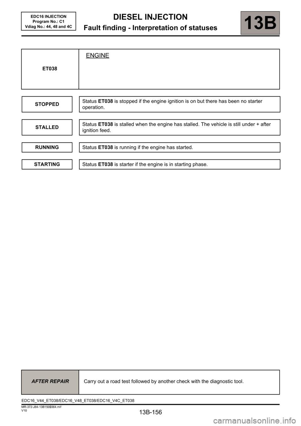
ET038
ENGINE
STOPPEDStatus ET038 is stopped if the engine ignition is on but there has been no starter
operation.
STALLEDStatus ET038 is stalled when the engine has stalled. The vehicle is still under + after
ignition feed.
RUNNINGStatus ET038 is running if the engine has started.
STARTINGStatus ET038 is starter if the engine is in starting phase.
AFTER REPAIRCarry out a road test followed by another check with the diagnostic tool.
EDC16_V44_ET038/EDC16_V48_ET038/EDC16_V4C_ET038
Page 157 of 236

DIESEL INJECTION
Fault finding - Interpretation of statuses13B
13B-157V10 MR-372-J84-13B150$564.mif
EDC16 INJECTION
Program No.: C1
Vdiag No.: 44, 48 and 4C
ET042
CRUISE CONTROL/SPEED LIMITER
STATUS DEFINITION
NOT DETECTED: This status indicates that the cruise control or speed limiter function
is not present on the vehicle.
INACTIVE: This status indicates that the cruise control/speed limiter main On/Off
switch is in the rest (or neutral) position.
SPEED LIMITER: This status indicates that the driver has used the main switch to
select the speed limiter.
CRUISE CONTROL: This status indicates that the driver has used the main switch to
select the cruise control.
NOTESSpecial notes:
Only perform these tests if the statuses do not correspond with the system
programming functions.
NOT
DETECTED
If the vehicle does not have cruise control or speed limiter function buttons, status ET042
is permanently NOT DETECTED. This confirms that the cruise control/speed limiter
function is not present on the vehicle.
If the vehicle is fitted with cruise control or speed limiter function buttons, the main switch
is in the rest (or neutral) position and the injection computer has just been programmed
or reprogrammed, then status ET042 is NOT DETECTED.
To activate the cruise control or speed limiter function, press the main switch in the cruise
control position and then in the speed limiter position.
Return to rest position
The tool displays status ET042 INACTIVE.
If not, several steps must be checked:
1 Return to the multiplex network test page on the Clip application. Repeat the multiplex
network test. Re-establish dialogue with the injection computer. Check status ET042.
If ET042 is INACTIVE, the injection computer has detected the various positions of the
main switch. The cruise control/speed limiter is activated.
2 If ET042 is NOT DETECTED, check that the owner of the vehicle has not, sometime
in the past, asked for the cruise control/speed limiter function to be deactivated.
Contact the Techline.
AFTER REPAIRDeal with any faults.
Carry out a road test followed by another check with the diagnostic tool.
EDC16_V44_ET042/EDC16_V48_ET042/EDC16_V4C_ET042
Page 158 of 236

13B-158
DIESEL INJECTION
Fault finding - Interpretation of statuses13B
V10 MR-372-J84-13B150$564.mif
EDC16 INJECTION
Program No.: C1
Vdiag No.: 44, 48 and 4C
ET042
(CONTINUED 1)
INACTIVE
When the main switch is in rest position (or neutral), status ET042 is INACTIVE.
If CRUISE CONTROL or SPEED LIMITER appears despite the main button being in the
rest position (or neutral), carry out the following operations:
Check the connections of the cruise control/speed limiter main switch.
Check for + 12 V APC on the main switch connector.
– Connection code AP43 of component 1081 (Mégane II)
– Connection code AP43 of component 1546 (Scénic II)
Disconnect the main switch and with it in the rest position, check the insulation between:
– Connection codes AP43 and 3FX of component 1081 (Mégane II)
– Connection codes AP43 and 3PD of component 1081 (Mégane II)
– Connection codes AP43 and 3FX of component 1546 (Scénic II)
– Connection codes AP43 and 3PD of component 1546 (Scénic II)
Check the continuity between connections AP43 and 3PD of component 1081
(Mégane II) and component 1546 (Scénic II) in the speed limiter position.
Check the continuity between connections AP43 and 3FX of component 1081
(Mégane II) and component 1546 (Scénic II) in the cruise control position.
If these checks are not in order, replace the switch.
Check the insulation, continuity and the absence of interference resistance on the
following connections:
– Connection code 3FX,
– Connection code3PD.
Between components 1081 and 120 (Mégane II)
Between components 1546 and 120 (Scénic II)
Also check the engine management computer connectors.
If there is a repair method (see Technical Note 6015A, Repairing electrical wiring,
Wiring: Precautions for repair), repair the wiring, otherwise replace it.
AFTER REPAIRDeal with any faults.
Carry out a road test followed by another check with the diagnostic tool.
Page 159 of 236

13B-159
DIESEL INJECTION
Fault finding - Interpretation of statuses13B
V10 MR-372-J84-13B150$564.mif
EDC16 INJECTION
Program No.: C1
Vdiag No.: 44, 48 and 4C
ET042
(CONTINUED 2)
SPEED
LIMITER
When the driver presses the main switch in the speed limiter position, status ET042
becomes SPEED LIMITER.
If CRUISE CONTROL or INACTIVE appears although the switch was depressed in the
speed limiter position, carry out the following operations:
Check the connections of the cruise control/speed limiter main switch.
Check for + 12 V after ignition on the main switch connector.
– Connection code AP43 of component 1081 (Mégane II).
– Connection code AP43 of component 1546 (Scénic II).
Disconnect the main switch and with it in the rest position, check the insulation between:
– Connection codes AP43 and 3FX of component 1081 (Mégane II).
– Connection codes AP43 and 3PD of component 1081 (Mégane II).
– Connection codes AP43 and 3FX of component 1546 (Scénic II).
– Connection codes AP43 and 3PD of component 1546 (Scénic II).
– Check the continuity between connections AP43 and 3PD of component 1081
(Mégane II) and component 1546 (Scénic II) in the speed limiter position.
– Check the continuity between connections AP43 and 3FX of component 1081
(Mégane II) and component 1546 (Scénic II) in the cruise control position.
If these checks show incorrect values, replace the main switch.
Check the insulation, continuity and the absence of interference resistance on the
following connections:
– Connection code 3FX,
– Connection code 3PD,
between components 1081 and 120 (Mégane II).
between components 1546 and 120 (Scénic II).
Also check the engine management computer connectors.
If there is a repair procedure (see Technical Note 6015A, Electrical wiring repair,
Wiring: Precautions for repair), repair the wiring, otherwise replace the wiring.
AFTER REPAIRDeal with any faults.
Carry out a road test followed by another check with the diagnostic tool.
Page 160 of 236

13B-160
DIESEL INJECTION
Fault finding - Interpretation of statuses13B
V10 MR-372-J84-13B150$564.mif
EDC16 INJECTION
Program No.: C1
Vdiag No.: 44, 48 and 4C
ET042
(CONTINUED 3)
CRUISE
CONTROL
When the driver presses the main cruise control button, status ET042 becomes CRUISE
CONTROL.
If SPEED LIMITER or INACTIVE appears although the driver pressed the switch in the
cruise control position, carry out the following operations:
Check the connections of the cruise control/speed limiter main switch.
Check for + 12 V APC on the main switch connector.
– Connection code AP43 of component 1081 (Mégane II).
– Connection code AP43 of component 1546 (Scénic II).
Disconnect the switch and when it is in the rest position, check the insulation between:
– Connection codes AP43 and 3FX of component 1081 (Mégane II).
– Connection codes AP43 and 3PD of component 1081 (Mégane II).
– Connection codes AP43 and 3FX of component 1546 (Scénic II).
– Connection codes AP43 and 3PD of component 1546 (Scénic II).
Check the continuity between connections AP43 and 3PD of component 1081
(Mégane II) or component 1546 (Scénic II) in the speed limiter position.
Check the continuity between connections AP43 and 3FX of component 1081
(Mégane II) or component 1546 (Scénic II) in the cruise control position.
If these checks show incorrect values, replace the main switch.
Check the insulation, continuity, and the absence of interference resistance on the
following connections:
– Connection code 3FX,
– Connection code3PD.
Between components 1081 and 120 (Mégane II).
Between components 1546 and 120 (Scénic II).
Also check the engine management computer connectors.
If there is a repair method (see Technical Note 6015A, Repairing electrical wiring,
Wiring: Precautions for repair), repair the wiring, otherwise replace it.
AFTER REPAIRDeal with any other faults. Clear the fault memory.
Switch off the ignition and carry out a road test followed by a test with the diagnostic
tool.