Page 97 of 236
13B-97
DIESEL INJECTION
Fault finding - Interpretation of faults
13B
V10 MR-372-J84-13B150$376.mif
EDC16 INJECTION
Program No.: C1
Vdiag No.: 44, 48 and 4C
DF209
CONTINUED 2
1.DEF
NOTESOnly in Vdiag 4C.
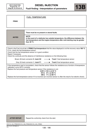
Check the EGR valve connections.
Check the injection computer connections.
Repair if necessary.
Run command RZ002 EGR Adaptives to reinitialise the valve operating values.
(See the Replacement of components section).
Check the continuity, absence of interference resistance on the following connections:
Injection computer, brown 48 track connector B track J2 Track 6 EGR valve
Injection computer brown 48-track connector B, track F4 Track 2 EGR valve
Injection computer grey 32-track connector C, track C2 Track 4 EGR valve
Repair if necessary.
If after all the checks the fault is still present, replace the EGR valve.
AFTER REPAIRDeal with any faults.
Carry out a road test, then check with the diagnostic tool.
Page 98 of 236
13B-98
DIESEL INJECTION
Fault finding - Interpretation of faults
13B
V10 MR-372-J84-13B150$376.mif
EDC16 INJECTION
Program No.: C1
Vdiag No.: 44, 48 and 4C
DF250
PRESENT
OR
STOREDELECTRONIC STABILITY PROGRAM FUNCTION
1.DEF : CAN connection fault
2.DEF : inconsistent signal
NOTESConditions for applying the fault finding procedure to a stored fault:
The fault is declared present during a road test.
Special notes:
Use bornier Ele. 1681 for all operations on the injection computer connectors.
Check the ABS computer connections.
Check the injection computer connections.
Repair if necessary.
Carry out a fault finding procedure on the multiplex network and ABS.
(See 88C, Multiplexing and 38C ABS) to deal with any faults.
If the fault is still present, contact the Techline.
AFTER REPAIRDeal with any faults.
Carry out a road test, then check with the diagnostic tool.
EDC16_V44_DF250/EDC16_V48_DF250/EDC16_V4C_DF250
Page 99 of 236

13B-99
DIESEL INJECTION
Fault finding - Interpretation of faults
13B
V10 MR-372-J84-13B150$376.mif
EDC16 INJECTION
Program No.: C1
Vdiag No.: 44, 48 and 4C
DF272
PRESENT
OR
STOREDEGR VALVE CONTROL CIRCUIT
CC.1 : short circuit to + 12 V
CC.0 : short circuit to earth
CO : open circuit
1.DEF : internal electrical fault
NOTESConditions for applying the fault finding procedure to a stored fault:
The fault is declared present following a road test or an actuator control AC002 EGR
Solenoid Valve.
Special notes:
The EGR and turbocharging functions are inhibited.
The level 1 warning light comes on.
If CC.0 is still present, the OBD warning light will come on after three consecutive
driving cycles (starting + 5 seconds + switch off the ignition and wait 40 seconds).
Use bornier Elé. 1681 for all operations on the injection computer connectors.
WARNING
If dealing with this fault requires the EGR valve to be replaced, run command RZ002 EGR Adaptives
described in Interpretation of commands in this section.
CC.1
NOTESNone.
Check the EGR valve connections.
Check the injection computer connections.
Repair if necessary.
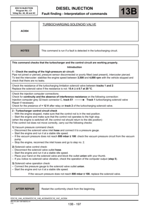
Measure the resistance of the EGR solenoid valve between tracks 1 and 5.
If the resistance is not approximately 8 Ω ±0.5 at 20°C, replace the EGR valve.
Check the continuity and insulation against + 12 V of the following connection:
Injection computer brown 48-track connector B, track L2 Track 5 of the EGR valve
Repair if necessary.
If the fault is still present, replace the EGR valve
AFTER REPAIRDeal with any faults.
Carry out a road test, then check with the diagnostic tool.
EDC16_V44_DF272/EDC16_V48_DF272/EDC16_V4C_DF272
Page 100 of 236

13B-100
DIESEL INJECTION
Fault finding - Interpretation of faults
13B
V10 MR-372-J84-13B150$376.mif
EDC16 INJECTION
Program No.: C1
Vdiag No.: 44, 48 and 4C
DF272
CONTINUED 1
CC.0
CO
NOTESSpecial notes:
If fault DF209 EGR valve position sensor circuit CO.0 is
present at the same time, check that the EGR valve
connector is properly connected.
Check the EGR valve connections.
Check the injection computer connections.
Repair if necessary.
Measure the resistance of the EGR solenoid valve between tracks 1 and 5.
If the resistance measured is not 8Ω ± 0.5 at 20°C, replace the EGR valve.
Check the continuity and insulation against earth of the following connections:
Injection computer brown 48-track connector B, track L2 Track 5 of the EGR valve
UPC black PPM1 connector track 1 Track 1 of the EGR valve
Check for + 12 V after relay (UPC) on track 1 of the EGR valve.
If there is not + 12 V on track 1, refer to the UPC fault finding note.
If the fault is still present, replace the EGR valve
AFTER REPAIRDeal with any faults.
Carry out a road test, then check with the diagnostic tool.
Page 101 of 236

13B-101
DIESEL INJECTION
Fault finding - Interpretation of faults
13B
V10 MR-372-J84-13B150$376.mif
EDC16 INJECTION
Program No.: C1
Vdiag No.: 44, 48 and 4C
DF272
CONTINUED 2
1.DEF
NOTESNone.
Check the EGR valve connections.
Check the injection computer connections.
Repair if necessary.
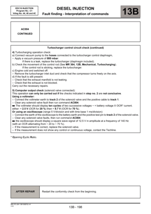
Check the resistance of the EGR solenoid valve between tracks 1 and 5.
If the resistance is not approximately 8 Ω ±0.5 at 20°C, replace the EGR valve.
Check for continuity, insulation and the absence of interference resistance on the following connections:
Injection computer brown 48-track connector B, track L2 Track 5 of the EGR valve
UPC PPM1 black connector track 1 Track 1 of the EGR valve
Check for + 12 V after relay (UPC) on track 1 of the EGR valve.
Repair if necessary.
If the fault persists, check that the computer output stage is working correctly:
– Run actuator command AC002 EGR solenoid valve.
– If there is no perceptible movement of the valve, ensure that the computer output is functioning:
– Leave the EGR valve connected.
– Connect a "wire clip" to the violet wire between the valve and the injection computer (connection
between track 6 of the valve and track J2 of the injection computer connector B).
– Connect the positive terminal of the voltmeter to the wire clip.
– Connect the negative terminal of the voltmeter to the battery earth.
– Run command AC002 EGR solenoid valve.
– The voltage should vary over 10 cycles between 1.05 V and 3.5 V.
– If the voltage varies between these values, replace the EGR valve.
– If the voltage does not vary or varies between incorrect values, contact the Techline.
AFTER REPAIRDeal with any faults.
Carry out a road test, then check with the diagnostic tool.
Page 102 of 236

13B-102
DIESEL INJECTION
Fault finding - Interpretation of faults
13B
V10 MR-372-J84-13B150$376.mif
EDC16 INJECTION
Program No.: C1
Vdiag No.: 44, 48 and 4C
DF276
PRESENT
OR
STOREDINJECTOR CODE PROGRAMMING
1.DEF : Internal electronic fault during programming
2.DEF : no code stored
NOTESConditions for applying the fault finding procedure to stored faults:
The fault is declared present after:
– replacing injector(s),
– replacing the injection computer.
Special notes:
If the fault is present:
– the engine speed is limited,
– the level 1 warning light is lit.
1.DEF
NOTESNone.
Program the injector codes using command SC002 Enter injector codes.
Carry out the procedure described in the Interpretation of commands section.
If the fault is still present, after the ignition is switched off and dialogue is established, contact the Techline.
2.DEF
NOTESThis fault appears on any blank computer (new or
recently reprogrammed).
WARNING
A computer without the IMA option can be replaced by a computer with this option. The codes are not
saved during command SC003 Save computer data.
In this case, status ET104 Injector code use changes to YES or FAULTY, fault DF276 will be present, and
the engine will operate in defect mode.
– Program the injector codes using:
command SC002 Enter injector codes, (follow the procedure described in the Interpretation of commands
section).
– After the codes have been entered:
– switch off the ignition,
– wait until power latch closes down and then switch the ignition back on,
– establish dialogue and clear the fault memory,
– end of operation.
If the fault is still present, contact the Techline.
AFTER REPAIRDeal with any faults.
Carry out a road test, then check with the diagnostic tool.
EDC16_V44_DF276/EDC16_V48_DF276/EDC16_V4C_DF276
Page 103 of 236

13B-103
DIESEL INJECTION
Fault finding - Interpretation of faults
13B
V10 MR-372-J84-13B150$376.mif
EDC16 INJECTION
Program No.: C1
Vdiag No.: 48
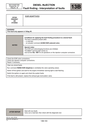
DF530
PRESENT
OR
STOREDEGR ADAPTIVES
WARNING
This fault only appears in Vdiag 48.
NOTESConditions for applying the fault finding procedure to a stored fault:
The fault is declared present after:
– a road test,
– an actuator command AC002 EGR solenoid valve.
Special notes:
The EGR and turbocharging functions are inhibited.
The level 1 warning light comes on.
Use bornier Ele. 1681 for all operations on the injection computer connectors.
Check the EGR valve connections.
Check the injection computer connections.
Repair if necessary.
Clear any stored faults.
Run command RZ002 EGR Adaptives to reinitialise the valve operating values.
Switch off the ignition and wait for the engine immobiliser warning light to start flashing.
Switch the ignition on again and check the system faults.
If the fault is still present, replace the exhaust gas recirculation valve.
AFTER REPAIRDeal with any faults.
Carry out a road test, then check with the diagnostic tool.
EDC16_V48_DF530
Page 104 of 236

13B-104
DIESEL INJECTION
Fault finding - Interpretation of faults
13B
V10 MR-372-J84-13B150$376.mif
EDC16 INJECTION
Program No.: C1
Vdiag No.: 48 and 4C
DF619
PRESENT
OR
STOREDEGR VALVE JAMMED OPEN
WARNING
This fault only appears in Vdiag 48 and 4c.
NOTESConditions for applying the fault finding procedure to a stored fault:
The fault is declared present after:
– a road test,
– an actuator command AC002 EGR solenoid valve.
Special notes:
The EGR and turbocharging functions are inhibited.
The level 1 warning light comes on.
Use bornier Ele. 1681 for all operations on the injection computer connectors.
Check the EGR valve connections.
Check the injection computer connections.
Repair if necessary.
Clear any stored faults.
Run command RZ002 EGR Adaptives to reinitialise the valve operating values.
Switch off the ignition and wait for the engine immobiliser warning light to start flashing.
Switch the ignition on again and check the system faults.
If the fault is still present:
– remove the EGR valve and reconnect it after removing it,
– check that the movement of the valve is not being blocked by a particle,
– check that the valve is not jammed or stuck in one position,
– run command AC002 EGR solenoid valve,
– check the movement of the solenoid valve,
– check that the solenoid valve is completely closed,
– if there is no movement, or if the valve is seized and cannot be repaired, replace the EGR solenoid valve.
AFTER REPAIRDeal with any faults.
Carry out a road test, then check with the diagnostic tool.
EDC16_V48_DF619/EDC16_V4C_DF619