2011 MITSUBISHI L200 fuel
[x] Cancel search: fuelPage 236 of 330
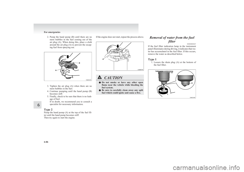
2.Pump the hand pump (B) until there are no
more bubbles in the fuel coming out of the
air plug (A). When doing this, place a cloth
around the air plug (A) to prevent the escap-
ing fuel from spraying out.
3. Tighten the air plug (A) when there are no
more bubbles in the fuel.
4. Continue pumping until the hand pump (B)
becomes stiff.
5. Finally, check to be sure that there is no leak- age of fuel.
If in doubt, we recommend you to consult a
specialist for necessary information.
Type 2
Pump the hand pump (A) at the top of the fuel fil-
ter until the hand pump becomes stiff.
Then try again to start the engine.
If the engine does not start, repeat the process above.CAUTIONl Do not smoke or have any other open
flame near the vehicle while bleeding the
fuel system.
l Be sure to carefully clean away any spilt
fuel which could ignite and cause a fire.Removal of water from the fuel
filterE00800800267
If the fuel filter indication lamp in the instrument
panel illuminates during driving, it indicates that wa-
ter has accumulated in the fuel filter. If this occurs,
remove the water as described below.
Type 1 1.Loosen the drain plug (A) at the bottom of
the fuel filter.
For emergencies
6-06
6
Page 237 of 330
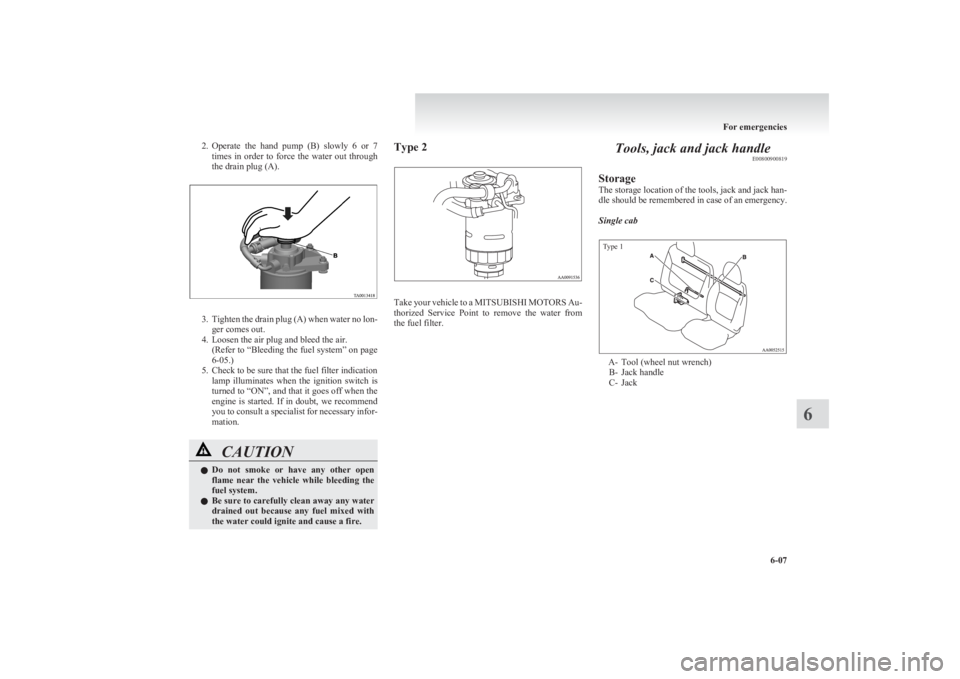
2.Operate the hand pump (B) slowly 6 or 7
times in order to force the water out through
the drain plug (A).
3. Tighten the drain plug (A) when water no lon-
ger comes out.
4. Loosen the air plug and bleed the air. (Refer to “Bleeding the fuel system” on page
6-05.)
5. Check to be sure that the fuel filter indication lamp illuminates when the ignition switch is
turned to “ON”, and that it goes off when the
engine is started. If in doubt, we recommend
you to consult a specialist for necessary infor-
mation.
CAUTIONl Do not smoke or have any other open
flame near the vehicle while bleeding the
fuel system.
l Be sure to carefully clean away any water
drained out because any fuel mixed with
the water could ignite and cause a fire.Type 2
Take your vehicle to a MITSUBISHI MOTORS Au-
thorized Service Point to remove the water from
the fuel filter.
Tools, jack and jack handle E00800900819
Storage
The storage location of the tools, jack and jack han-
dle should be remembered in case of an emergency.
Single cab
Type 1
A- Tool (wheel nut wrench) B- Jack handle
C- Jack
For emergencies
6-07
6
Page 264 of 330
Service precautionsE01000100706
Adequate care of your vehicle at regular intervals
serves to preserve the value and appearance as long
as possible.
Maintenance items as described in this owner’s man-
ual can be performed by the owner.
We recommend you to have the periodic inspection
and maintenance performed by a MITSUBISHI
MOTORS Authorized Service Point or another spe-
cialist.
In the event a malfunction or other problem is dis-
covered, we recommend you to have it checked
and repaired. This section contains information on
inspection maintenance procedures that you can do
yourself. Follow the instructions and cautions for
each of the various procedures.WARNINGl When checking or servicing the inside of
the engine compartment, make sure the
engine is switched off and has had a
chance to cool down.
l If it is necessary to do work in the engine
compartment with the engine running, be
especially careful that your clothing, hair,
etc., does not become caught by the fans,
drive belts, or other moving parts.
l For vehicle with air conditioning, the fan
may turn on automatically even if the en-
gine is not running; turn the ignition key
to “LOCK” position and remove the key
to ensure safety while you work in the en-
gine compartment.WARNINGl Do not smoke, cause sparks or allow open
flames around fuel or battery. The fumes
are flammable.
l Be extremely cautious when working
around the battery. It contains poisonous
and corrosive sulphuric acid.
l Do not get under your vehicle with just
the body jack supporting it. Always use
automotive jack stands.
l Improper handling of components and
materials used in the vehicle can endan-
ger your personal safety. We recommend
you to consult a specialist for necessary in-
formation.Catalytic converter E01000200925
For ordinary use, there are no particular precautions.
The exhaust gas scavenging devices used with the
catalytic converter are extremely efficient for the re-
duction of noxious gases. The catalytic converter is
installed in the exhaust system.
It is important to keep the engine properly tuned to
ensure proper catalyst operation and prevent possi-
ble catalyst damage.CAUTIONl Damage to the catalytic converter can re-
sult if your vehicle is not kept in proper
operating condition. In the event of an en-
gine malfunction particularly involving
engine misfire or other apparent loss of
performance, have your vehicle serviced
promptly.
Continued operation of your vehicle with
a severe overheated condition may result
in possible damage to the converter and
vehicle.WARNINGl As with any vehicle, do not park or oper-
ate this vehicle in areas where combusti-
ble materials such as dry grass or leaves
can come in contact with a hot exhaust
since a fire could occur.
l Paint should not be applied to the catalyt-
ic converter.
Maintenance
8-02
8
Page 265 of 330

The catalytic converter itself gets hot quickly, and
may be damaged if overheated. The following
points should be noted in order to prevent the igni-
tion of unburned fuel within the catalytic converter.
l Do not drive with an extremely low fuel lev-
el; running out of fuel could cause damage to
the catalytic converter.
l Do not switch OFF the ignition switch while
driving.
l Do not attempt to start the engine by pushing
the vehicle. If the battery is weak or dis-
charged, use another battery to start the en-
gine.
l Do not idle the engine for prolonged periods
during very rough idle or malfunctioning op-
erating conditions.
l Do not race the engine when turning off the
ignition switch. This will cause the catalytic
converter to be damaged due to contact with
unburnt fuel.
l Stop driving the vehicle if you think the per-
formance is noticeably low, or if the engine
has a malfunction such as with the ignition,
etc.
If it is impractical to stop driving immediate-
ly, reduce the speed and drive for only a
short time. We recommend you to have your
vehicle inspected as soon as possible.
l In unusual situations involving major engine
problems, a burnt smell may indicate severe
and abnormal catalyst overheating.
If this occurs, the vehicle should be stopped
in a safe place, the engine switched off and
the vehicle allowed to cool. Once the engine
is cool, a service, including a tune-up to man-
ufacturer’s specifications, should be obtained
immediately.Bonnet E01000302281
To open
Pull the release lever towards you to unlock the bon-
net.Raise the bonnet while pressing the safety lock.
NOTE
l Only open the bonnet when the wipers are in
the parked position. Failure to do so may
cause damage to the bonnet, wiper arms or
front windscreen.
Support the bonnet by inserting the support bar in
its slot.
Maintenance
8-03
8LHD RHD
Page 280 of 330

NOTEl Do not allow the wiper arm to fall onto the
windscreen; it could damage the glass.
3. Attach the retainers (C) to a new wiper blade.
Refer to the illustration to ensure that the re-
tainers are correctly aligned as you attach
them.
4. Insert the wiper blade into the arm, starting
with the opposite end of the blade from the
stopper. Make sure the hook (B) is fitted cor-
rectly in the grooves in the blade.
NOTE l If retainers are not supplied with the new wip-
er blade, use the retainers from the old blade.
5. Push the wiper blade until the hook (B) en-
gages securely with the stopper (A).General maintenance E01002700113
Fuel, engine coolant, oil and exhaust
gas leakage
Look under the body of your vehicle to check for
fuel, engine coolant, oil and exhaust gas leaks.WARNINGl If you see a suspicious fuel leak or if you
smell fuel, do not operate the vehicle; we
recommend you to call for assistance.
Exterior and interior lamp operation
Operate the combination lamp switch to check that
all lamps are functioning properly.
If the lamps do not illuminate, the probable cause
is a blown fuse or defective lamp bulb. Check the
fuses first. If there is no blown fuses, check the
lamp bulbs.
For information regarding the inspection and re-
placement of the fuses and the lamp bulbs, refer to
“ Fuses” on page 8-20 and “Replacement of lamp
bulbs” on page 8-23.
If the fuses and bulbs are all OK, we recommend
you to have your vehicle checked and repaired.
Meter, gauge and indicator/warning
lamps operation
Run the engine to check the operation of all meters,
gauges, and indicator/warning lamps.
If there is anything wrong, we recommend you to
have your vehicle inspected.
Maintenance
8-18
8
Page 284 of 330

Engine compartment fuse location tableE01008000583Engine compartment fuse locationFront
No.SymbolElectrical systemCa-
pacity1———2Electric window system40 A3Ignition switch40 A4Air conditioning compres-
sor10 A5Condenser fan motor20 ANo.SymbolElectrical systemCa-
pacity6Headlamp high-beam
(left)10 A7Headlamp high-beam
(right)10 A8Headlamp low beam (left)10 A9Headlamp low beam
(right)10 A10Engine control20 A11Alternator7.5 A12Stop lamps15 A13Horn10 A14Automatic transmission20 A15Hazard warning flasher10 A16Fuel pump15 A17Front fog lamps15 A18Audio amp20 A
l Some fuses may not be installed on your ve-
hicle, depending on the vehicle model or spec-
ifications.
l The table above shows the main equipment
corresponding to each fuse.
Identification of fuse E01008100308CapacityColour7.5 ABrown10 ARed15 ABlue20 AYellow30 AGreen (fuse type)/
Pink (fusible link type)40 AGreen (fusible link type)Fuse replacement E01007800656
1.Before replacing a fuse, always turn off the
electrical circuit concerned and place the ig-
nition switch in the “LOCK” position.
2. Pull the fuse lid (A) to remove it.
3. Remove the fuse puller (B) from the fuse lid
(A).
Maintenance
8-22
8 LHD
Page 297 of 330
Vehicle labeling............................................................................ 9-02
Vehicle dimensions.......................................................................9-03
Vehicle performance.....................................................................9-09
Vehicle weight .............................................................................. 9-10
Engine specifications .................................................................... 9-14
Transmission specifications .......................................................... 9-15
Electrical system ........................................................................... 9-16
Tyres and wheels .......................................................................... 9-17
Other specifications ...................................................................... 9-18
Fuel consumption ......................................................................... 9-19
Refill capacities ............................................................................ 9-21Specifications9
Page 314 of 330
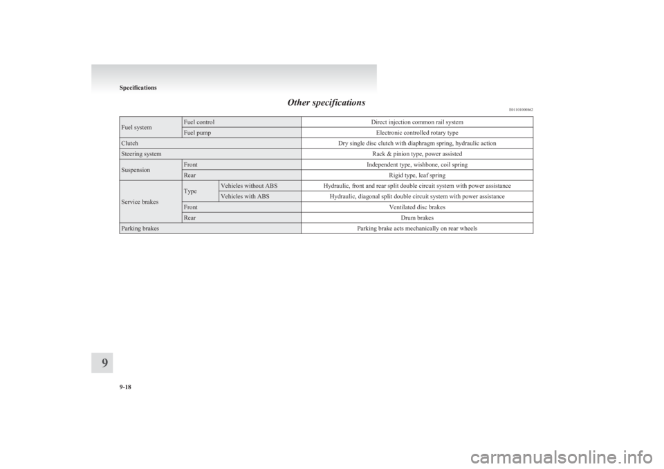
Other specificationsE01101000862Fuel systemFuel controlDirect injection common rail systemFuel pumpElectronic controlled rotary typeClutchDry single disc clutch with diaphragm spring, hydraulic actionSteering systemRack & pinion type, power assistedSuspensionFrontIndependent type, wishbone, coil springRearRigid type, leaf spring
Service brakes
TypeVehicles without ABSHydraulic, front and rear split double circuit system with power assistanceVehicles with ABSHydraulic, diagonal split double circuit system with power assistanceFrontVentilated disc brakesRearDrum brakesParking brakesParking brake acts mechanically on rear wheels
Specifications
9-18
9