2011 MITSUBISHI L200 fuel
[x] Cancel search: fuelPage 27 of 330

2.The fuel tank filler is located on the rear left
side of your vehicle.
Type 1
Open the fuel tank filler door with the re-
lease lever located below the instrument panel.3. Open the fuel tank filler tube by slowly turn-
ing the cap anticlockwise.
A- Remove B- Close
Type 2
Slide the cover (1). Insert the key in the cap
(2) and unlock it.
Turn the cap and remove it.
CAUTIONl Since the fuel system may be under pres-
sure, remove the fuel tank filler tube cap
slowly. This relieves any pressure or vac-
uum that might have built up in the fuel
tank. If you hear a hissing sound, wait un-
til it stops before removing the cap. Oth-
erwise, fuel may spray out, injuring you
or others.
4. Insert the gun in the tank port as far as it
goes. Do not tilt the gun.
5. When the gun stops automatically, do not fill
with fuel any more.
6. To close, turn the fuel tank filler tube cap
slowly clockwise until you hear clicking
sounds, then gently push the fuel tank filler
door closed.
General information
03LHD RHD
Page 28 of 330

Installation of accessoriesE00200300875
We recommend you to consult your MITSUBISHI
MOTORS Authorized Service Point.
l The installation of accessories, optional
parts, should only be carried out within the
limits prescribed by law in your country, and
in accordance with the guidelines fitting in-
structions and warnings contained within the
documents accompanying the parts or acces-
sories.
l Improper installation of electrical compo-
nents may cause an electrical fire if incorrect-
ly fitted. Please refer to the Modification/al-
teration to the electrical or fuel systems sec-
tion within this owner’s manual.
l Using a cellular phone or radio set inside the
vehicle without an external antenna may
cause electrical system interference, which
could lead to unsafe vehicle operation.
l Tyres and wheels which do not meet specifi-
cations must not be used.
Refer to the “Specifications” section for in-
formation regarding wheel and tyre sizes.
l When fitting accessories, ensure that maxi-
mum gross vehicle weight and maximum
axle weight are not exceeded.
Important points!
Due to large number of accessory and replacement
parts of different manufactures available in the mar-
ket, it is not possible, not only for MITSUBISHI
MOTORS , but also for a MITSUBISHI MOTORS
Authorized Service Point, to check whether the at-
tachment or installation of such parts affects the
overall safety of your MITSUBISHI-vehicle.
Even when such parts are officially authorized, for
example by a “general operators permit” (an ap-
praisal for the part) or through the execution of the
part in an officially approved manner of construc-
tion, or when a single operation permit following
the attachment or installation of such parts, it can-
not be deduced from that alone, that the driving safe-
ty of your vehicle has not been affected.
Consider also that there basically exists no liability
on the part of the appraiser or the official. Only in
the case of parts ( MITSUBISHI MOTORS original
replacement or exchange parts as well as
MITSUBISHI MOTORS genuine accessories) that
are recommended and released by a MITSUBISHI
MOTORS Authorized Service Point and that are at-
tached or installed by a MITSUBISHI MOTORS
Authorized Service Point can you assume, that op-
timal safety has been provided. The same also per-
tains to modifications of MITSUBISHI vehicle
with respect to the production specifications. For
your own safety, in such cases, you should only un-
dertake modifications according to the recommen-
dations of a MITSUBISHI MOTORS Authorized
Service Point.Modification/alterations to the
electrical or fuel systems E00200400238
MITSUBISHI MOTORS CORPORATION has al-
ways manufactured safe, high quality vehicles. In
order to maintain this safety and quality, it is impor-
tant that any accessory that is to be fitted, or any
modifications carried out which involve the electri-
cal or fuel systems, should be carried out in accord-
ance with MITSUBISHI guidelines.CAUTIONl If the wiring interferes with any part of
the vehicle bodywork or improper instal-
lation methods are used, i.e. protective
fuses not installed, etc.), electronic devi-
ces may be adversely affected, possibly re-
sulting in an electrical fire or other fail-
ures that may cause an accident.
General information
04
Page 88 of 330

InstrumentsE00500100876
Type AType B1- Tachometer
2- Speedometer
3- Fuel gauge4- Odometer/Tripmeter
5- Tripmeter reset button/Daytime dipper button*
6- Water temperature gauge
Instruments and controls
3-02
3
Page 90 of 330

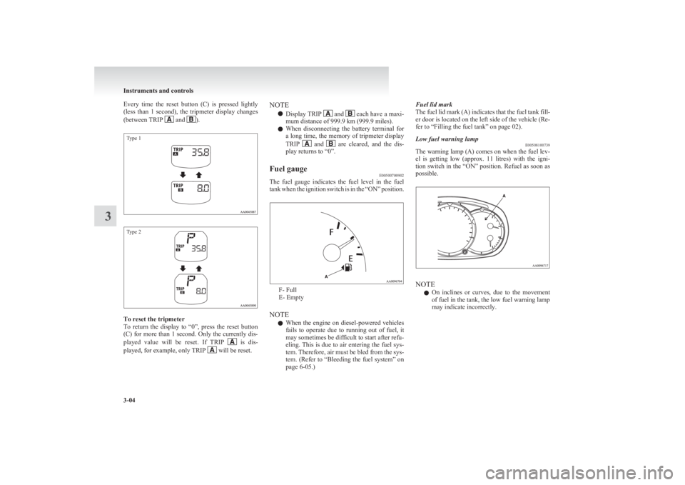
Every time the reset button (C) is pressed lightly
(less than 1 second), the tripmeter display changes
(between TRIP
and ).
Type 1Type 2
To reset the tripmeter
To return the display to “0”, press the reset button
(C) for more than 1 second. Only the currently dis-
played value will be reset. If TRIP
is dis-
played, for example, only TRIP will be reset.
NOTE
l Display TRIP
and each have a maxi-
mum distance of 999.9 km (999.9 miles).
l When disconnecting the battery terminal for
a long time, the memory of tripmeter display
TRIP
and are cleared, and the dis-
play returns to “0”.
Fuel gauge E00500700902
The fuel gauge indicates the fuel level in the fuel
tank when the ignition switch is in the “ON” position.
F- Full
E- Empty
NOTE l When the engine on diesel-powered vehicles
fails to operate due to running out of fuel, it
may sometimes be difficult to start after refu-
eling. This is due to air entering the fuel sys-
tem. Therefore, air must be bled from the sys-
tem. (Refer to “Bleeding the fuel system” on
page 6-05.)
Fuel lid mark
The fuel lid mark (A) indicates that the fuel tank fill-
er door is located on the left side of the vehicle (Re-
fer to “Filling the fuel tank” on page 02).Low fuel warning lamp E00508100739
The warning lamp (A) comes on when the fuel lev-
el is getting low (approx. 11 litres) with the igni-
tion switch in the “ON” position. Refuel as soon as
possible.
NOTE
l On inclines or curves, due to the movement
of fuel in the tank, the low fuel warning lamp
may indicate incorrectly.
Instruments and controls
3-04
3
Page 92 of 330

Indication and warning lampsE00501502002
Type 1Type 21.CRUISE indication lamp* ® p. 4-49
2. Turn-signal indication lamps/Hazard warning indication lamps ® p. 3-07
3. High-beam indication lamp ® p. 3-07
4. Front fog lamp indication lamp* ® p. 3-07
5. Rear fog lamp indication lamp ® p. 3-07
6. Seat belt reminder/warning lamp ® p. 2-10
7. Low fuel warning lamp ® p. 3-04
8. 2WD/4WD operation indication lamp* ® p. 4-27, 4-32
9. Rear differential lock indication lamp* ® p. 4-34
10. Check engine warning lamp ® p. 3-08
11. Diesel preheat indication lamp ® p. 3-07
12. Oil pressure warning lamp ® p. 3-0913.
Fuel filter indication lamp ® p. 3-07
14. Charge warning lamp ® p. 3-09
15. A/T (automatic transmission) fluid temperature warning lamp (vehicles
with A/T) ® p. 4-18
16. Overdrive off indication lamp (vehicles with 4A/T) ® p. 4-18
17. Selector lever position indicator (vehicles with A/T) ® p. 4-16, 4-23
18. Brake warning lamp ® p. 3-08
19. Active Stability & Traction Control (ASTC) OFF indication
lamp* ® p. 4-47
20. Anti-lock brake system (ABS) warning lamp* ® p. 4-44
21. Active Stability & Traction Control (ASTC) indication lamp* ® p. 4-47
22. Door ajar warning lamp ® p. 3-09
23. Supplement Restraint System (SRS) warning lamp ® p. 2-38
Instruments and controls
3-06
3
Page 93 of 330

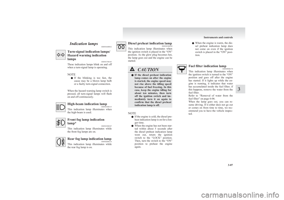
Indication lampsE00501600012Turn-signal indication lamps/
Hazard warning indication
lamps E00501700185
These indication lamps blink on and off
when a turn-signal lamp is operating.
NOTE l If the blinking is too fast, the
cause may be a blown lamp bulb
or a faulty turn-signal connection.
When the hazard warning lamp switch is
pressed, all turn-signal lamps will flash
on and off continuously.High-beam indication lamp E00501800115
This indication lamp illuminates when
the high-beam is used.Front fog lamp indication
lamp* E00501900347
This indication lamp illuminates while
the front fog lamps are on.Rear fog lamp indication lamp E00502000114
This indication lamp illuminates while
the rear fog lamp is on.Diesel preheat indication lamp E00502300250
This indication lamp illuminates when
the ignition switch is placed in the “ON”
position. As the glow plug becomes hot,
the lamp goes out and the engine can be
started.CAUTIONl If the diesel preheat indication
lamp comes on after the engine
is started, the engine speed may
not rise above the idling speed
because of fuel freezing. In this
case, keep the engine idling for
about ten minutes, then turn
off the ignition switch and im-
mediately turn it on again to
confirm that the diesel preheat
indication lamp is off.
NOTE
l If the engine is cold, the diesel pre-
heat indication lamp is on for a lon-
ger time.
l When the engine has not been star-
ted within about 5 seconds after
the diesel preheat indication lamp
went out, return the ignition
switch to the “LOCK” position.
Then, turn the switch to the “ON”
position to preheat the engine
again.
l When the engine is warm, the die-
sel preheat indication lamp does
not come on even if the ignition
switch is placed in the “ON” posi-
tion.Fuel filter indication lamp E00509900170
This indication lamp illuminates when
the ignition switch is turned to the “ON”
position and goes off after the engine
has started. If it lights up while the en-
gine is running, it indicates that water
has accumulated inside the fuel filter; if
this happens, remove the water from the
fuel filter.
Refer to “Removal of water from the
fuel filter” on page 6-06.
When the lamp goes out, you can re-
sume driving. If it either does not go out
or comes on from time to time, we rec-
ommend you to have the vehicle inspec-
ted.
Instruments and controls
3-07
3
Page 94 of 330

Warning lampsE00502400017Brake warning lamp E00502501637
This lamp illuminates when the ignition
switch is turned to the “ON” position,
and goes off after a few seconds.
Always make sure that the lamp goes off
before driving.
With the ignition switch in the “ON” po-
sition, the brake warning lamp illumi-
nates under the following conditions:
l When the parking brake lever has
been engaged.
l When the brake fluid level in the
reservoir falls to a low level.
l When the brake force distribution
function is not operating correctly.
(vehicles with anti-lock brake sys-
tem)CAUTIONl In the situations listed below,
brake performance may be com-
promised or the vehicle may be-
come unstable if brakes are ap-
plied suddenly; consequently,
avoid driving at high speeds or
applying the brakes suddenly.
Furthermore, immediately the
vehicle should be brought to a
stop in a safe location and to
have it checked.CAUTION• The brake warning lamp
does not illuminate when
the parking brake is applied
or does not turn off when
the parking brake is re-
leased.
• The ABS warning lamp and
brake warning lamp illumi-
nate at the same time.
For details, refer to “ABS
warning lamp” on page
4-44. (vehicles with anti-lock
brake system)
• The brake warning lamp re-
mains illuminated during
driving.
l The vehicle should be brought
to a halt in the following man-
ner when brake performance
has deteriorated. •Depress the brake pedal
harder than usual.
Even if the brake pedal
moves down to the very end
of its possible stroke, keep it
pressed down hard.
• Should the brakes fail, use
engine braking to reduce
your speed and carefully
pull the parking brake lever
to park your vehicle.
Depress the brake pedal to
operate the stop lamp to
alert the vehicles behind you.Check engine warning lamp E00502600657
This lamp is a part of an onboard diag-
nostic system which monitors the emis-
sions, engine and automatic transmission
control systems.
If a problem is detected in one of these
systems, this lamp illuminates.
Although your vehicle will usually be
drivable and not need towing, we recom-
mend you to have the system checked as
soon as possible.
This lamp will also illuminate for a few
seconds when the ignition switch is
turned to the “ON” position. If it does
not go off after a few seconds, we recom-
mend you to have the vehicle checked.CAUTIONl Prolonged driving with this
lamp on may cause further dam-
age to the emission control sys-
tem. It could also affect fuel
economy and drivability.
l If the lamp does not illuminate
when the ignition switch is
turned to the “ON” position,
we recommend you to have the
system checked.
Instruments and controls
3-08
3
Page 99 of 330

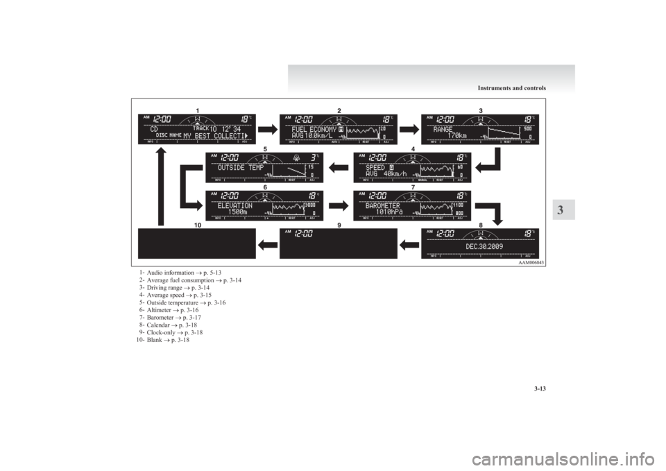
1-Audio information ® p. 5-13
2- Average fuel consumption ® p. 3-14
3- Driving range ® p. 3-14
4- Average speed ® p. 3-15
5- Outside temperature ® p. 3-16
6- Altimeter ® p. 3-16
7- Barometer ® p. 3-17
8- Calendar ® p. 3-18
9- Clock-only ® p. 3-18
10- Blank ® p. 3-18
Instruments and controls
3-13
3