2011 INFINITI QX56 check engine
[x] Cancel search: check enginePage 5003 of 5598
ST-16
< DTC/CIRCUIT DIAGNOSIS >
HEATED STEERING WHEEL SYSTEM
DTC/CIRCUIT DIAGNOSIS
HEATED STEERING WHEEL SYSTEM
Component Function CheckINFOID:0000000006225585
1.CHECK HEATED STEERING WHEEL SYSTEM
Check operate heated steering wheel system. Refer to ST-9, "
System Description (Heated Steering Wheel)".
Is the inspection result normal?
YES >> Go to ST-16, "Diagnosis Procedure".
NO >> INSPECTION END
Diagnosis ProcedureINFOID:0000000006225586
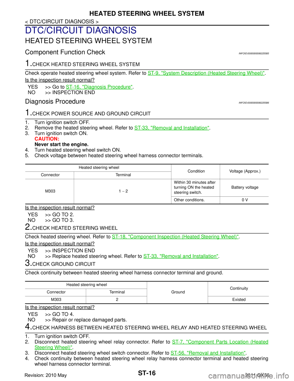
1.CHECK POWER SOURCE AND GROUND CIRCUIT
1. Turn ignition switch OFF.
2. Remove the heated steering wheel. Refer to ST-33, "
Removal and Installation".
3. Turn ignition switch ON.
CAUTION:
Never start the engine.
4. Turn heated steering wheel switch ON.
5. Check voltage between heated steering wheel harness connector terminals.
Is the inspection result normal?
YES >> GO TO 2.
NO >> GO TO 3.
2.CHECK HEATED STEERING WHEEL
Check heated steering wheel. Refer to ST-18, "
Component Inspection (Heated Steering Wheel)".
Is the inspection result normal?
YES >> INSPECTION END
NO >> Replace heated steering wheel. Refer to ST-33, "
Removal and Installation".
3.CHECK GROUND CIRCUIT
Check continuity between heated steering wheel harness connector terminal and ground.
Is the inspection result normal?
YES >> GO TO 4.
NO >> Repair or replace damaged parts.
4.CHECK HARNESS BETWEEN HEATED STEERING WHEEL RELAY AND HEATED STEERING WHEEL
1. Turn ignition switch OFF.
2. Disconnect heated steering wheel relay connector. Refer to ST-7, "
Component Parts Location (Heated
Steering Wheel)".
3. Disconnect heated steering wheel switch connector. Refer to ST-56, "
Removal and Installation".
4. Check continuity between heated steering wheel relay harness connector terminal and heated steering
wheel harness connector terminal.
Heated steering wheel Condition Voltage (Approx.)
Connector Terminal
M303 1 − 2 Within 30 minutes after
turning ON the heated
steering switch.
Battery voltage
Other conditions. 0 V
Heated steering wheel GroundContinuity
Connector Terminal
M303 2 Existed
Revision: 2010 May2011 QX56
Page 5007 of 5598
ST-20
< DTC/CIRCUIT DIAGNOSIS >
HEATED STEERING WHEEL SWITCH INDICATOR LAMP
HEATED STEERING WHEEL SWITCH INDICATOR LAMP
Component Function CheckINFOID:0000000006225589
1.CHECK HEATED STEERING WHEEL INDICATOR LAMP
1. Turn ignition switch ON.
2. Turn heated steering wheel switch ON.
Does heated steering wheel indicator lamp turn on the lamp?
YES >> GO TO 2.
NO >> Go to ST-20, "
Diagnosis Procedure".
2.CHECK HEATED STEERING WHEEL INDICATOR LAMP
Turn heated steering wheel switch OFF.
Does heated steering wheel indicator lamp turn off the lamp?
YES >> INSPECTION END
NO >> Go to ST-20, "
Diagnosis Procedure".
Diagnosis ProcedureINFOID:0000000006225590
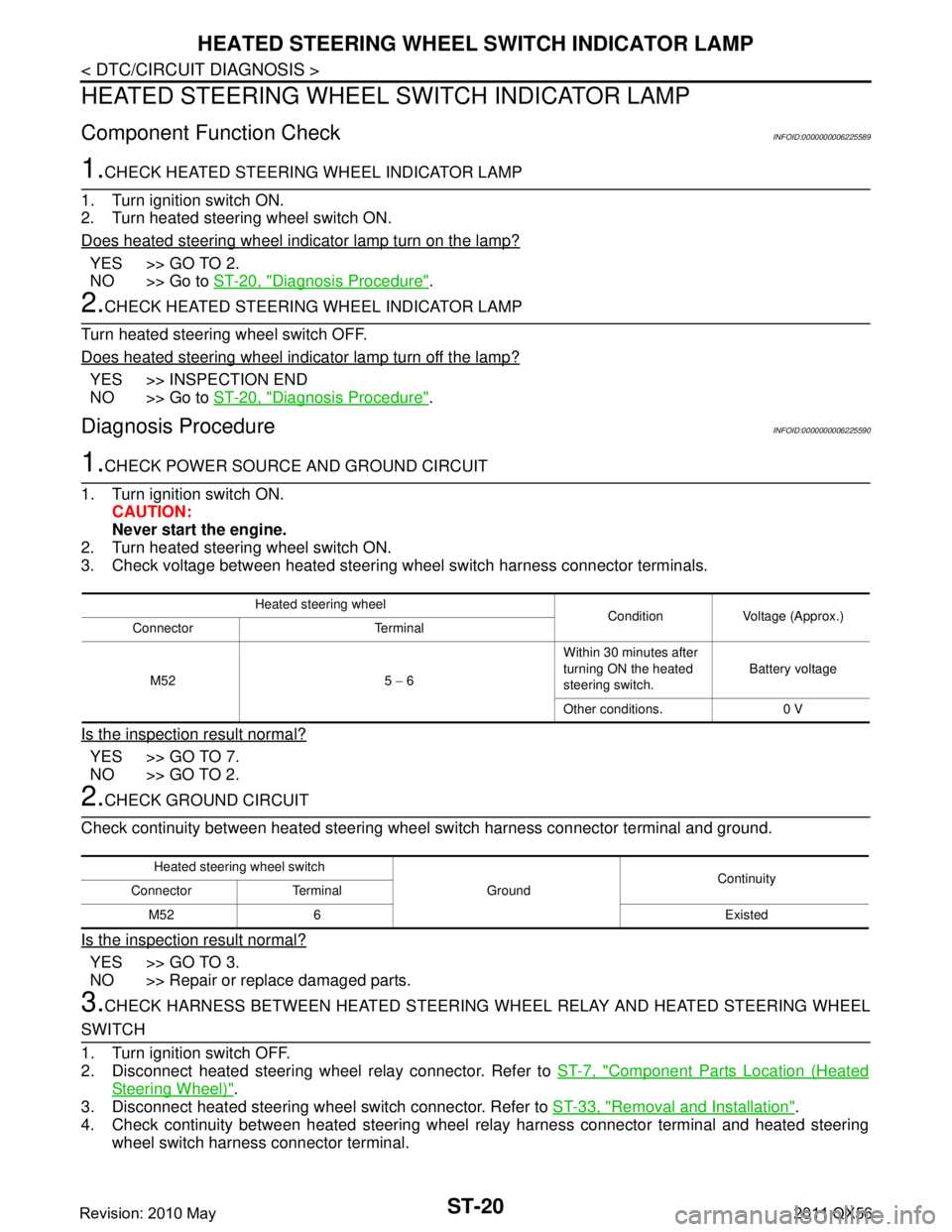
1.CHECK POWER SOURCE AND GROUND CIRCUIT
1. Turn ignition switch ON. CAUTION:
Never start the engine.
2. Turn heated steering wheel switch ON.
3. Check voltage between heated steering wheel switch harness connector terminals.
Is the inspection result normal?
YES >> GO TO 7.
NO >> GO TO 2.
2.CHECK GROUND CIRCUIT
Check continuity between heated steering wheel switch harness connector terminal and ground.
Is the inspection result normal?
YES >> GO TO 3.
NO >> Repair or replace damaged parts.
3.CHECK HARNESS BETWEEN HEATED STEERING WHEEL RELAY AND HEATED STEERING WHEEL
SWITCH
1. Turn ignition switch OFF.
2. Disconnect heated steering wheel relay connector. Refer to ST-7, "
Component Parts Location (Heated
Steering Wheel)".
3. Disconnect heated steering wheel switch connector. Refer to ST-33, "
Removal and Installation".
4. Check continuity between heated steering wheel relay harness connector terminal and heated steering
wheel switch harness connector terminal.
Heated steering wheel Condition Voltage (Approx.)
Connector Terminal
M52 5 − 6 Within 30 minutes after
turning ON the heated
steering switch.
Battery voltage
Other conditions. 0 V
Heated steering wheel switch GroundContinuity
Connector Terminal
M52 6 Existed
Revision: 2010 May2011 QX56
Page 5010 of 5598
HEATED STEERING WHEEL SYSTEM DOES NOT ACTIVATE
ST-23
< SYMPTOM DIAGNOSIS >
C
D E
F
H I
J
K L
M A
B
ST
N
O P
SYMPTOM DIAGNOSIS
HEATED STEERING WHEEL SYSTEM DOES NOT ACTIVATE
Description INFOID:0000000006225592
The heated steering wheel does not warm up.
The heated steering wheel system cannot be turned OFF.
Diagnosis ProcedureINFOID:0000000006225593
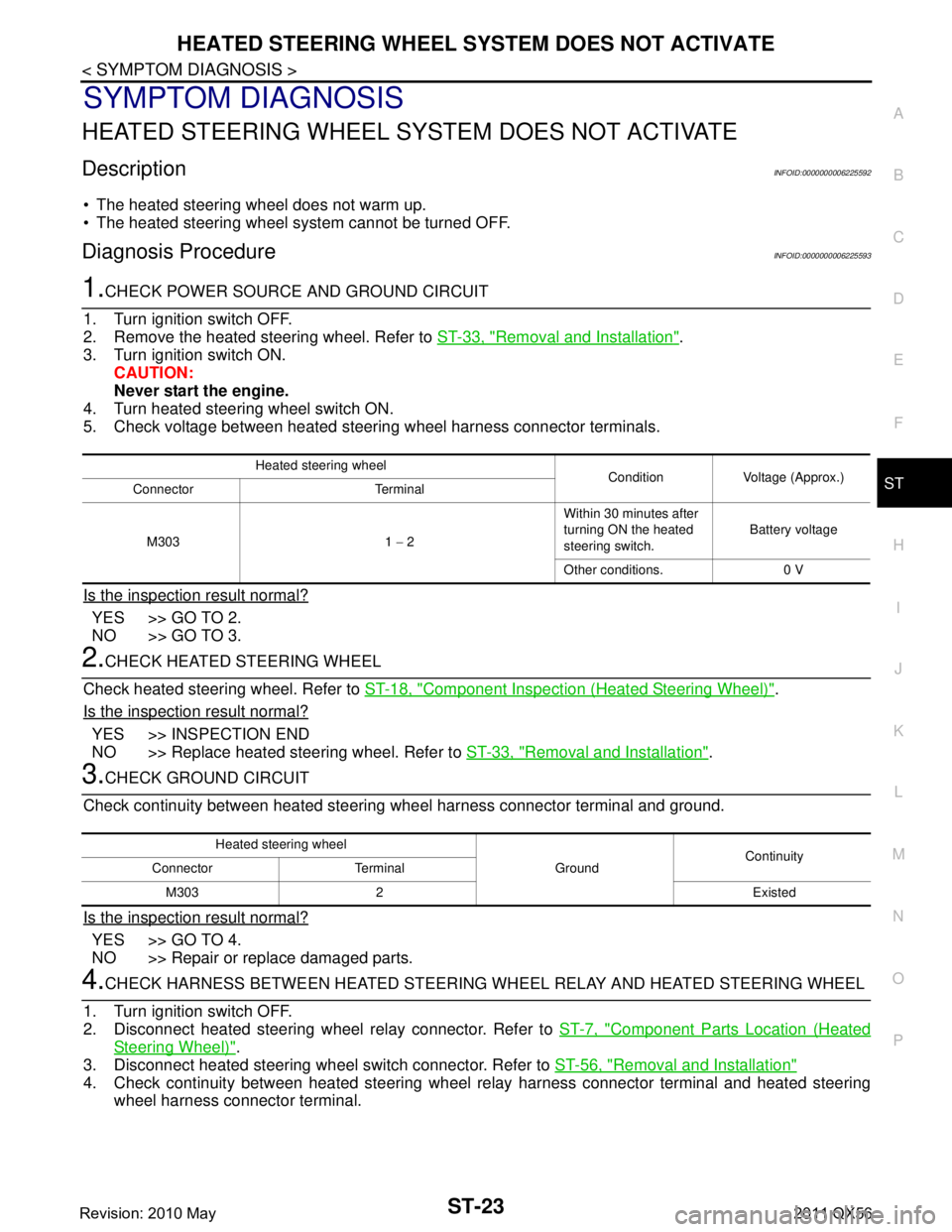
1.CHECK POWER SOURCE AND GROUND CIRCUIT
1. Turn ignition switch OFF.
2. Remove the heated steering wheel. Refer to ST-33, "
Removal and Installation".
3. Turn ignition switch ON.
CAUTION:
Never start the engine.
4. Turn heated steering wheel switch ON.
5. Check voltage between heated steering wheel harness connector terminals.
Is the inspection result normal?
YES >> GO TO 2.
NO >> GO TO 3.
2.CHECK HEATED STEERING WHEEL
Check heated steering wheel. Refer to ST-18, "
Component Inspection (Heated Steering Wheel)".
Is the inspection result normal?
YES >> INSPECTION END
NO >> Replace heated steering wheel. Refer to ST-33, "
Removal and Installation".
3.CHECK GROUND CIRCUIT
Check continuity between heated steering wheel harness connector terminal and ground.
Is the inspection result normal?
YES >> GO TO 4.
NO >> Repair or replace damaged parts.
4.CHECK HARNESS BETWEEN HEATED STEERING WHEEL RELAY AND HEATED STEERING WHEEL
1. Turn ignition switch OFF.
2. Disconnect heated steering wheel relay connector. Refer to ST-7, "
Component Parts Location (Heated
Steering Wheel)".
3. Disconnect heated steering wheel switch connector. Refer to ST-56, "
Removal and Installation"
4. Check continuity between heated steering wheel relay harness connector terminal and heated steering
wheel harness connector terminal.
Heated steering wheel Condition Voltage (Approx.)
Connector Terminal
M303 1 − 2 Within 30 minutes after
turning ON the heated
steering switch.
Battery voltage
Other conditions. 0 V
Heated steering wheel GroundContinuity
Connector Terminal
M303 2 Existed
Revision: 2010 May2011 QX56
Page 5013 of 5598
ST-26
< SYMPTOM DIAGNOSIS >
HEATED STEERING WHEEL SWITCH INDICATOR LAMP DOES NOT TURN ON
HEATED STEERING WHEEL SWITCH INDICATOR LAMP DOES NOT
TURN ON
Description INFOID:0000000006225594
Heated steering wheel switch indicator lamp does not turn on the lamp.
Heated steering wheel switch indicator lamp does not turn off the lamp.
Diagnosis ProcedureINFOID:0000000006225595
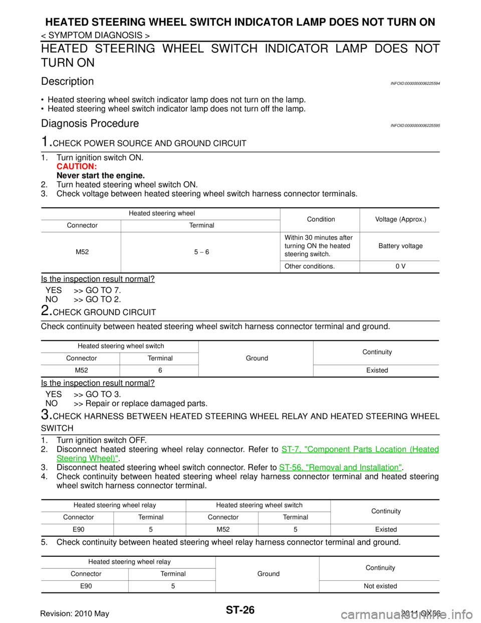
1.CHECK POWER SOURCE AND GROUND CIRCUIT
1. Turn ignition switch ON. CAUTION:
Never start the engine.
2. Turn heated steering wheel switch ON.
3. Check voltage between heated steering wheel switch harness connector terminals.
Is the inspection result normal?
YES >> GO TO 7.
NO >> GO TO 2.
2.CHECK GROUND CIRCUIT
Check continuity between heated steering wheel switch harness connector terminal and ground.
Is the inspection result normal?
YES >> GO TO 3.
NO >> Repair or replace damaged parts.
3.CHECK HARNESS BETWEEN HEATED STEERING WHEEL RELAY AND HEATED STEERING WHEEL
SWITCH
1. Turn ignition switch OFF.
2. Disconnect heated steering wheel relay connector. Refer to ST-7, "
Component Parts Location (Heated
Steering Wheel)".
3. Disconnect heated steering wheel switch connector. Refer to ST-56, "
Removal and Installation".
4. Check continuity between heated steering wheel relay harness connector terminal and heated steering
wheel switch harness connector terminal.
5. Check continuity between heated steering w heel relay harness connector terminal and ground.
Heated steering wheel
Condition Voltage (Approx.)
Connector Terminal
M52 5 − 6 Within 30 minutes after
turning ON the heated
steering switch.
Battery voltage
Other conditions. 0 V
Heated steering wheel switch GroundContinuity
Connector Terminal
M52 6 Existed
Heated steering wheel relay Heated steering wheel switch Continuity
Connector Terminal Connector Terminal
E90 5 M52 5 Existed
Heated steering wheel relay GroundContinuity
Connector Terminal
E90 5 Not existed
Revision: 2010 May2011 QX56
Page 5017 of 5598
ST-30
< PERIODIC MAINTENANCE >
POWER STEERING FLUID
PERIODIC MAINTENANCE
POWER STEERING FLUID
InspectionINFOID:0000000006225597
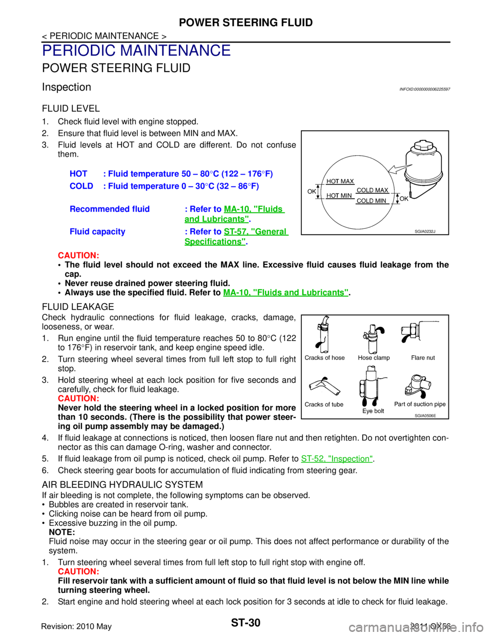
FLUID LEVEL
1. Check fluid level with engine stopped.
2. Ensure that fluid level is between MIN and MAX.
3. Fluid levels at HOT and COLD are different. Do not confuse
them.
CAUTION:
The fluid level should not exceed the MAX line. Excessive flui d causes fluid leakage from the
cap.
Never reuse drained power steering fluid.
Always use the specified fluid. Refer to MA-10, "
Fluids and Lubricants".
FLUID LEAKAGE
Check hydraulic connections for fluid leakage, cracks, damage,
looseness, or wear.
1. Run engine until the fluid temperature reaches 50 to 80 °C (122
to 176 °F) in reservoir tank, and keep engine speed idle.
2. Turn steering wheel several times from full left stop to full right stop.
3. Hold steering wheel at each lock position for five seconds and carefully, check for fluid leakage.
CAUTION:
Never hold the steering wheel in a locked position for more
than 10 seconds. (There is the possibility that power steer-
ing oil pump assembly may be damaged.)
4. If fluid leakage at connections is noticed, then loos en flare nut and then retighten. Do not overtighten con-
nector as this can damage O-ring, washer and connector.
5. If fluid leakage from oil pump is noticed, check oil pump. Refer to ST-52, "
Inspection".
6. Check steering gear boots for accumulation of fluid indicating from steering gear.
AIR BLEEDING HYDRAULIC SYSTEM
If air bleeding is not complete, the following symptoms can be observed.
Bubbles are created in reservoir tank.
Clicking noise can be heard from oil pump.
Excessive buzzing in the oil pump. NOTE:
Fluid noise may occur in the steering gear or oil pump. This does not affect performance or durability of the
system.
1. Turn steering wheel several times from full left stop to full right stop with engine off. CAUTION:
Fill reservoir tank with a sufficien t amount of fluid so that fluid level is not below the MIN line while
turning steering wheel.
2. Start engine and hold steering wheel at each lock position for 3 seconds at idle to check for fluid leakage.
HOT : Fluid temperature 50 – 80
°C (122 – 176 °F)
COLD : Fluid temperature 0 – 30 °C (32 – 86 °F)
Recommended fluid : Refer to MA-10, "
Fluids
and Lubricants".
Fluid capacity : Refer to ST-57, "
General
Specifications".
SGIA0232J
SGIA0506E
Revision: 2010 May2011 QX56
Page 5018 of 5598

POWER STEERING FLUIDST-31
< PERIODIC MAINTENANCE >
C
DE
F
H I
J
K L
M A
B
ST
N
O P
3. Repeat step 2 above several times at approximately 3 seconds intervals. CAUTION:
Never hold the steering wheel in a locked positio n for more than 10 seconds. (There is the possi-
bility that oil pump may be damaged.)
4. Check fluid for bubbles and while contamination.
5. Stop engine if bubbles and white contamination do not drain out. Perform step 2 and 3 above after waiting
until bubbles and white contamination drain out.
6. Stop the engine, and then check fluid level.
Revision: 2010 May2011 QX56
Page 5019 of 5598

ST-32
< PERIODIC MAINTENANCE >
STEERING WHEEL
STEERING WHEEL
InspectionINFOID:0000000006225598
STEERING WHEEL AXIAL END PLAY
1. Check installation conditions of steering gear assembly, front suspension assembly, axle and steering col-
umn assembly.
2. Check if movement exists when steering wheel is moved up and down, to the left and right and to the axial direction.
3. Check the following items when steering w heel axial end play is out of the standard.
Check the steering column assembly mounting condition. Refer to ST-34, "
Exploded View".
Check steering gear assembly mounting condition for looseness. Refer to ST-41, "
Exploded View".
STEERING WHEEL PLAY
1. Turn steering wheel so that front wheels come to the straight-ahead position.
2. Start engine and lightly turn steering wheel to the left and right until front wheels start to move.
3. Measure steering wheel movement on the outer circumference.
4. Check the following items when steeri ng wheel play is out of the standard.
Check backlash for each joint of steering column assembly.
Check installation condition of steering gear assembly. Steering wheel axial end play : Refer to
ST-57, "
Steering Wheel Axial End Play and Play".
Steering wheel play : Refer to ST-57, "
Steering Wheel Axial End Play and Play".
Revision: 2010 May2011 QX56
Page 5040 of 5598
![INFINITI QX56 2011 Factory Service Manual
POWER STEERING OIL PUMPST-53
< REMOVAL AND INSTALLATION >
C
DE
F
H I
J
K L
M A
B
ST
N
O P
1. Connect the oil pressure gauge [SST: KV48103500 (J-26357)] and the oil pressure gauge adapter [SST: KV4810 INFINITI QX56 2011 Factory Service Manual
POWER STEERING OIL PUMPST-53
< REMOVAL AND INSTALLATION >
C
DE
F
H I
J
K L
M A
B
ST
N
O P
1. Connect the oil pressure gauge [SST: KV48103500 (J-26357)] and the oil pressure gauge adapter [SST: KV4810](/manual-img/42/57033/w960_57033-5039.png)
POWER STEERING OIL PUMPST-53
< REMOVAL AND INSTALLATION >
C
DE
F
H I
J
K L
M A
B
ST
N
O P
1. Connect the oil pressure gauge [SST: KV48103500 (J-26357)] and the oil pressure gauge adapter [SST: KV48102500 (J-
33914)] between oil pump discharge connector and high-pres-
sure hose. Bleed air from the hydraulic circuit while opening
valve fully. Refer to ST-30, "
Inspection".
2. Start engine. Run engine until oil temperature reaches 50 to 80°C (122 to 176 °F).
CAUTION:
Leave the valve of the oil pressure gauge fully open while
starting and running engine. If engine is started with the
valve closed, the hydraulic pressure in oil pump goes up
to the relief pressure along with unusual increase of oil
temperature.
Be sure to keep hose clear of belts and other parts when engine is started.
3. Fully close the oil pressure gauge valve with engine at idle and measure the relief oil pressure.
CAUTION:
Never keep valve closed for 10 seconds or longer.
4. Open the valve slowly after measuring. Repair oil pump if the relief oil pressure is outside the standard. Refer to ST-50, "
Disassembly and Assembly".
5. Disconnect the oil pressure gauge from hydraulic circuit.
6. When installing eye bolt (1) and copper washer (2) to oil pump (3), refer to the figure.
CAUTION:
Never reuse copper washers.
Apply power steering fluid to around copper washer, theninstall eye bolt.
Install eye bolt with eye join t (assembled to high pressure
hose) (B) protrusion (A) facing with pump side cutout, and
then tighten it to the specifi ed torque after tightening by
hand. Refer to ST-54, "
Exploded View".
Securely insert harness connector to pressure sensor.
7. Check fluid level, fluid leakage and air bleeding hydraulic sys- tem after the installation. Refer to ST-30, "
Inspection".
Relief oil pressure : Refer to
ST-58, "
Relief Oil Pres-
sure".
SGIA1225E
JSGIA0452ZZ
Revision: 2010 May2011 QX56