2011 INFINITI QX56 check engine
[x] Cancel search: check enginePage 5501 of 5598

POWER SUPPLY AND GROUND CIRCUITWT-51
< DTC/CIRCUIT DIAGNOSIS >
C
DF
G H
I
J
K L
M A
B
WT
N
O P
POWER SUPPLY AND GROUND CIRCUIT
Diagnosis ProcedureINFOID:0000000006225530
1.CHECK FUSE/FUSIBLE LINK
1. Turn the ignition switch OFF.
2. Check for fusing of the fuse and fusible link at the low tire pressure warning control unit.
- Check the 10 A fuse [No. 3 in fuse block (J/B)]
Is the inspection result normal?
YES >> GO TO 2.
NO >> Repair or replace error-detected parts.
2.CHECK LOW TIRE PRESSURE WARNING CONTROL UNIT POWER SUPPLY CIRCUIT
1. Disconnect the low tire pressure warning control unit harness connector.
2. Turn the ignition switch ON. CAUTION:
Never start engine.
3. Check the voltage between the low tire pressure warning control unit and ground.
4. Turn the ignition switch OFF.
5. Check the voltage between the low tire pressure warning control unit and ground.
Is the inspection result normal?
YES >> GO TO 3.
NO >> Check the following. If any items are damaged, repair or replace damaged parts. Harness for short or open between ignition switch and low tire pressure warning control unit har-ness connector
Battery voltage.
3.CHECK LOW TIRE PRESSURE WARNI NG CONTROL UNIT GROUND CIRCUIT
1. Turn the ignition switch OFF.
2. Check the continuity between the low tire pressure warning control unit harness connector and ground.
- Also check harness for short to ground and short to power.
Is the inspection result normal?
YES >> INSPECTION END
NO >> Repair open circuit or short to ground or short to power in harness or connectors.
Low tire pressure warning control unit —Voltage
Connector Terminal
M96 15 Ground Battery voltage
Low tire pressure warning control unit —Voltage
Connector Terminal
M96 15 Ground 0 V
Low tire pressure warning control unit —Continuity
Connector Terminal
M96 32 Ground Existed
Revision: 2010 May2011 QX56
Page 5502 of 5598

WT-52
< DTC/CIRCUIT DIAGNOSIS >
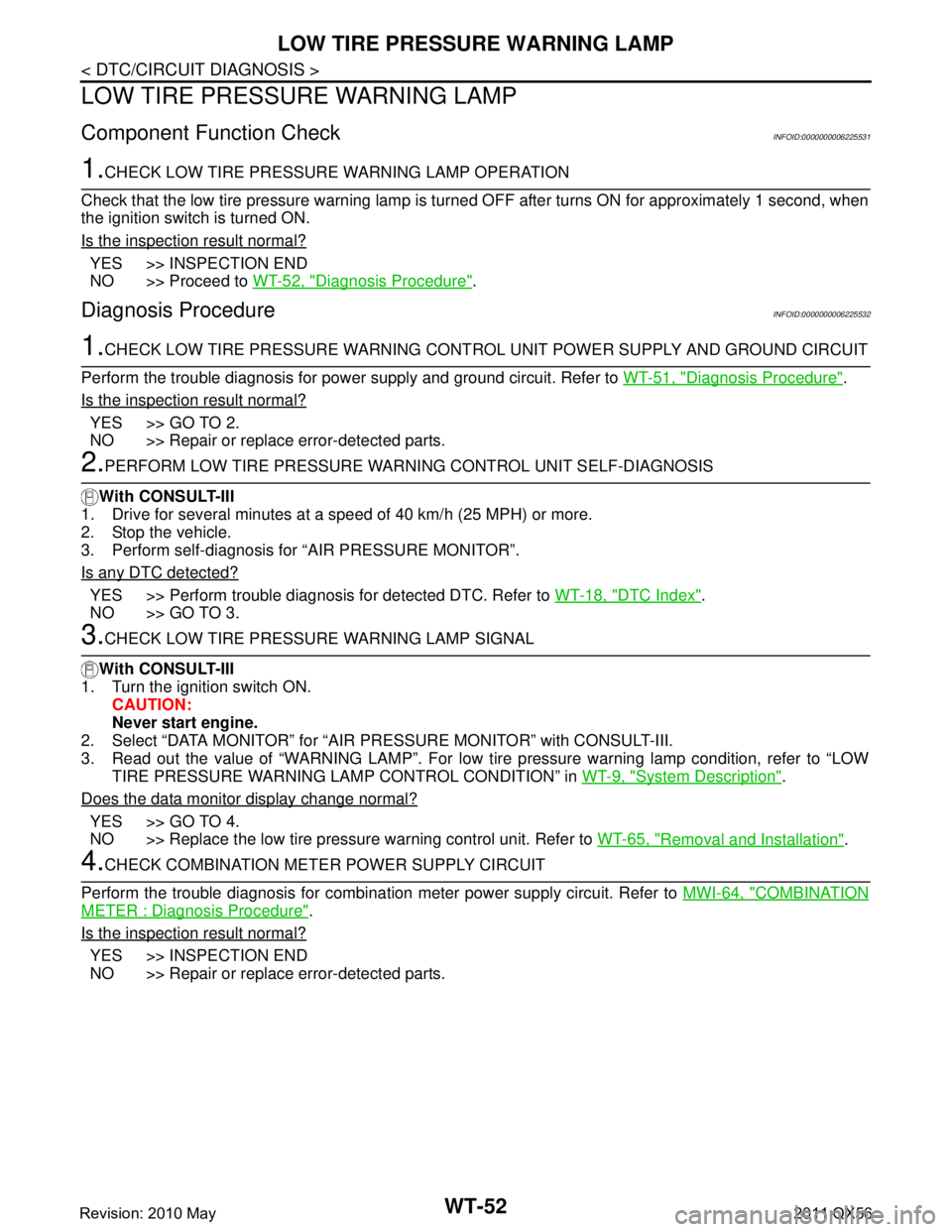
LOW TIRE PRESSURE WARNING LAMP
LOW TIRE PRESSURE WARNING LAMP
Component Function CheckINFOID:0000000006225531
1.CHECK LOW TIRE PRESSURE WARNING LAMP OPERATION
Check that the low tire pressure warning lamp is tu rned OFF after turns ON for approximately 1 second, when
the ignition switch is turned ON.
Is the inspection result normal?
YES >> INSPECTION END
NO >> Proceed to WT-52, "
Diagnosis Procedure".
Diagnosis ProcedureINFOID:0000000006225532
1.CHECK LOW TIRE PRESSURE WARNING CONT ROL UNIT POWER SUPPLY AND GROUND CIRCUIT
Perform the trouble diagnosis for power supply and ground circuit. Refer to WT-51, "
Diagnosis Procedure".
Is the inspection result normal?
YES >> GO TO 2.
NO >> Repair or replace error-detected parts.
2.PERFORM LOW TIRE PRESSURE WARNI NG CONTROL UNIT SELF-DIAGNOSIS
With CONSULT-III
1. Drive for several minutes at a s peed of 40 km/h (25 MPH) or more.
2. Stop the vehicle.
3. Perform self-diagnosis for “AIR PRESSURE MONITOR”.
Is any DTC detected?
YES >> Perform trouble diagnosis for detected DTC. Refer to WT-18, "DTC Index".
NO >> GO TO 3.
3.CHECK LOW TIRE PRESSURE WARNING LAMP SIGNAL
With CONSULT-III
1. Turn the ignition switch ON.
CAUTION:
Never start engine.
2. Select “DATA MONITOR” for “AIR PR ESSURE MONITOR” with CONSULT-III.
3. Read out the value of “WARNING LAMP”. For low tire pressure warning lamp condition, refer to “LOW TIRE PRESSURE WARNING LA MP CONTROL CONDITION” in WT-9, "
System Description".
Does the data monitor display change normal?
YES >> GO TO 4.
NO >> Replace the low tire pressure warning control unit. Refer to WT-65, "
Removal and Installation".
4.CHECK COMBINATION METER POWER SUPPLY CIRCUIT
Perform the trouble diagnosis for combination meter power supply circuit. Refer to MWI-64, "
COMBINATION
METER : Diagnosis Procedure".
Is the inspection result normal?
YES >> INSPECTION END
NO >> Repair or replace error-detected parts.
Revision: 2010 May2011 QX56
Page 5507 of 5598

LOW TIRE PRESSURE WARNING LAMP DOES NOT TURN OFFWT-57
< SYMPTOM DIAGNOSIS >
C
DF
G H
I
J
K L
M A
B
WT
N
O P
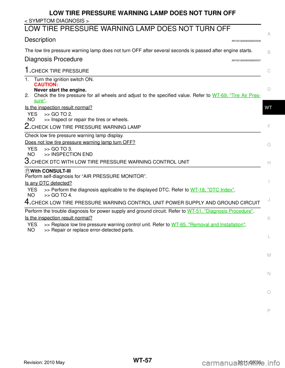
LOW TIRE PRESSURE WARNING LAMP DOES NOT TURN OFF
DescriptionINFOID:0000000006225536
The low tire pressure warning lamp does not turn OFF after several seconds is passed after engine starts.
Diagnosis ProcedureINFOID:0000000006225537
1.CHECK TIRE PRESSURE
1. Turn the ignition switch ON. CAUTION:
Never start the engine.
2. Check the tire pressure for all wheels and adjust to the specified value. Refer to WT-69, "
Tire Air Pres-
sure".
Is the inspection result normal?
YES >> GO TO 2.
NO >> Inspect or repair the tires or wheels.
2.CHECK LOW TIRE PRE SSURE WARNING LAMP
Check low tire pressure warning lamp display.
Does not low tire pressure warning lamp turn OFF?
YES >> GO TO 3.
NO >> INSPECTION END
3.CHECK DTC WITH LOW TIRE PR ESSURE WARNING CONTROL UNIT
With CONSULT-III
Perform self-diagnosis for “AIR PRESSURE MONITOR”.
Is any DTC detected?
YES >> Perform the diagnosis applicable to the displayed DTC. Refer to WT-18, "DTC Index".
NO >> GO TO 4.
4.CHECK LOW TIRE PRESSURE WARNING CONT ROL UNIT POWER SUPPLY AND GROUND CIRCUIT
Perform the trouble diagnosis for power supply and ground circuit. Refer to WT-51, "
Diagnosis Procedure".
Is the inspection result normal?
YES >> Replace low tire pressure warning control unit. Refer to WT-65, "Removal and Installation".
NO >> Repair or replace error-detected parts.
Revision: 2010 May2011 QX56
Page 5509 of 5598

TIRE INFLATION INDICATOR DOES NOT ACTIVATEWT-59
< SYMPTOM DIAGNOSIS >
C
DF
G H
I
J
K L
M A
B
WT
N
O P
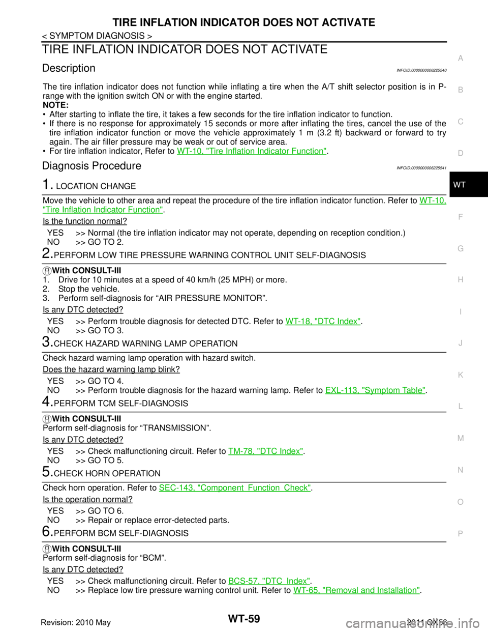
TIRE INFLATION INDICATOR DOES NOT ACTIVATE
DescriptionINFOID:0000000006225540
The tire inflation indicator does not function while inflat ing a tire when the A/T shift selector position is in P-
range with the ignition switch ON or with the engine started.
NOTE:
After starting to inflate the tire, it takes a few seconds for the tire inflation indicator to function.
If there is no response for approximately 15 seconds or mo re after inflating the tires, cancel the use of the
tire inflation indicator function or move the vehicle approximately 1 m (3.2 ft) backward or forward to try
again. The air filler pressure may be weak or out of service area.
For tire inflation indicator, Refer to WT-10, "
Tire Inflation Indicator Function".
Diagnosis ProcedureINFOID:0000000006225541
1. LOCATION CHANGE
Move the vehicle to other area and repeat the procedure of the tire inflation indicator function. Refer to WT-10,
"Tire Inflation Indicator Function".
Is the function normal?
YES >> Normal (the tire inflation indicator may not operate, depending on reception condition.)
NO >> GO TO 2.
2.PERFORM LOW TIRE PRESSURE WARNI NG CONTROL UNIT SELF-DIAGNOSIS
With CONSULT-III
1. Drive for 10 minutes at a speed of 40 km/h (25 MPH) or more.
2. Stop the vehicle.
3. Perform self-diagnosis for “AIR PRESSURE MONITOR”.
Is any DTC detected?
YES >> Perform trouble diagnosis for detected DTC. Refer to WT-18, "DTC Index".
NO >> GO TO 3.
3.CHECK HAZARD WARNING LAMP OPERATION
Check hazard warning lamp operation with hazard switch.
Does the hazard warning lamp blink?
YES >> GO TO 4.
NO >> Perform trouble diagnosis for the hazard warning lamp. Refer to EXL-113, "
Symptom Table".
4.PERFORM TCM SELF-DIAGNOSIS
With CONSULT-III
Perform self-diagnosis for “TRANSMISSION”.
Is any DTC detected?
YES >> Check malfunctioning circuit. Refer to TM-78, "DTC Index".
NO >> GO TO 5.
5.CHECK HORN OPERATION
Check horn operation. Refer to SEC-143, "
ComponentFunctionCheck".
Is the operation normal?
YES >> GO TO 6.
NO >> Repair or replace error-detected parts.
6.PERFORM BCM SELF-DIAGNOSIS
With CONSULT-III
Perform self-diagnosis for “BCM”.
Is any DTC detected?
YES >> Check malfunctioning circuit. Refer to BCS-57, "DTCIndex".
NO >> Replace low tire pressure warning control unit. Refer to WT-65, "
Removal and Installation".
Revision: 2010 May2011 QX56
Page 5537 of 5598

WW-18
< SYSTEM DESCRIPTION >
DIAGNOSIS SYSTEM (IPDM E/R)
DIAGNOSIS SYSTEM (IPDM E/R)
Diagnosis DescriptionINFOID:0000000006349814
AUTO ACTIVE TEST
Description
In auto active test, the IPDM E/R sends a drive signal to the following systems to check their operation.
Oil pressure warning lamp
Rear window defogger
Front wiper (LO, HI)
Parking lamp
License plate lamp
Tail lamp
Side marker lamp
Front fog lamp
Headlamp (LO, HI)
A/C compressor (magnet clutch)
Operation Procedure
CAUTION:
Never perform auto active test in the following conditions.
Engine is running.
CONSULT-III is connected.
1. Close the hood and lift the wiper arms from the windshield. (Prevent windshield damage due to wiper
operation)
NOTE:
When auto active test is performed with hood opened, sprinkle water on windshield beforehand.
2. Turn the ignition switch OFF.
3. Turn the ignition switch ON, and within 20 seconds, pr ess the driver door switch 10 times. Then turn the
ignition switch OFF.
CAUTION:
Close passenger door.
4. Turn the ignition switch ON within 10 seconds. Af ter that the horn sounds once and the auto active test
starts.
CAUTION:
Engine starts when igniti on switch is turned ON while brake pedal is depressed.
5. The oil pressure warning lamp starts blinking when the auto active test starts.
6. After a series of the following operations is repeated 3 times, auto active test is completed.
NOTE:
When auto active test has to be cancelled halfway through test, turn the ignition switch OFF.
When auto active test is not activated, door swit ch may be the cause. Check door switch. Refer to DLK-117,
"ComponentFunctionCheck".
Inspection in Auto Active Test
When auto active test is actuated, the following operation sequence is repeated 3 times.
Operation
sequence Inspection location Operation
1 Oil pressure warning lamp Blinks continuously during operation of auto active test
2 Rear window defogger 10 seconds
3 Front wiper LO for 5 seconds → HI for 5 seconds
4 Parking lamp
License plate lamp
Tail lamp
Side marker lamp
Front fog lamp 10 seconds
Revision: 2010 May2011 QX56