2011 INFINITI QX56 check engine
[x] Cancel search: check enginePage 5418 of 5598

WCS-14
< SYSTEM DESCRIPTION >
DIAGNOSIS SYSTEM (COMBINATION METER)
DIAGNOSIS SYSTEM (COMBINATION METER)
CONSULT-III FunctionINFOID:0000000006222742
CONSULT-III APPLICATION ITEMS
CONSULT-III can perform the following diagnosis modes via CAN communication and the combination meter.
SELF DIAG RESULT
Refer to MWI-43, "DTC Index".
DATA MONITOR
Display Item List
X: Applicable
System Diagnosis mode Description
METER/M&A Self Diagnostic Result The combination meter checks the conditions and displays memorized errors.
Data Monitor Displays the combination meter input/output data in real time.
Special function Lighting history of the warning lamp and indicator lamp can be checked.
Display item [Unit]
MAIN
SIGNALS Description
SPEED METER
[km/h] XValue of vehicle speed
signal received from ABS actuator and el ectric unit (control
unit) via CAN communication.
NOTE:
655.35 is displayed when the malfunction signal is received.
SPEED OUTPUT
[km/h] XVehicle speed signal value transmitted to other units via CAN communication.
NOTE:
655.35 is displayed when the malfunction signal is received.
ODO OUTPUT
[km/h or mph] Odometer signal value transmitted to other units via CAN communication.
TACHO METER
[rpm] XValue of the engine speed signal received from ECM via CAN communication.
NOTE:
8191.875 is displayed when the malfunction signal is received.
FUEL METER
[L] X Fuel level indicated on combination meter.
W TEMP METER
[ ° C] XValue of engine coolant temperature signal is received from ECM via CAN com-
munication.
NOTE:
215 is displayed when the malfunction signal is input.
ABS W/L
[On/Off] Status of ABS warning lamp
detected from ABS warning lamp signal is received
from ABS actuator and electric unit (control unit) via CAN communication.
VDC/TCS IND
[On/Off] Status of VDC OFF indicator lamp detected from VDC OFF indicator lamp signal
is received from ABS actuator and electric
unit (control unit) via CAN communica-
tion.
SLIP IND
[On/Off] Status of VDC warning lamp detected from VDC warning lamp signal received
from ABS actuator and electric unit (control unit) via CAN communication.
BRAKE W/L
[On/Off] Status of brake warning lamp detected from brake warning lamp signal is received
from ABS actuator and electric unit (control unit) via CAN communication.
NOTE:
Displays “Off” if the brake warning lamp is illuminated when the valve check starts,
the parking brake switch is turned ON or the brake fluid level switch is turned ON.
DOOR W/L
[On/Off] Status of door open warning detected from door switch signal received from BCM
via CAN communication.
HI-BEAM IND
[On/Off] Status of high beam indicator lamp detected from high beam request signal is re-
ceived from BCM via CAN communication.
TURN IND
[On/Off] Status of turn indicator lamp detected from turn indicator signal is received from
BCM via CAN communication.
Revision: 2010 May2011 QX56
Page 5421 of 5598

WCS
DIAGNOSIS SYSTEM (COMBINATION METER)
WCS-17
< SYSTEM DESCRIPTION >
C
D E
F
G H
I
J
K L
M B A
O P
*: DDS (hill descent control) NOTE:
Some items are not available according to vehicle specification.
SPECIAL FUNCTION
Special menu
W/L ON HISTORY
Stores histories when warning/indicator lamp is turned on.
“W/L ON HISTORY” indicates the “TIME” when the warning/ indicator lamp is turned on.
The “TIME” above is:
- 0: The condition that the warning/indicator lamp has been turned on 1 or more times after starting the engine and waiting for 30 seconds.
- 1 - 39: The number of times the engine was restarted after the 0 condition.
- NO W/L ON HISTORY: Stores NO (0) turning on history of warning/indicator lamp.
NOTE:
W/L ON HISTORY is not stored for approximately 30 seconds after the engine starts.
Brake warning lamp does not store any history when the parking brake is applied or the brake fluid level gets
low.
Display Item
FUEL LOW SIG
[On/Off] Status of fuel level low warning signal to output to AV control unit via CAN com-
munication.
TOW MODE IND
[On/Off] Status of TOW mode indicator lamp judged from TOW mode indicator lamp signal
received from TCM with CAN communication line.
BUZZER
[On/Off] XBuzzer status (in the combination meter) is detected from the buzzer output signal
received from each unit via CAN communication and the warning output condition
of the combination meter.
Display item [Unit]
MAIN
SIGNALS Description
Display item Description
W/L ON HISTORY Lighting history of warning lamp and indicator lamp can be checked.
Display item Description
ABS W/L Lighting history of ABS warning lamp.
VDC/TCS IND Lighting history of VDC OFF indicator lamp.
SLIP IND Lighting history of VDC warning lamp.
BRAKE W/L Lighting history of brake warning lamp.
DOOR W/L Lighting history of door open warning.
TRUNK/GLAS-H This item is displayed, but cannot be monitored.
OIL W/L Lighting history of oil pressure warning lamp.
C-ENG W/L Lighting history of malfunction indicator lamp.
C-ENG2 W/L This item is displayed, but cannot be monitored.
CRUISE IND Lighting history of CRUISE indicator lamp.
SET IND Lighting history of SET indicator lamp.
CRUISE W/L Lighting histor y of CRUISE warning lamp.
BA W/L Lighting history of IBA OFF indicator lamp.
O/D OFF IND This item is displayed, but cannot be monitored.
ATC/T-AMT W/L Lighting history of A/T CHECK warning lamp.
ATF TEMP W/L This item is displayed, but cannot be monitored.
CVT IND This item is displayed, but cannot be monitored.
SPORT IND This item is displayed, but cannot be monitored.
Revision: 2010 May2011 QX56
Page 5424 of 5598

WCS-20
< SYSTEM DESCRIPTION >
DIAGNOSIS SYSTEM (BCM)
BUZZER
BUZZER : CONSULT-III Function (BCM - BUZZER)INFOID:0000000006222687
CONSULT-III APPLICATION ITEMS
DATA MONITOR
CONSULT screen item Indication/Unit Description
Vehicle Speed km/h Vehicle speed of the moment a particular DTC is detected
Odo/Trip Meter km Total mileage (Odometer value) of the moment a particular DTC is detected
Vehicle Condition SLEEP>LOCK
Power position status of
the moment a particular
DTC is detected While turning BCM status from low power consumption mode to
normal mode (Power supply position is “LOCK”)
SLEEP>OFF While turning BCM status from low power consumption mode to
normal mode (Power supply position is “OFF”.)
LOCK>ACC While turning power supply position from “LOCK” to “ACC”
ACC>ON While turning power supply position from “ACC” to “IGN”
RUN>ACC While turning power supp
ly position from “RUN” to “ACC” (Vehicle
is stopping and selector lever is except P position.)
CRANK>RUN While turning power su
pply position from “CRANKING” to “RUN”
(From cranking up the engine to run it)
RUN>URGENT While turning power supply positi
on from “RUN“ to “ACC” (Emer-
gency stop operation)
ACC>OFF While turning power supply position from “ACC” to “OFF”
OFF>LOCK While turning power supply position from “OFF” to “LOCK”
OFF>ACC While turning power supply position from “OFF” to “ACC”
ON>CRANK While turning power supply position from “IGN” to “CRANKING”
OFF>SLEEP While turning BCM status from normal mode (Power supply posi-
tion is “OFF”.) to low power consumption mode
LOCK>SLEEP While turning BCM status from normal mode (Power supply posi-
tion is “LOCK”.) to low power consumption mode
LOCK Power supply position is “LOCK”
(Ignition switch OFF with steer-
ing is locked.)
OFF Power supply position is “OFF” (Ignition switch OFF with steering
is unlocked.)
ACC Power supply position is “ACC” (Ignition switch ACC)
ON Power supply position is “IGN” (Ignition switch ON with engine
stopped)
ENGINE RUN Power supply position is “RUN” (Ignition switch ON with engine
running)
CRANKING Power supply position is “CRANKING” (At engine cranking)
IGN Counter 0 - 39 The number of times that ignition switch is turned ON after DTC is detected
The number is 0 when a malfunction is detected now.
The number increases like 1
→ 2 → 3...38 → 39 after returning to the normal condition
whenever ignition switch OFF → ON.
The number is fixed to 39 until the self-diagnosis results are erased if it is over 39.
Test item Diagnosis mode Description
BUZZER Data Monitor Displays BCM input data in real time.
Active Test Operation of electrical loads can be checked by sending driving signal to them.
Revision: 2010 May2011 QX56
Page 5428 of 5598

WCS-24
< ECU DIAGNOSIS INFORMATION >
COMBINATION METER
DCA INDIgnition switch
ONNOTE:
This item is displayed, but cannot be moni-
tored.
Off
CHECK SUS IND Ignition switch
ONCK SUSP indicator lamp ON On
CK SUSP indicator lamp OFF Off
LCD Ignition switch
ON
During engine start in
formation indication B&P I
Ignition switch
ACC During engine start information indication B&P N
Ignition switch
LOCK During key ID warning indication ID NG
Ignition switch
LOCK During steering lock information indication ROTAT
Ignition switch
LOCK During P position warning indication SFT P
Ignition switch
LOCK During Intelligent Key insert information in-
dication
INSRT
Ignition switch
LOCK During Intelligent Key low battery warning
indication
BATT
Ignition switch
ON During take away warning indication NO KY
Ignition switch
LOCK During key warnin
g indication OUTKY
Ignition switch
ON During ACC warning indication LK WN
ACC TARGET Ignition switch
ONDuring vehicle ahead detection indicator in-
dication
On
Other than the above Off
ACC DISTANCE Ignition switch
ONWhen following distance set to “LONG” LONG
When following distance set to “MIDDLE” MID
When following distance set to “SHORT” SHORT
Set distance indicator not displayed Off
ACC OWN VHL Ignition switch
ONDuring own vehicle indicator indication On
Other than the above Off
ACC SET SPEED Ignition switch
ONDuring set vehicle speed indicator not dis-
played
Off
During set vehicle speed indicator dis-
played Indicates the set vehicle speed
ACC UNIT Ignition switch
ONSet vehicle speed indicator unit display ON On
Set vehicle speed indicator unit display OFF Off
Monitor Item Condition Value/Status
Revision: 2010 May2011 QX56
Page 5434 of 5598

WCS-30
< ECU DIAGNOSIS INFORMATION >
COMBINATION METER
DTC Index
INFOID:0000000006222690
Warning lamp/indicator lamp ABS warning lamp
The lamp turns ON by suspending communication.
VDC warning lamp
Brake warning lamp
IBA OFF indicator lamp
4WD warning lamp
Malfunction indicator lamp
VDC OFF indicator lamp
CRUISE warning lamp
Low tire pressure warning lamp The lamp blinking caused by suspending communication.
High beam indicator lamp
The lamp turns OFF by suspending communication.
Turn signal indicator lamp
Tail lamp indicator lamp
A/T CHECK indicator lamp
Key warning lamp
ATP warning lamp
Lane departure warning lamp
LDP ON indicator lamp
CRUISE indicator lamp
Oil pressure warning lamp
SNOW mode indicator lamp
TOW mode indicator lamp
CK SUSP indicator lamp
BSW indicator lamp
Function Specifications
Display contents of CONSULT-III Diagnostic item is detected when... Refer to
CAN COMM CIRCUIT
[U1000] When combination meter is not transmitting or receiving CAN communication signal
for 2 seconds or more. MWI-59,
"Diagnosis
Procedure"
CONTROL UNIT (CAN)
[U1010]
When detecting error during the initial diagnosis of the CAN controller of combina-
tion meter. MWI-60, "Diagnosis
Procedure"
VEHICLE SPEED
[B2205]
The abnormal vehicle sp
eed signal is input from the ABS actuator and electric unit
(control unit) for 2 seconds or more. MWI-61, "Diagnosis
Procedure"
ENGINE SPEED
[B2267]
If ECM continuously transmits abnormal engine speed signals for 2 seconds or
more. MWI-62, "Diagnosis
Procedure"
WATER TEMP
[B2268]
If ECM continuously transmits abnormal engine coolant temperature signals for 60
seconds or more. MWI-63, "Diagnosis
Procedure"
Revision: 2010 May2011 QX56
Page 5450 of 5598

WCS-46
< SYMPTOM DIAGNOSIS >
THE PARKING BRAKE RELEASE WARNING CONTINUES SOUNDING, OR
DOES NOT SOUND
THE PARKING BRAKE RELEASE WARNING CONTINUES SOUNDING, OR
DOES NOT SOUND
DescriptionINFOID:0000000006222534
The parking brake warning buzzer sounds continuously during vehicle travel though the parking brake is
released.
The parking brake warning buzzer does not sound at a ll even though driving the vehicle with the parking
brake applied.
Diagnosis ProcedureINFOID:0000000006222535
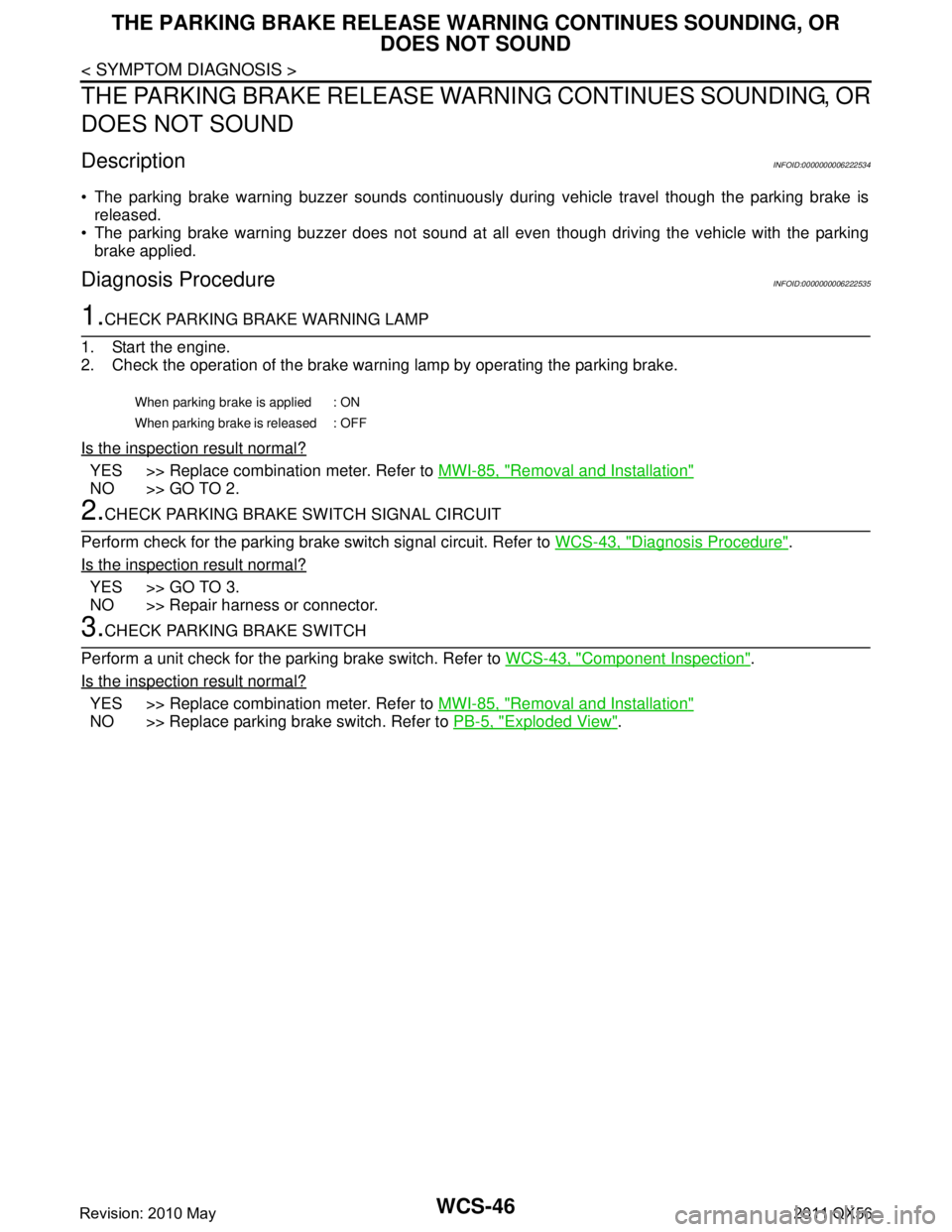
1.CHECK PARKING BRAKE WARNING LAMP
1. Start the engine.
2. Check the operation of the brake warni ng lamp by operating the parking brake.
Is the inspection result normal?
YES >> Replace combination meter. Refer to MWI-85, "Removal and Installation"
NO >> GO TO 2.
2.CHECK PARKING BRAKE SWITCH SIGNAL CIRCUIT
Perform check for the parking brake switch signal circuit. Refer to WCS-43, "
Diagnosis Procedure".
Is the inspection result normal?
YES >> GO TO 3.
NO >> Repair harness or connector.
3.CHECK PARKING BRAKE SWITCH
Perform a unit check for the parking brake switch. Refer to WCS-43, "
Component Inspection".
Is the inspection result normal?
YES >> Replace combination meter. Refer to MWI-85, "Removal and Installation"
NO >> Replace parking brake switch. Refer to PB-5, "Exploded View".
When parking brake is applied : ON
When parking brake is released : OFF
Revision: 2010 May2011 QX56
Page 5464 of 5598

WT-14
< ECU DIAGNOSIS INFORMATION >
LOW TIRE PRESSURE WARNING CONTROL UNIT
ECU DIAGNOSIS INFORMATION
LOW TIRE PRESSURE WARNING CONTROL UNIT
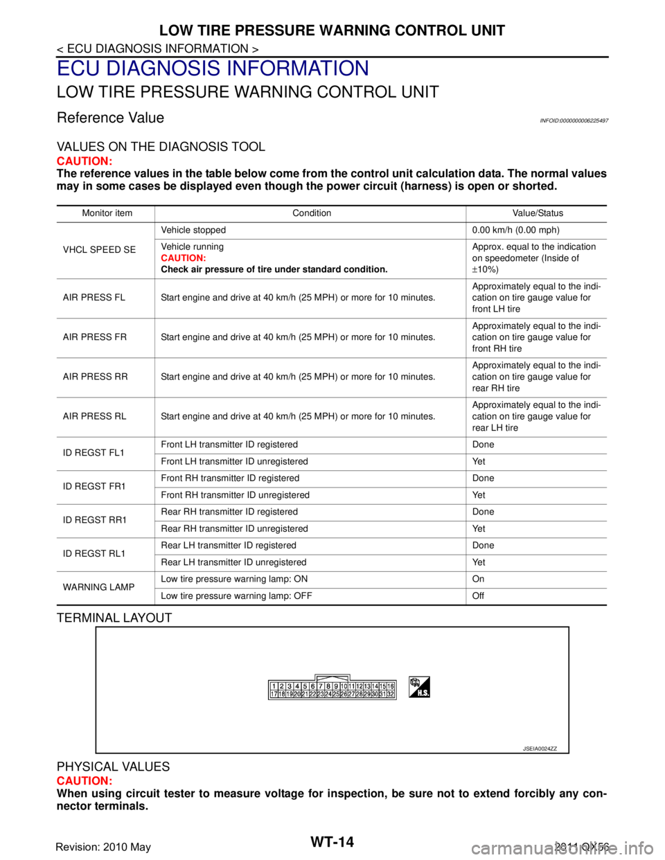
Reference ValueINFOID:0000000006225497
VALUES ON THE DIAGNOSIS TOOL
CAUTION:
The reference values in the table below come from the control unit calculation data. The normal values
may in some cases be displayed even though the power circuit (harness) is open or shorted.
TERMINAL LAYOUT
PHYSICAL VALUES
CAUTION:
When using circuit tester to measure voltage for in spection, be sure not to extend forcibly any con-
nector terminals.
Monitor item Condition Value/Status
VHCL SPEED SE Vehicle stopped 0.00 km/h (0.00 mph)
Vehicle running
CAUTION:
Check air pressure of tire under standard condition. Approx. equal to the indication
on speedometer (Inside of
±
10%)
AIR PRESS FL Start engine and drive at 40 km/h (25 MPH) or more for 10 minutes. Approximately equal to the indi-
cation on tire gauge value for
front LH tire
AIR PRESS FR Start engine and drive at 40 km/h (25 MPH) or more for 10 minutes. Approximately equal to the indi-
cation on tire gauge value for
front RH tire
AIR PRESS RR Start engine and drive at 40 km/h (25 MPH) or more for 10 minutes. Approximately equal to the indi-
cation on tire gauge value for
rear RH tire
AIR PRESS RL Start engine and drive at 40 km/h (25 MPH) or more for 10 minutes. Approximately equal to the indi-
cation on tire gauge value for
rear LH tire
ID REGST FL1 Front LH transmitter ID registered Done
Front LH transmitter ID unregistered Yet
ID REGST FR1 Front RH transmitter ID registered Done
Front RH transmitter ID unregistered Yet
ID REGST RR1 Rear RH transmitter ID registered Done
Rear RH transmitter ID unregistered Yet
ID REGST RL1 Rear LH transmitter ID registered Done
Rear LH transmitter ID unregistered Yet
WARNING LAMP Low tire pressure
warning lamp: ON On
Low tire pressure warning lamp: OFF Off
JSEIA0024ZZ
Revision: 2010 May2011 QX56
Page 5475 of 5598

DIAGNOSIS AND REPAIR WORK FLOWWT-25
< BASIC INSPECTION >
C
DF
G H
I
J
K L
M A
B
WT
N
O P
BASIC INSPECTION
DIAGNOSIS AND REPAIR WORK FLOW
Work Flow INFOID:0000000006225501
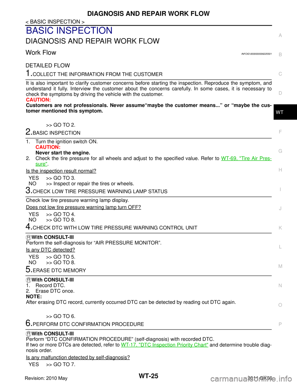
DETAILED FLOW
1.COLLECT THE INFORMATION FROM THE CUSTOMER
It is also important to clarify customer concerns before starting the inspection. Reproduce the symptom, and
understand it fully. Interview the customer about the concer ns carefully. In some cases, it is necessary to
check the symptoms by driving the vehicle with the customer.
CAUTION:
Customers are not professionals. Never assume“mayb e the customer means...” or “maybe the cus-
tomer mentioned this symptom.
>> GO TO 2.
2.BASIC INSPECTION
1. Turn the ignition switch ON. CAUTION:
Never start the engine.
2. Check the tire pressure for all wheels and adjust to the specified value. Refer to WT-69, "
Tire Air Pres-
sure".
Is the inspection result normal?
YES >> GO TO 3.
NO >> Inspect or repair the tires or wheels.
3.CHECK LOW TIRE PRESSURE WARNING LAMP STATUS
Check low tire pressure warning lamp display.
Does not low tire pressure warning lamp turn OFF?
YES >> GO TO 4.
NO >> GO TO 8.
4.CHECK DTC WITH LOW TIRE PR ESSURE WARNING CONTROL UNIT
With CONSULT-III
Perform the self-diagnosis fo r “AIR PRESSURE MONITOR”.
Is any DTC detected?
YES >> GO TO 5.
NO >> GO TO 8.
5.ERASE DTC MEMORY
With CONSULT-III
1. Record DTC.
2. Erase DTC once.
NOTE:
After erasing DTC record, currently occurr ed DTC can be detected by reading out DTC again.
>> GO TO 6.
6.PERFORM DTC CONFIRMATION PROCEDURE
With CONSULT-III
Perform “DTC CONFIRMATION PROCEDURE” (self-diagnosis) with recorded DTC.
If two or more DTCs are detected, refer to WT-17, "
DTC Inspection Priority Chart" and determine trouble diag-
nosis order.
Is any malfunction detected by self-diagnosis?
YES >> GO TO 7.
Revision: 2010 May2011 QX56