2011 INFINITI QX56 check engine
[x] Cancel search: check enginePage 5476 of 5598
WT-26
< BASIC INSPECTION >
DIAGNOSIS AND REPAIR WORK FLOW
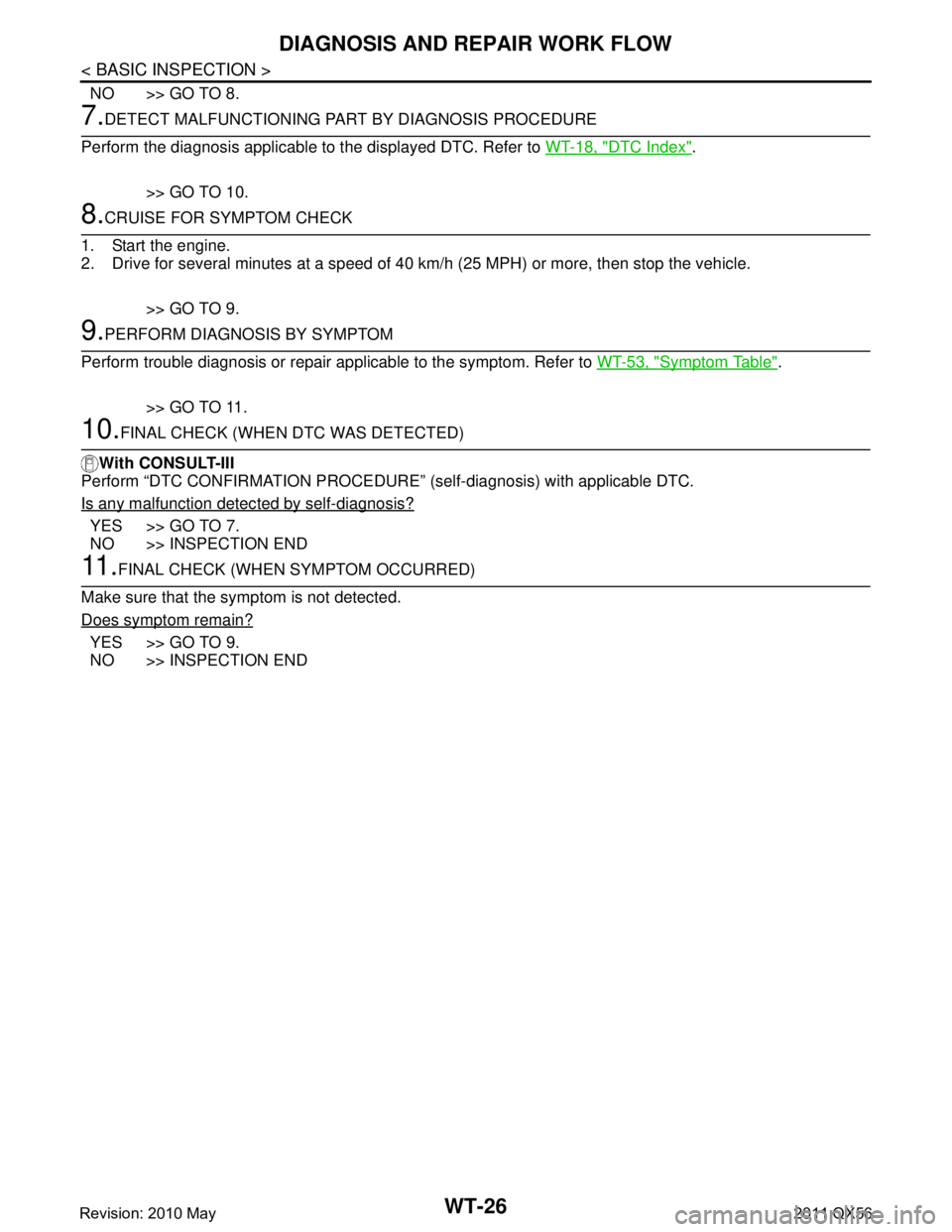
NO >> GO TO 8.
7.DETECT MALFUNCTIONING PART BY DIAGNOSIS PROCEDURE
Perform the diagnosis applicable to the displayed DTC. Refer to WT-18, "
DTC Index".
>> GO TO 10.
8.CRUISE FOR SYMPTOM CHECK
1. Start the engine.
2. Drive for several minutes at a speed of 40 km /h (25 MPH) or more, then stop the vehicle.
>> GO TO 9.
9.PERFORM DIAGNOSIS BY SYMPTOM
Perform trouble diagnosis or repair applicable to the symptom. Refer to WT-53, "
Symptom Table".
>> GO TO 11.
10.FINAL CHECK (WHEN DTC WAS DETECTED)
With CONSULT-III
Perform “DTC CONFIRMATION PROCE DURE” (self-diagnosis) with applicable DTC.
Is any malfunction detec ted by self-diagnosis?
YES >> GO TO 7.
NO >> INSPECTION END
11 .FINAL CHECK (WHEN SYMPTOM OCCURRED)
Make sure that the symptom is not detected.
Does symptom remain?
YES >> GO TO 9.
NO >> INSPECTION END
Revision: 2010 May2011 QX56
Page 5481 of 5598
C1704, C1705, C1706, C1707 LOW TIRE PRESSURE
WT-31
< DTC/CIRCUIT DIAGNOSIS >
C
D F
G H
I
J
K L
M A
B
WT
N
O P
DTC/CIRCUIT DIAGNOSIS
C1704, C1705, C1706, C1707 LOW TIRE PRESSURE
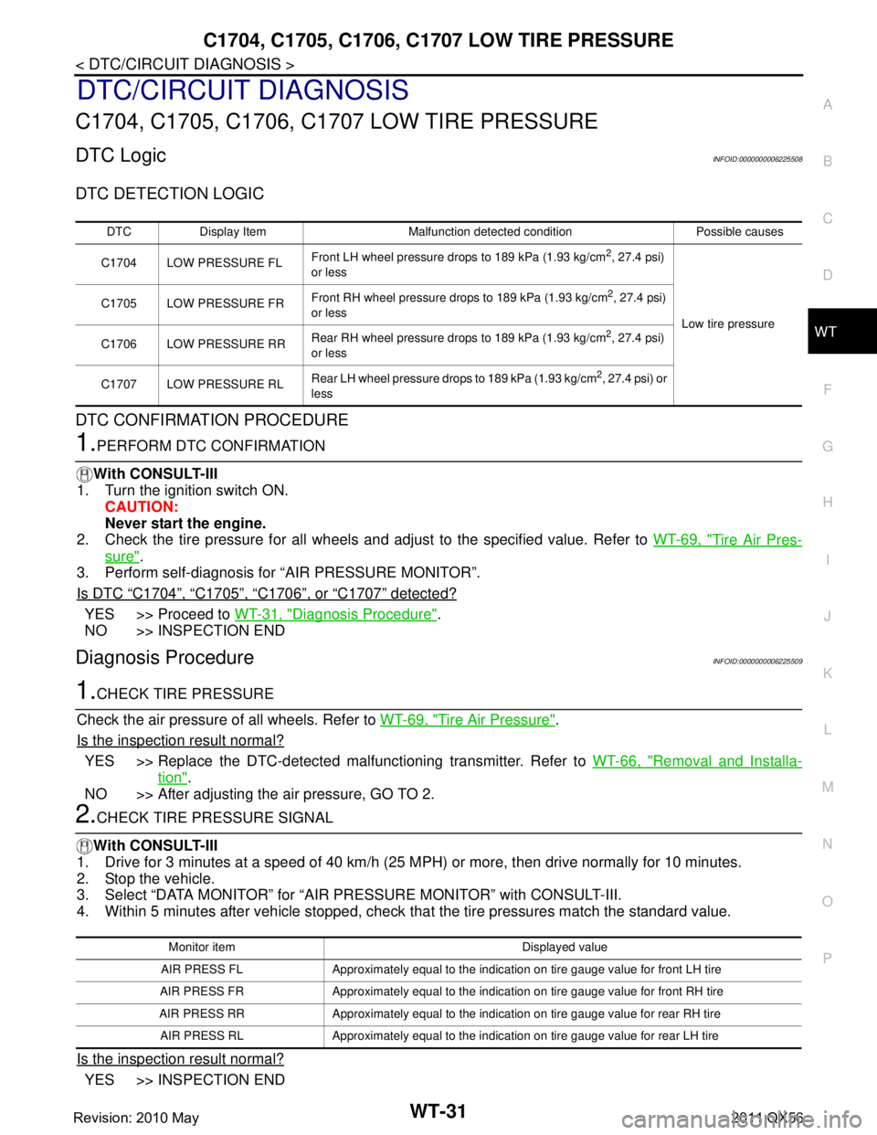
DTC LogicINFOID:0000000006225508
DTC DETECTION LOGIC
DTC CONFIRMATION PROCEDURE
1.PERFORM DTC CONFIRMATION
With CONSULT-III
1. Turn the ignition switch ON.
CAUTION:
Never start the engine.
2. Check the tire pressure for all wheels and adjust to the specified value. Refer to WT-69, "
Tire Air Pres-
sure".
3. Perform self-diagnosis for “AIR PRESSURE MONITOR”.
Is DTC
“C1704”, “C1705”, “C1706”, or “C1707” detected?
YES >> Proceed to WT-31, "Diagnosis Procedure".
NO >> INSPECTION END
Diagnosis ProcedureINFOID:0000000006225509
1.CHECK TIRE PRESSURE
Check the air pressure of all wheels. Refer to WT-69, "
Tire Air Pressure".
Is the inspection result normal?
YES >> Replace the DTC-detected malfunctioning transmitter. Refer to WT-66, "Removal and Installa-
tion".
NO >> After adjusting the air pressure, GO TO 2.
2.CHECK TIRE PRESSURE SIGNAL
With CONSULT-III
1. Drive for 3 minutes at a speed of 40 km/h (25 MPH) or more, then drive normally for 10 minutes.
2. Stop the vehicle.
3. Select “DATA MONITOR” for “AIR PRESSURE MONITOR” with CONSULT-III.
4. Within 5 minutes after vehicle stopped, check t hat the tire pressures match the standard value.
Is the inspection result normal?
YES >> INSPECTION END
DTC Display Item Malfunction detected condition Possible causes
C1704 LOW PRESSURE FL Front LH wheel pressure drops to 189 kPa (1.93 kg/cm
2, 27.4 psi)
or less
Low tire pressure
C1705 LOW PRESSURE FR
Front RH wheel pressure drops to 189 kPa (1.93 kg/cm
2, 27.4 psi)
or less
C1706 LOW PRESSURE RR Rear RH wheel pressure drops to 189 kPa (1.93 kg/cm
2, 27.4 psi)
or less
C1707 LOW PRESSURE RL Rear LH wheel pressure drops to 189 kPa (1.93 kg/cm
2, 27.4 psi) or
less
Monitor item Displayed value
AIR PRESS FL Approximately equal to the indication on tire gauge value for front LH tire
AIR PRESS FR Approximately equal to the indication on tire gauge value for front RH tire
AIR PRESS RR Approximately equal to the indica tion on tire gauge value for rear RH tire
AIR PRESS RL Approximately equal to the indication on tire gauge value for rear LH tire
Revision: 2010 May2011 QX56
Page 5485 of 5598
C1708, C1709, C1710, C1711 TRANSMITTER (NO DATA)
WT-35
< DTC/CIRCUIT DIAGNOSIS >
C
DF
G H
I
J
K L
M A
B
WT
N
O P
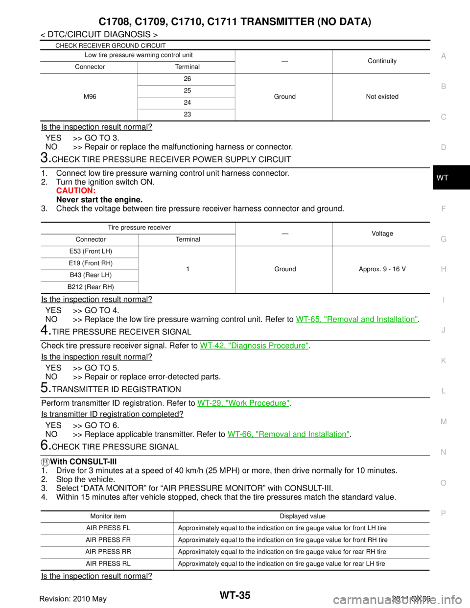
CHECK RECEIVER GROUND CIRCUIT
Is the inspection result normal?
YES >> GO TO 3.
NO >> Repair or replace the malfunctioning harness or connector.
3.CHECK TIRE PRESSURE RECE IVER POWER SUPPLY CIRCUIT
1. Connect low tire pressure warning control unit harness connector.
2. Turn the ignition switch ON. CAUTION:
Never start the engine.
3. Check the voltage between tire pressure receiver harness connector and ground.
Is the inspection result normal?
YES >> GO TO 4.
NO >> Replace the low tire pressure warning control unit. Refer to WT-65, "
Removal and Installation".
4.TIRE PRESSURE RECEIVER SIGNAL
Check tire pressure receiver signal. Refer to WT-42, "
Diagnosis Procedure".
Is the inspection result normal?
YES >> GO TO 5.
NO >> Repair or replace error-detected parts.
5.TRANSMITTER ID REGISTRATION
Perform transmitter ID registration. Refer to WT-29, "
Work Procedure".
Is transmitter ID registration completed?
YES >> GO TO 6.
NO >> Replace applicable transmitter. Refer to WT-66, "
Removal and Installation".
6.CHECK TIRE PRESSURE SIGNAL
With CONSULT-III
1. Drive for 3 minutes at a speed of 40 km/h (25 MPH) or more, then drive normally for 10 minutes.
2. Stop the vehicle.
3. Select “DATA MONITOR” for “AIR PRESSURE MONITOR” with CONSULT-III.
4. Within 15 minutes after vehicle stopped, check t hat the tire pressures match the standard value.
Is the inspection result normal?
Low tire pressure warning control unit
—Continuity
Connector Terminal
M96 26
Ground Not existed
25
24
23
Tire pressu
re receiver
—Voltage
Connector Terminal
E53 (Front LH)
1 Ground Approx. 9 - 16 V
E19 (Front RH)
B43 (Rear LH)
B212 (Rear RH)
Monitor item Displayed value
AIR PRESS FL Approximately equal to the indication on tire gauge value for front LH tire
AIR PRESS FR Approximately equal to the indication on tire gauge value for front RH tire
AIR PRESS RR Approximately equal to the indica tion on tire gauge value for rear RH tire
AIR PRESS RL Approximately equal to the indication on tire gauge value for rear LH tire
Revision: 2010 May2011 QX56
Page 5487 of 5598
C1716, C1717, C1718, C1719 TRANSMITTER (PRESSURE DATA)
WT-37
< DTC/CIRCUIT DIAGNOSIS >
C
DF
G H
I
J
K L
M A
B
WT
N
O P
C1716, C1717, C1718, C1719 TRAN SMITTER (PRESSURE DATA)
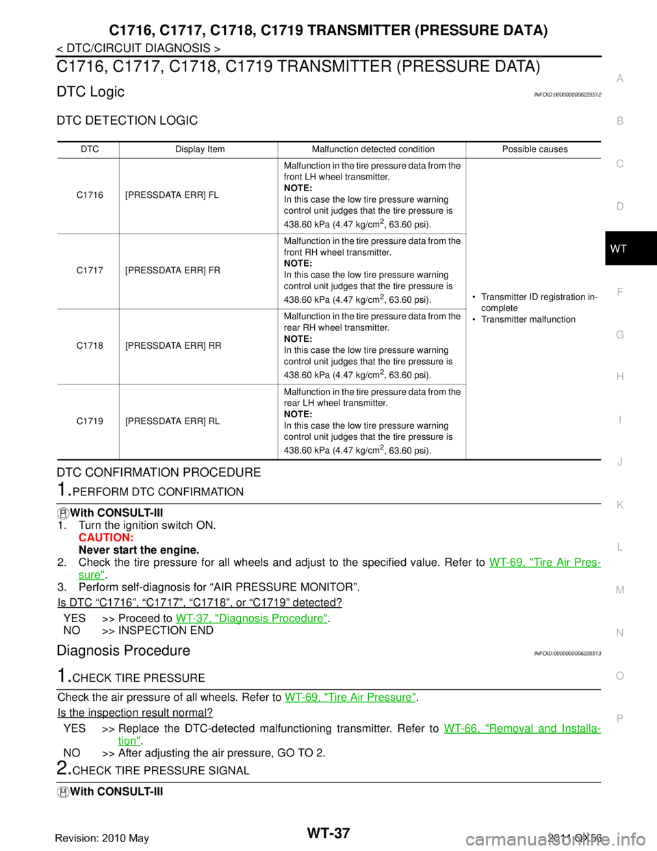
DTC LogicINFOID:0000000006225512
DTC DETECTION LOGIC
DTC CONFIRMATION PROCEDURE
1.PERFORM DTC CONFIRMATION
With CONSULT-III
1. Turn the ignition switch ON.
CAUTION:
Never start the engine.
2. Check the tire pressure for all wheels and adjust to the specified value. Refer to WT-69, "
Tire Air Pres-
sure".
3. Perform self-diagnosis for “AIR PRESSURE MONITOR”.
Is DTC
“C1716”, “C1717”, “C1718”, or “C1719” detected?
YES >> Proceed to WT-37, "Diagnosis Procedure".
NO >> INSPECTION END
Diagnosis ProcedureINFOID:0000000006225513
1.CHECK TIRE PRESSURE
Check the air pressure of all wheels. Refer to WT-69, "
Tire Air Pressure".
Is the inspection result normal?
YES >> Replace the DTC-detected malfunctioning transmitter. Refer to WT-66, "Removal and Installa-
tion".
NO >> After adjusting the air pressure, GO TO 2.
2.CHECK TIRE PRESSURE SIGNAL
With CONSULT-III
DTC Display Item Malfunction detected condition Possible causes
C1716 [PRESSDATA ERR] FL Malfunction in the tire pressure data from the
front LH wheel transmitter.
NOTE:
In this case the low tire pressure warning
control unit judges that the tire pressure is
438.60 kPa (4.47 kg/cm
2, 63.60 psi).
Transmitter ID registration in-
complete
Transmitter malfunction
C1717 [PRESSDATA ERR] FR
Malfunction in the tire pressure data from the
front RH wheel transmitter.
NOTE:
In this case the low tire pressure warning
control unit judges that the tire pressure is
438.60 kPa (4.47 kg/cm
2, 63.60 psi).
C1718 [PRESSDATA ERR] RR Malfunction in the tire pressure data from the
rear RH wheel transmitter.
NOTE:
In this case the low tire pressure warning
control unit judges that the tire pressure is
438.60 kPa (4.47 kg/cm
2, 63.60 psi).
C1719 [PRESSDATA ERR] RL Malfunction in the tire pressure data from the
rear LH wheel transmitter.
NOTE:
In this case the low tire pressure warning
control unit judges that the tire pressure is
438.60 kPa (4.47 kg/cm
2, 63.60 psi).
Revision: 2010 May2011 QX56
Page 5489 of 5598
C1728 RECEIVER IDWT-39
< DTC/CIRCUIT DIAGNOSIS >
C
DF
G H
I
J
K L
M A
B
WT
N
O P
C1728 RECEIVER ID
DTC LogicINFOID:0000000006225514
DTC DETECTION LOGIC
DTC CONFIRMATION PROCEDURE
1.PERFORM DTC CONFIRMATION
With CONSULT-III
1. Drive for 3 minutes at a speed of 40 km/h (25 MPH) or more, then drive normally for 10 minutes.
2. Stop the vehicle.
3. Perform self-diagnosis for “AIR PRESSURE MONITOR”.
Is DTC
“C1728” detected?
YES >> Proceed to WT-39, "Diagnosis Procedure".
NO >> INSPECTION END
Diagnosis ProcedureINFOID:0000000006225515
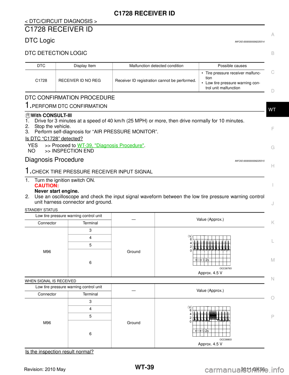
1.CHECK TIRE PRESSURE RECEIVER INPUT SIGNAL
1. Turn the ignition switch ON. CAUTION:
Never start engine.
2. Use an oscilloscope and check the input signal waveform between the low tire pressure warning control
unit harness connector and ground.
STANDBY STATUS
WHEN SIGNAL IS RECEIVED
Is the inspection result normal?
DTC Display Item Malfunction detected condition Possible causes
C1728 RECEIVER ID NO REG Receiver ID registration cannot be performed. Tire pressure receiver malfunc-
tion
Low tire pressure warning con- trol unit malfunction
Low tire pressure warning control unit — Value (Approx.)
Connector Terminal
M96 3
Ground
Approx. 4.5 V
4
5
6
Low tire pressure warning control unit — Value (Approx.)
Connector Terminal
M96 3
Ground Approx. 4.5 V
4
5
6
OCC3879D
OCC3880D
Revision: 2010 May2011 QX56
Page 5490 of 5598
WT-40
< DTC/CIRCUIT DIAGNOSIS >
C1728 RECEIVER ID
YES >> Check connector for loose connection and then perform “DTC CONFIRMATION PROCEDURE”
(self-diagnosis) again. Refer to WT-39, "
DTC Logic".
NO >> GO TO 2.
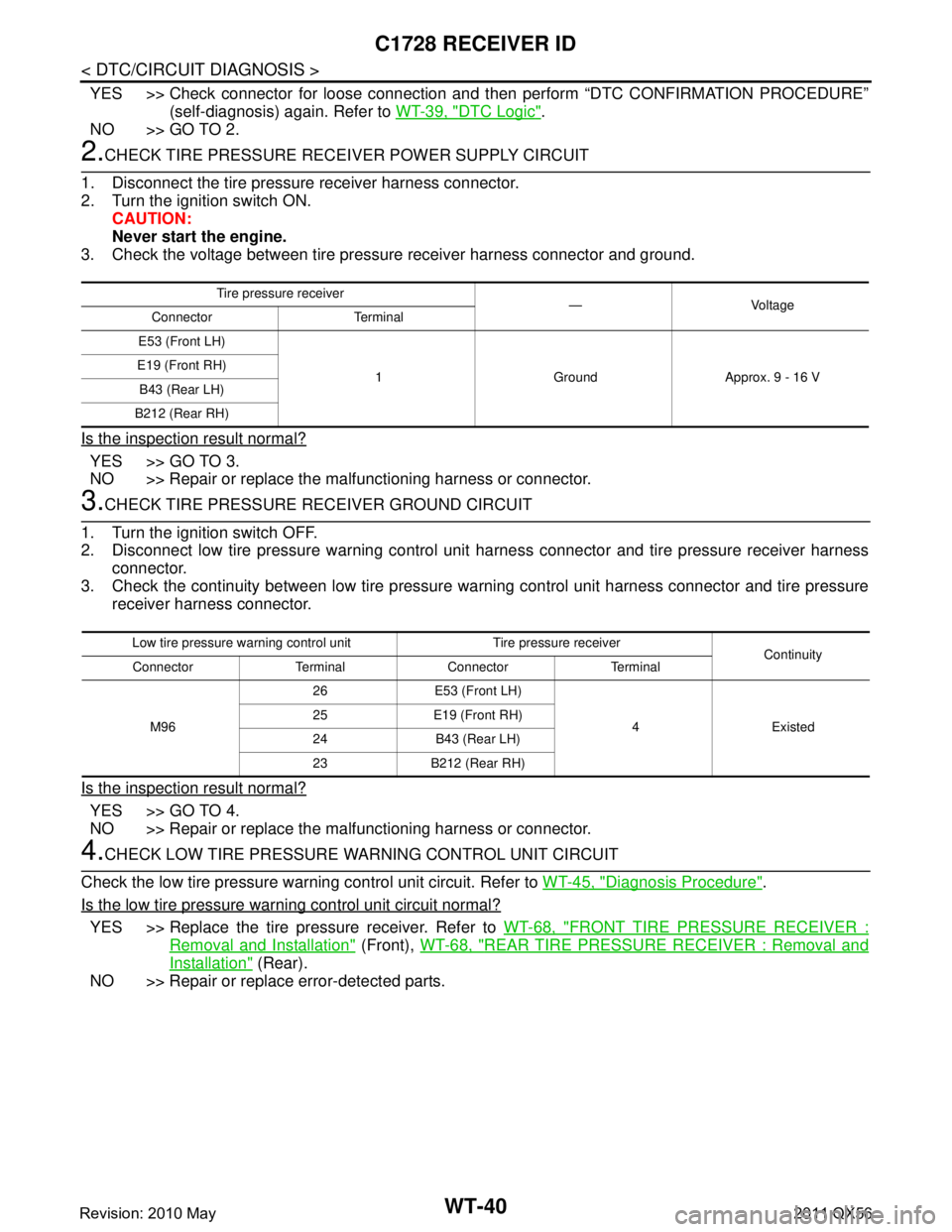
2.CHECK TIRE PRESSURE RECEI VER POWER SUPPLY CIRCUIT
1. Disconnect the tire pressure receiver harness connector.
2. Turn the ignition switch ON. CAUTION:
Never start the engine.
3. Check the voltage between tire pressure receiver harness connector and ground.
Is the inspection result normal?
YES >> GO TO 3.
NO >> Repair or replace the ma lfunctioning harness or connector.
3.CHECK TIRE PRESSURE RECEIVER GROUND CIRCUIT
1. Turn the ignition switch OFF.
2. Disconnect low tire pressure warning control unit harness connector and tire pressure receiver harness
connector.
3. Check the continuity between low tire pressure warning control unit harness connector and tire pressure receiver harness connector.
Is the inspection result normal?
YES >> GO TO 4.
NO >> Repair or replace the ma lfunctioning harness or connector.
4.CHECK LOW TIRE PRESSURE WARNING CONTROL UNIT CIRCUIT
Check the low tire pressure warning control unit circuit. Refer to WT-45, "
Diagnosis Procedure".
Is the low tire pressure warning control unit circuit normal?
YES >> Replace the tire pressure receiver. Refer to WT-68, "FRONT TIRE PRESSURE RECEIVER :
Removal and Installation" (Front), WT-68, "REAR TIRE PRESSURE RECEIVER : Removal and
Installation" (Rear).
NO >> Repair or replace error-detected parts.
Tire pressu re receiver
—Voltage
Connector Terminal
E53 (Front LH)
1 Ground Approx. 9 - 16 V
E19 (Front RH)
B43 (Rear LH)
B212 (Rear RH)
Low tire pressure wa rning control unit Tire pressure receiver
Continuity
Connector Terminal Connector Terminal
M96 26 E53 (Front LH)
4 Existed
25 E19 (Front RH)
24 B43 (Rear LH)
23 B212 (Rear RH)
Revision: 2010 May2011 QX56
Page 5492 of 5598
WT-42
< DTC/CIRCUIT DIAGNOSIS >
C1750, C1751, C1752, C1753 RECEIVER
C1750, C1751, C1752, C1753 RECEIVER
DTC LogicINFOID:0000000006225518
DTC DETECTION LOGIC
DTC CONFIRMATION PROCEDURE
1.PERFORM DTC CONFIRMATION
With CONSULT-III
1. Drive for 3 minutes at a speed of 40 km/h (25 MPH) or more, then drive normally for 10 minutes.
2. Stop the vehicle.
3. Perform self-diagnosis for “AIR PRESSURE MONITOR”.
Is DTC
“C1750”, “C1751”, “C1752”, or “C1753” detected?
YES >> Proceed to WT-42, "Diagnosis Procedure".
NO >> INSPECTION END
Diagnosis ProcedureINFOID:0000000006225519
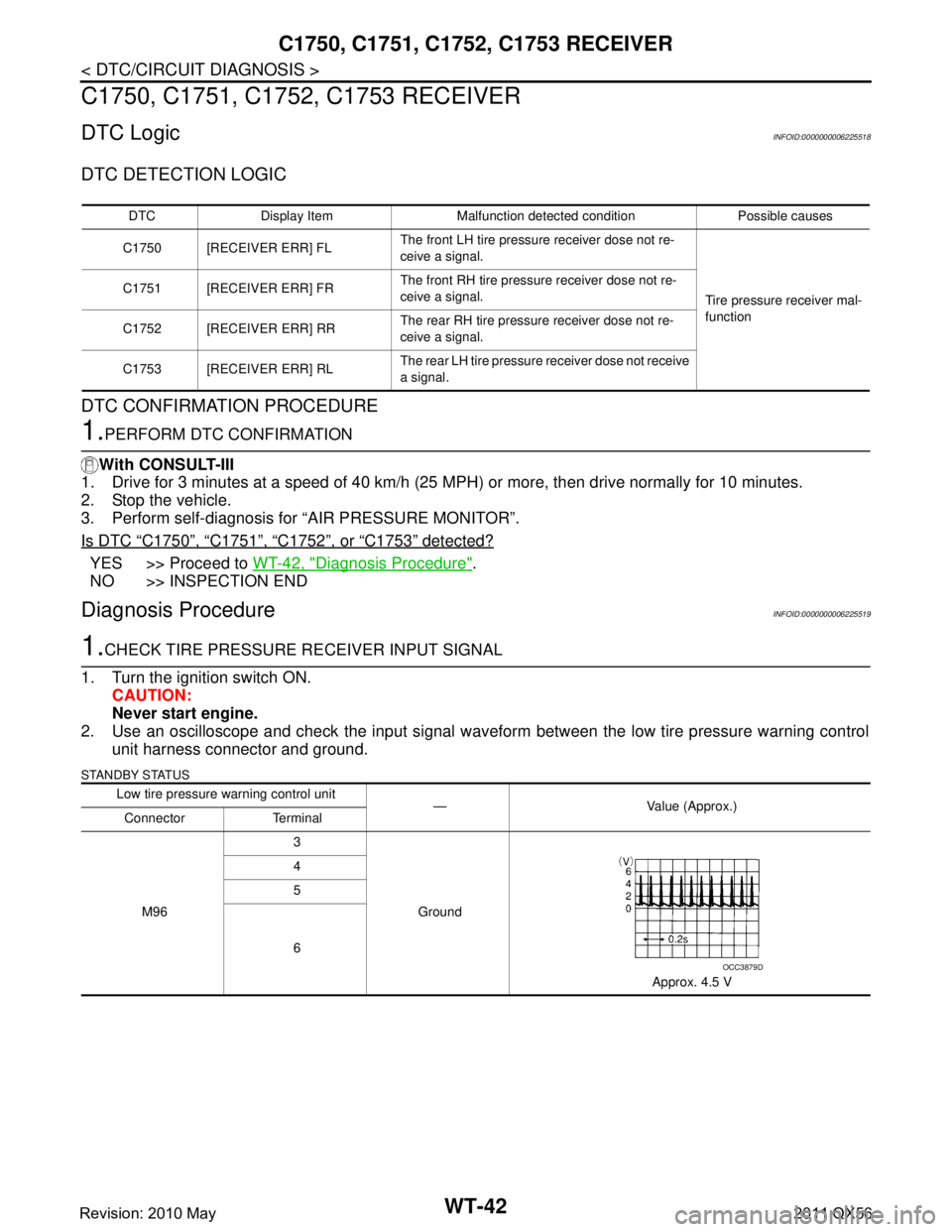
1.CHECK TIRE PRESSURE RE CEIVER INPUT SIGNAL
1. Turn the ignition switch ON. CAUTION:
Never start engine.
2. Use an oscilloscope and check the input signal waveform between the low tire pressure warning control unit harness connector and ground.
STANDBY STATUS
DTC Display Item Malfunction detected condition Possible causes
C1750 [RECEIVER ERR] FL The front LH tire pressure receiver dose not re-
ceive a signal.
Tire pressure receiver mal-
function
C1751 [RECEIVER ERR] FR
The front RH tire pressure receiver dose not re-
ceive a signal.
C1752 [RECEIVER ERR] RR The rear RH tire pressure receiver dose not re-
ceive a signal.
C1753 [RECEIVER ERR] RL The rear LH tire pressure
receiver dose not receive
a signal.
Low tire pressure warning control unit
— Value (Approx.)
Connector Terminal
M96 3
Ground
Approx. 4.5 V
4
5
6
OCC3879D
Revision: 2010 May2011 QX56
Page 5493 of 5598
C1750, C1751, C1752, C1753 RECEIVER
WT-43
< DTC/CIRCUIT DIAGNOSIS >
C
D F
G H
I
J
K L
M A
B
WT
N
O P
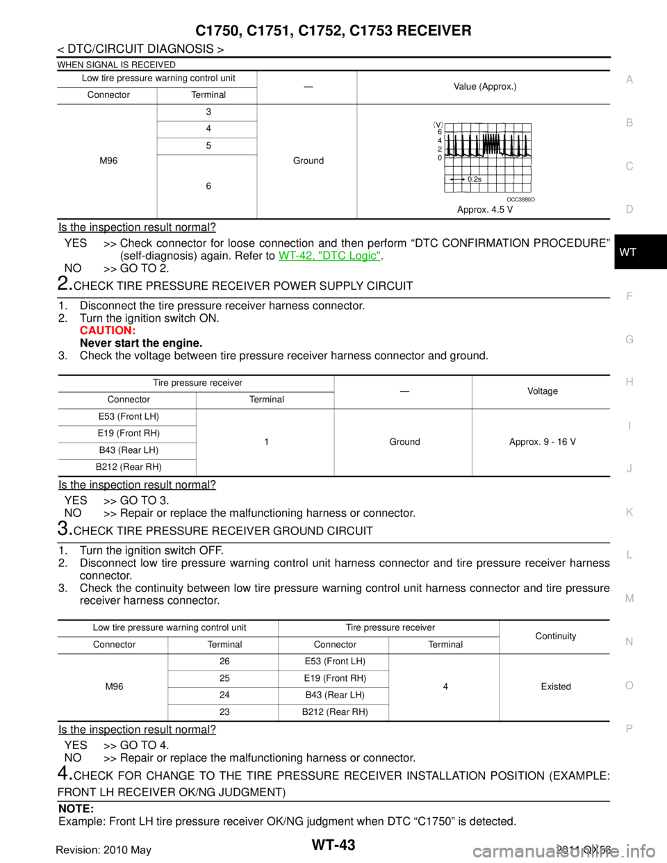
WHEN SIGNAL IS RECEIVED
Is the inspection result normal?
YES >> Check connector for loose connection and t hen perform “DTC CONFIRMATION PROCEDURE”
(self-diagnosis) again. Refer to WT-42, "
DTC Logic".
NO >> GO TO 2.
2.CHECK TIRE PRESSURE RECE IVER POWER SUPPLY CIRCUIT
1. Disconnect the tire pressure receiver harness connector.
2. Turn the ignition switch ON. CAUTION:
Never start the engine.
3. Check the voltage between tire pressure receiver harness connector and ground.
Is the inspection result normal?
YES >> GO TO 3.
NO >> Repair or replace the malfunctioning harness or connector.
3.CHECK TIRE PRESSURE RECEIVER GROUND CIRCUIT
1. Turn the ignition switch OFF.
2. Disconnect low tire pressure warning control unit harness connector and tire pressure receiver harness connector.
3. Check the continuity between low tire pressure warning control unit harness connector and tire pressure
receiver harness connector.
Is the inspection result normal?
YES >> GO TO 4.
NO >> Repair or replace the malfunctioning harness or connector.
4.CHECK FOR CHANGE TO THE TIRE PRESSURE RECEIVER INSTALLATION POSITION (EXAMPLE:
FRONT LH RECEIVER OK/NG JUDGMENT) NOTE:
Example: Front LH tire pressure receiver OK/NG judgment when DTC “C1750” is detected.
Low tire pressure warning control unit
— Value (Approx.)
Connector Terminal
M96 3
Ground
Approx. 4.5 V
4
5
6
OCC3880D
Tire pressu
re receiver
—Voltage
Connector Terminal
E53 (Front LH)
1 Ground Approx. 9 - 16 V
E19 (Front RH)
B43 (Rear LH)
B212 (Rear RH)
Low tire pressure wa rning control unit Tire pressure receiver
Continuity
Connector Terminal Connector Terminal
M96 26 E53 (Front LH)
4 Existed
25 E19 (Front RH)
24 B43 (Rear LH)
23 B212 (Rear RH)
Revision: 2010 May2011 QX56