2011 INFINITI QX56 tow
[x] Cancel search: towPage 3451 of 5598
![INFINITI QX56 2011 Factory Service Manual
LAN
SYSTEMLAN-31
< SYSTEM DESCRIPTION > [CAN]
C
D
E
F
G H
I
J
K L
B A
O P
N
Meter display signal
TR
RT
Oil pressure switch signal TR
RT
Position light request signal T R R
Rear fog light status signa INFINITI QX56 2011 Factory Service Manual
LAN
SYSTEMLAN-31
< SYSTEM DESCRIPTION > [CAN]
C
D
E
F
G H
I
J
K L
B A
O P
N
Meter display signal
TR
RT
Oil pressure switch signal TR
RT
Position light request signal T R R
Rear fog light status signa](/manual-img/42/57033/w960_57033-3450.png)
LAN
SYSTEMLAN-31
< SYSTEM DESCRIPTION > [CAN]
C
D
E
F
G H
I
J
K L
B A
O P
N
Meter display signal
TR
RT
Oil pressure switch signal TR
RT
Position light request signal T R R
Rear fog light status signal T R
Rear window defogger con-
trol signal TR
RT
Sleep wake up signal T R R R R R R
Starter control relay signal T R
Starter relay status signal TRR
RT
Starting mode signal T R
Steering lock relay signal TRR
RT
Theft warning horn request
signal TR
Turn indicator signal R T R R
A/C display signal R T
A/C ON signal R T
Ambient temperature signal T R
Blower fan ON signal R T
Distance to empty signal R T
Fuel level low warning sig-
nal RT
Fuel level sensor signal R T
Manual mode shift down
signal RT
Manual mode shift up sig-
nal RT
Manual mode signal R T
Non-manual mode signal R T
Odometer signal R T
Parking brake switch signal R R T R R
Sleep-ready signal RT
RT
RT
Tow mode switch signal R T
Wake up signal RT
RT
Steering angle sensor mal-
function signal RR T R R
Steering angle sensor sig-
nal RR RR T R R
Steering angle speed signal R T R R Signal name
ECM
4WD
ABS
TCM
A-BAG AFS
AV
BCM
CGW
HVAC M&A
STRG
TPMS
IPDM-E
ADPPSB
E-SUS ICC
PWBD
Revision: 2010 May2011 QX56
Page 3676 of 5598
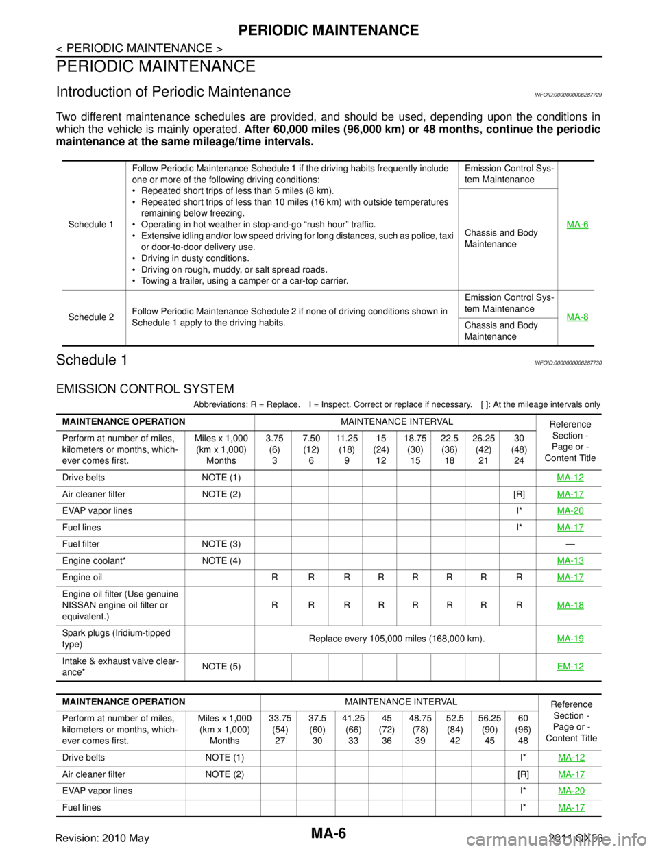
MA-6
< PERIODIC MAINTENANCE >
PERIODIC MAINTENANCE
PERIODIC MAINTENANCE
Introduction of Periodic MaintenanceINFOID:0000000006287729
Two different maintenance schedules are provided, and should be used, depending upon the conditions in
which the vehicle is mainly operated. After 60,000 miles (96,000 km) or 48 months, continue the periodic
maintenance at the same mileage/time intervals.
Schedule 1INFOID:0000000006287730
EMISSION CONTROL SYSTEM
Abbreviations: R = Replace. I = Inspec t. Correct or replace if necessary. [ ]: At the mileage intervals only
Schedule 1Follow Periodic Maintenance Schedule 1 if the driving habits frequently include
one or more of the following driving conditions:
Repeated short trips of less than 5 miles (8 km).
Repeated short trips of less than 10 miles (16 km) with outside temperatures
remaining below freezing.
Operating in hot weather in stop-and-go “rush hour” traffic.
Extensive idling and/or low speed driving for long distances, such as police, taxi
or door-to-door delivery use.
Driving in dusty conditions.
Driving on rough, muddy, or salt spread roads.
Towing a trailer, using a camper or a car-top carrier. Emission Control Sys-
tem Maintenance
MA-6Chassis and Body
Maintenance
Schedule 2 Follow Periodic Maintenance Schedule 2 if none of driving conditions shown in
Schedule 1 apply to the driving habits. Emission Control Sys-
tem Maintenance
MA-8
Chassis and Body
Maintenance
MAINTENANCE OPERATION MAINTENANCE INTERVAL
Reference
Section -
Page or -
Content Title
Perform at number of miles,
kilometers or months, which-
ever comes first. Miles x 1,000
(km x 1,000) Months 3.75
(6)3 7.50
(12) 6 11 . 2 5
(18) 9 15
(24) 12 18.75
(30)15 22.5
(36) 18 26.25
(42)21 30
(48) 24
Drive belts NOTE (1) MA-12
Air cleaner filter NOTE (2) [R]MA-17
EVAP vapor linesI*MA-20
Fuel lines I*MA-17
Fuel filter NOTE (3) —
Engine coolant* NOTE (4) MA-13
Engine oil R R R R R R R RMA-17
Engine oil filter (Use genuine
NISSAN engine oil filter or
equivalent.)R R RRRRR R
MA-18
Spark plugs (Iridium-tipped
type)Replace every 105,000 miles (168,000 km).
MA-19
Intake & exhaust valve clear-
ance*NOTE (5)
EM-12
MAINTENANCE OPERATIONMAINTENANCE INTERVAL
Reference
Section -
Page or -
Content Title
Perform at number of miles,
kilometers or months, which-
ever comes first. Miles x 1,000
(km x 1,000) Months 33.75
(54)27 37.5
(60) 30 41.25
(66)33 45
(72) 36 48.75
(78)39 52.5
(84) 42 56.25
(90)45 60
(96) 48
Drive belts NOTE (1) I* MA-12
Air cleaner filter NOTE (2) [R]MA-17
EVAP vapor linesI*MA-20
Fuel lines I*MA-17
Revision: 2010 May2011 QX56
Page 3678 of 5598
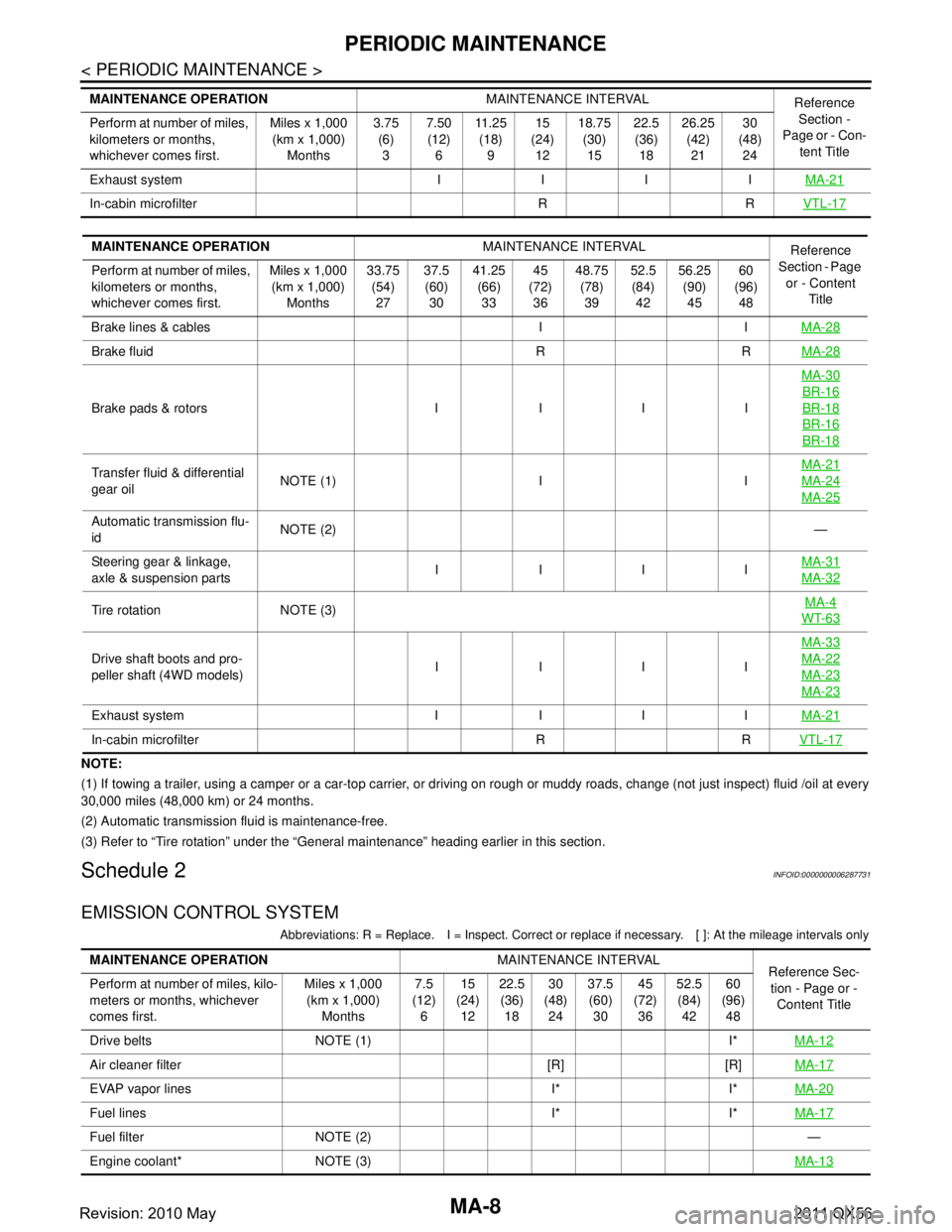
MA-8
< PERIODIC MAINTENANCE >
PERIODIC MAINTENANCE
NOTE:
(1) If towing a trailer, using a camper or a car-top carrier, or driving on rough or muddy roads, change (not just inspect) fluid /oil at every
30,000 miles (48,000 km) or 24 months.
(2) Automatic transmission fluid is maintenance-free.
(3) Refer to “Tire rotation” unde r the “General maintenance” heading earlier in this section.
Schedule 2INFOID:0000000006287731
EMISSION CONTROL SYSTEM
Abbreviations: R = Replace. I = Inspec t. Correct or replace if necessary. [ ]: At the mileage intervals only
Exhaust system I I I I MA-21
In-cabin microfilter R RVTL-17
MAINTENANCE OPERATIONMAINTENANCE INTERVAL
Reference
Section -
Page or - Con- tent Title
Perform at number of miles,
kilometers or months,
whichever comes first. Miles x 1,000
(km x 1,000)
Months 3.75
(6)
3 7.50
(12)
6 11 . 2 5
(18)
9 15
(24)
12 18.75
(30)
15 22.5
(36)
18 26.25
(42)
21 30
(48)
24
MAINTENANCE OPERATION MAINTENANCE INTERVAL
Reference
Section - Page
or - Content Title
Perform at number of miles,
kilometers or months,
whichever comes first. Miles x 1,000
(km x 1,000) Months 33.75
(54)27 37.5
(60) 30 41.25
(66)33 45
(72) 36 48.75
(78)39 52.5
(84) 42 56.25
(90)45 60
(96) 48
Brake lines & cables I I MA-28
Brake fluid R RMA-28
Brake pads & rotors I I I IMA-30
BR-16
BR-18
BR-16
BR-18
Transfer fluid & differential
gear oil
NOTE (1) I I MA-21MA-24
MA-25
Automatic transmission flu-
id
NOTE (2)
—
Steering gear & linkage,
axle & suspension parts IIII
MA-31
MA-32
Tire rotation NOTE (3) MA-4WT-63
Drive shaft boots and pro-
peller shaft (4WD models)IIII MA-33MA-22
MA-23
MA-23
Exhaust system I I I I
MA-21
In-cabin microfilter R RVTL-17
MAINTENANCE OPERATIONMAINTENANCE INTERVAL
Reference Sec-
tion - Page or -
Content Title
Perform at number of miles, kilo-
meters or months, whichever
comes first. Miles x 1,000
(km x 1,000)
Months 7.5
(12)
6 15
(24)
12 22.5
(36)
18 30
(48)
24 37.5
(60)
30 45
(72)
36 52.5
(84)
42 60
(96)
48
Drive belts NOTE (1) I* MA-12
Air cleaner filter [R] [R]MA-17
EVAP vapor lines I* I*MA-20
Fuel lines I* I*MA-17
Fuel filter NOTE (2) —
Engine coolant* NOTE (3) MA-13
Revision: 2010 May2011 QX56
Page 3756 of 5598
MWI
SYSTEMMWI-13
< SYSTEM DESCRIPTION >
C
DE
F
G H
I
J
K L
M B A
O P
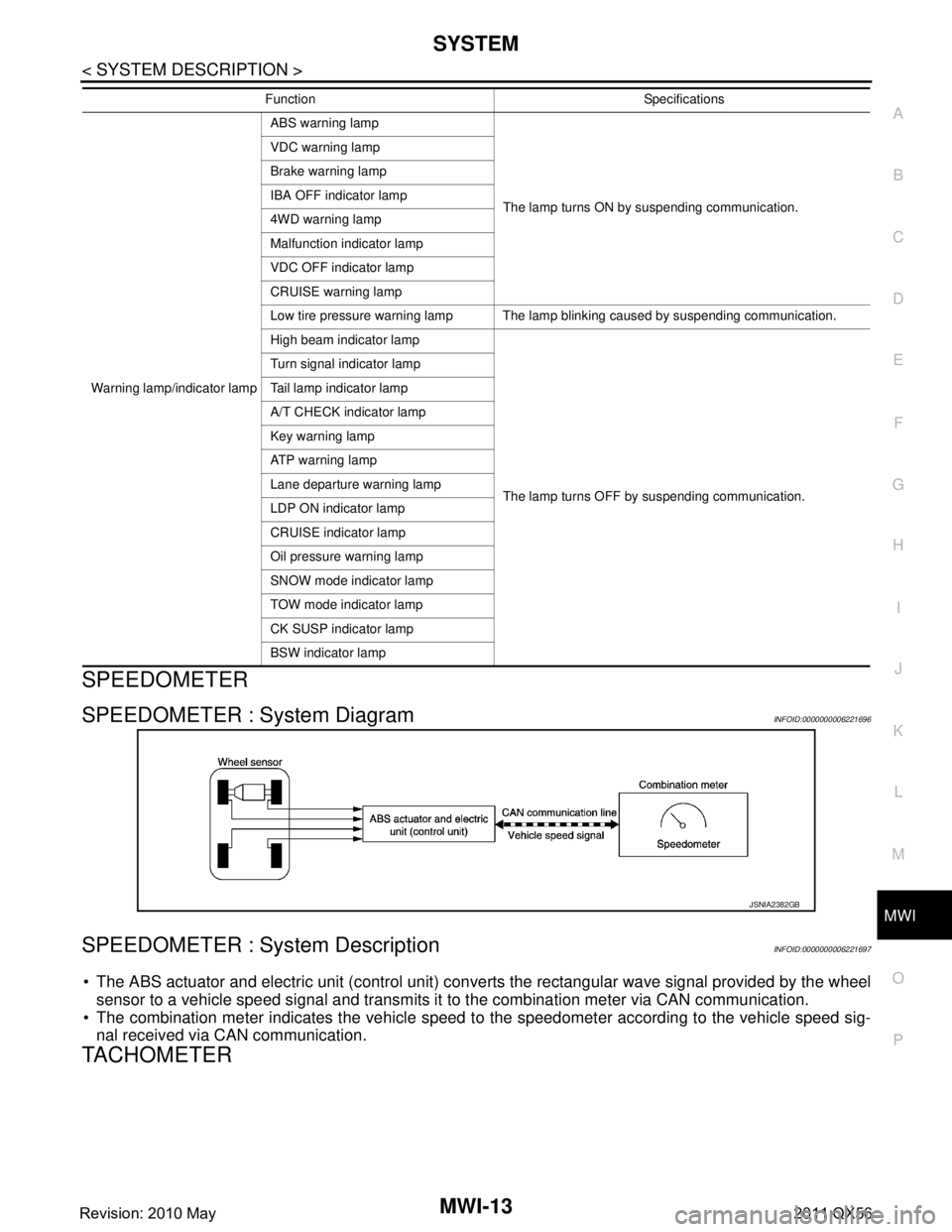
SPEEDOMETER
SPEEDOMETER : System DiagramINFOID:0000000006221696
SPEEDOMETER : System DescriptionINFOID:0000000006221697
The ABS actuator and electric unit (control unit) conv erts the rectangular wave signal provided by the wheel
sensor to a vehicle speed signal and transmits it to the combination meter via CAN communication.
The combination meter indicates the vehicle speed to the speedometer according to the vehicle speed sig-
nal received via CAN communication.
TACHOMETER
Warning lamp/indicator lamp ABS warning lamp
The lamp turns ON by suspending communication.
VDC warning lamp
Brake warning lamp
IBA OFF indicator lamp
4WD warning lamp
Malfunction indicator lamp
VDC OFF indicator lamp
CRUISE warning lamp
Low tire pressure warning lamp The lamp blinking caused by suspending communication.
High beam indicator lamp
The lamp turns OFF by suspending communication.
Turn signal indicator lamp
Tail lamp indicator lamp
A/T CHECK indicator lamp
Key warning lamp
AT P w a r n i n g l a m p
Lane departure warning lamp
LDP ON indicator lamp
CRUISE indicator lamp
Oil pressure warning lamp
SNOW mode indicator lamp
TOW mode indicator lamp
CK SUSP indicator lamp
BSW indicator lamp
Function Specifications
JSNIA2382GB
Revision: 2010 May2011 QX56
Page 3776 of 5598
MWI
DIAGNOSIS SYSTEM (COMBINATION METER)
MWI-33
< SYSTEM DESCRIPTION >
C
D E
F
G H
I
J
K L
M B A
O P
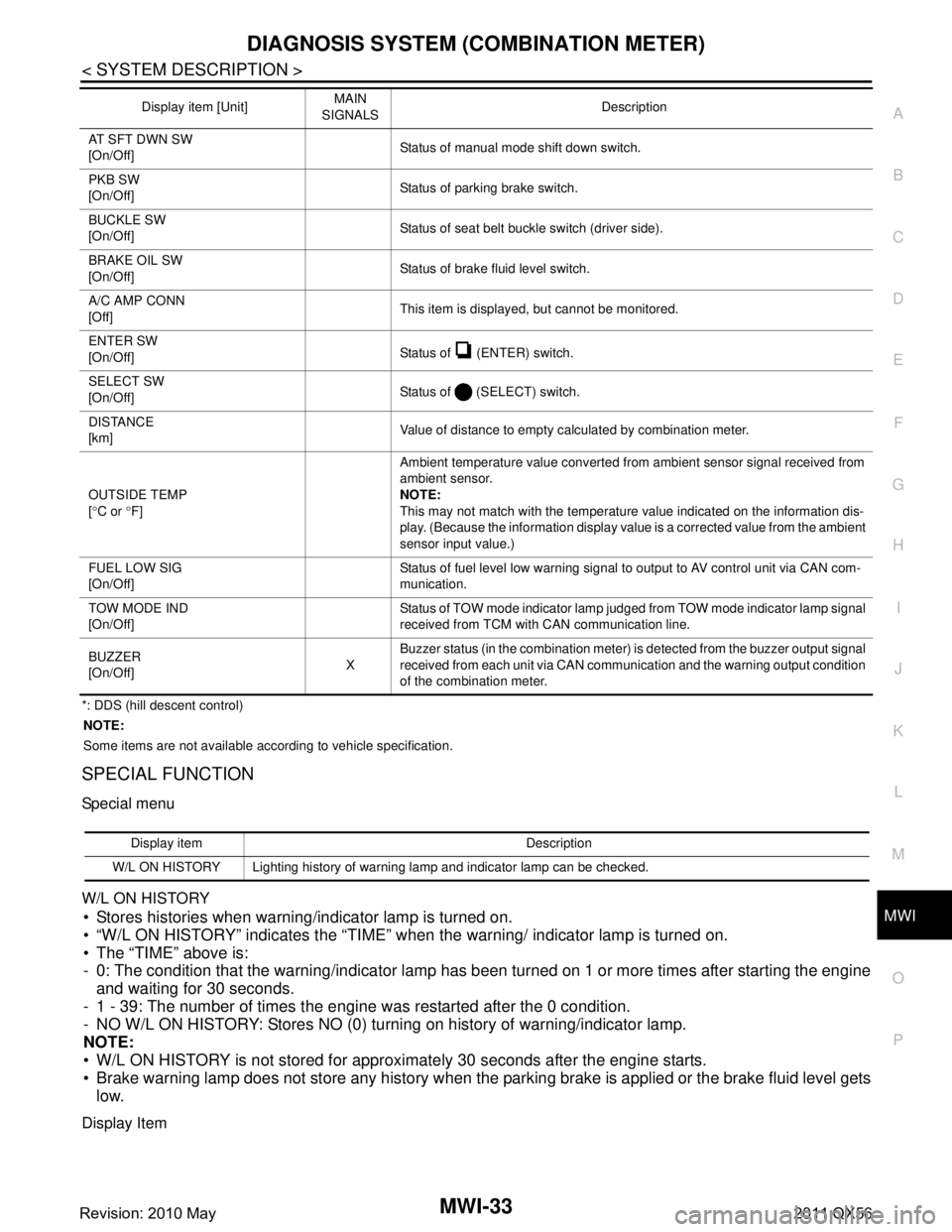
*: DDS (hill descent control) NOTE:
Some items are not available according to vehicle specification.
SPECIAL FUNCTION
Special menu
W/L ON HISTORY
Stores histories when warning/indicator lamp is turned on.
“W/L ON HISTORY” indicates the “TIME” when the warning/ indicator lamp is turned on.
The “TIME” above is:
- 0: The condition that the warning/indicator lamp has been turned on 1 or more times after starting the engine and waiting for 30 seconds.
- 1 - 39: The number of times the engine was restarted after the 0 condition.
- NO W/L ON HISTORY: Stores NO (0) turning on history of warning/indicator lamp.
NOTE:
W/L ON HISTORY is not stored for approximately 30 seconds after the engine starts.
Brake warning lamp does not store any history when the parking brake is applied or the brake fluid level gets
low.
Display Item
AT SFT DWN SW
[On/Off] Status of manual mode shift down switch.
PKB SW
[On/Off] Status of parking brake switch.
BUCKLE SW
[On/Off] Status of seat belt buckle switch (driver side).
BRAKE OIL SW
[On/Off] Status of brake fluid level switch.
A/C AMP CONN
[Off] This item is displayed, but cannot be monitored.
ENTER SW
[On/Off] Status of (ENTER) switch.
SELECT SW
[On/Off] Status of (SELECT) switch.
DISTANCE
[km] Value of distance to empty calculated by combination meter.
OUTSIDE TEMP
[ ° C or °F] Ambient temperature value converted from ambient sensor signal received from
ambient sensor.
NOTE:
This may not match with the temperature value indicated on the information dis-
play. (Because the information display value is a corrected value from the ambient
sensor input value.)
FUEL LOW SIG
[On/Off] Status of fuel level low warning signal to output to AV control unit via CAN com-
munication.
TOW MODE IND
[On/Off] Status of TOW mode indicator lamp judged from TOW mode indicator lamp signal
received from TCM with CAN communication line.
BUZZER
[On/Off] XBuzzer status (in the combination meter) is detected from the buzzer output signal
received from each unit via CAN communication and the warning output condition
of the combination meter.
Display item [Unit]
MAIN
SIGNALS Description
Display item Description
W/L ON HISTORY Lighting history of warning lamp and indicator lamp can be checked.
Revision: 2010 May2011 QX56
Page 3782 of 5598
MWI
COMBINATION METERMWI-39
< ECU DIAGNOSIS INFORMATION >
C
DE
F
G H
I
J
K L
M B A
O P
NOTE:
Some items are not available according to vehicle specification.
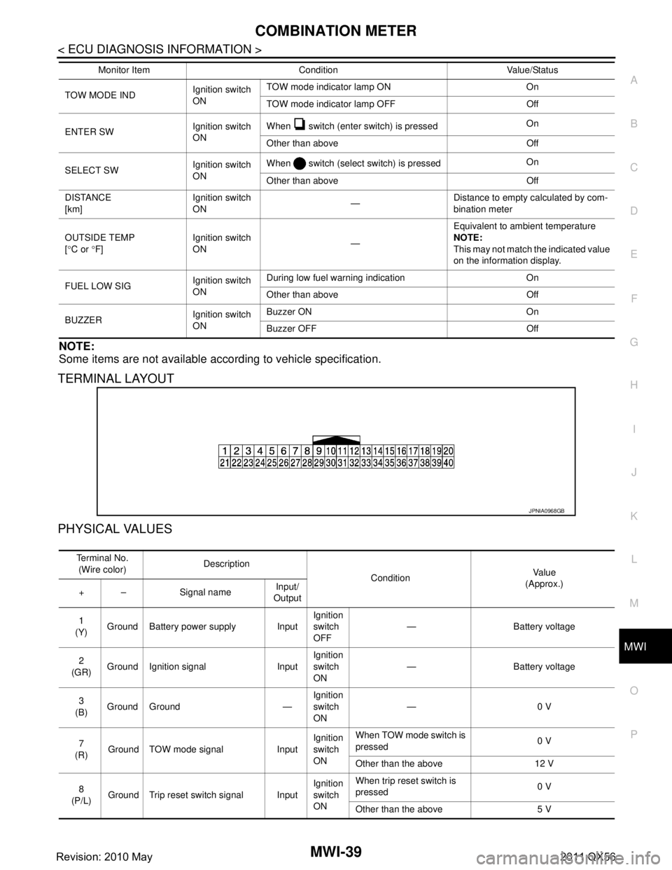
TERMINAL LAYOUT
PHYSICAL VALUES
TOW MODE IND Ignition switch
ONTOW mode indicator lamp ON On
TOW mode indicator lamp OFF Off
ENTER SW Ignition switch
ONWhen switch (enter switch) is pressed
On
Other than above Off
SELECT SW Ignition switch
ONWhen switch (select switch) is pressed
On
Other than above Off
DISTANCE
[km] Ignition switch
ON
—Distance to empty calculated by com-
bination meter
OUTSIDE TEMP
[ ° C or °F] Ignition switch
ON
—Equivalent to ambient temperature
NOTE:
This may not match the indicated value
on the information display.
FUEL LOW SIG Ignition switch
ONDuring low fuel warning indication On
Other than above Off
BUZZER Ignition switch
ONBuzzer ON On
Buzzer OFF Off
Monitor Item Condition Value/Status
JPNIA0968GB
Te r m i n a l N o .
(Wire color) Description
ConditionVa l u e
(Approx.)
+ – Signal name Input/
Output
1
(Y) Ground Battery power supply Input Ignition
switch
OFF— Battery voltage
2
(GR) Ground Ignition signal Input Ignition
switch
ON
— Battery voltage
3
(B) Ground Ground — Ignition
switch
ON—0 V
7
(R) Ground TOW mode signal Input Ignition
switch
ONWhen TOW mode switch is
pressed
0 V
Other than the above 12 V
8
(P/L) Ground Trip reset switch signal Input Ignition
switch
ONWhen trip reset switch is
pressed
0 V
Other than the above 5 V
Revision: 2010 May2011 QX56
Page 3786 of 5598
MWI
COMBINATION METERMWI-43
< ECU DIAGNOSIS INFORMATION >
C
DE
F
G H
I
J
K L
M B A
O P
DTC IndexINFOID:0000000006221723
Warning lamp/indicator lamp ABS warning lamp
The lamp turns ON by suspending communication.
VDC warning lamp
Brake warning lamp
IBA OFF indicator lamp
4WD warning lamp
Malfunction indicator lamp
VDC OFF indicator lamp
CRUISE warning lamp
Low tire pressure warning lamp The lamp blinking caused by suspending communication.
High beam indicator lamp
The lamp turns OFF by suspending communication.
Turn signal indicator lamp
Tail lamp indicator lamp
A/T CHECK indicator lamp
Key warning lamp
AT P w a r n i n g l a m p
Lane departure warning lamp
LDP ON indicator lamp
CRUISE indicator lamp
Oil pressure warning lamp
SNOW mode indicator lamp
TOW mode indicator lamp
CK SUSP indicator lamp
BSW indicator lamp
Function Specifications
Display contents of CONSULT-III Diagnostic item is detected when... Refer to
CAN COMM CIRCUIT
[U1000] When combination meter is not transmitting or receiving CAN communication signal
for 2 seconds or more. MWI-59,
"Diagnosis
Procedure"
CONTROL UNIT (CAN)
[U1010]
When detecting error during the initial diagnosis of the CAN controller of combina-
tion meter. MWI-60, "Diagnosis
Procedure"
VEHICLE SPEED
[B2205]
The abnormal vehicle speed signal is input from the ABS actuator and electric unit
(control unit) for
2 seconds or more. MWI-61, "Diagnosis
Procedure"
ENGINE SPEED
[B2267]
If ECM continuously transmits abnormal engine speed signals for 2 seconds or
more. MWI-62, "Diagnosis
Procedure"
WATER TEMP
[B2268]
If ECM continuously transmits abnormal engine coolant temperature signals for 60
seconds or more. MWI-63, "Diagnosis
Procedure"
Revision: 2010 May2011 QX56
Page 4231 of 5598
INSPECTION AND ADJUSTMENTRF-17
< BASIC INSPECTION >
C
DE
F
G H
I
J
L
M A
B
RF
N
O P
INSPECTION AND ADJUSTMENT
ADDITIONAL SERVICE WHEN REPLACING CONTROL UNIT
ADDITIONAL SERVICE WHEN REPL ACING CONTROL UNIT : Description
INFOID:0000000006141230
MEMORY RESET PROCEDURE
1. Please observe the following instructi ons at confirming the sunroof operation.
NOTE:
Do not disconnect the electronic power while the sunroof is operating or within 5 seconds after the sunroof
stops (to wipe-out the memory of lid position and operating friction).
2. Initialization of system should be conducted after the following conditions.
When the sunroof motor is changed.
When the sunroof does not operate normally. (Incomplete initialization conditions)
ADDITIONAL SERVICE WHEN REPLACING CONTROL UNIT : Special Repair Re-
quirement
INFOID:0000000006141231
INITIALIZATION PROCEDURE
If the sunroof does not close or open automatically, us e the following procedure to return sunroof operation to
normal.
1. Press the tilt up switch and start the tilt up operation.
2. Release the tilt up switch once, press the tilt up switch again, press and hold the switch until lid pops up.
3. The glass lid moves slight toward tilt up direction then stop. (Press and hold the switch during this opera- tion)
4. Release the switch again, and press the tilt up s witch within the first 10 seconds. (Press and hold the
switch)
5. After 4 seconds, the glass lid will be automatically operated in sequence of tilt down, slide open and slide
close.
6. After the glass lid stops, release the switch 0.5 second later. (Press and hold the switch during this opera-
tion)
7. If slide switch operates normally, this initialization is done.
ANTI-PINCH FUNCTION
1. Full open the sunroof.
2. Place a wooden piece (wooden hammer handle, etc.) at near fully closed position.
3. Close the sunroof completely with auto-slide close.
Check that sunroof lowers for approximately 150 mm (5 .91in) or 2 seconds with out pinching a wooden piece
and stops.
CAUTION:
Never check with hands and other part of body because they may be pinched. Never get pinched.
Depending on environment and driving conditions, if a similar impact or lord is applied to the sun-
roof it may lower.
Check that auto-slide operates before inspect ion when system initialization is performed.
Perform initial setting when auto-slide operatio n or anti-pinch function does not operate normally.
Revision: 2010 May2011 QX56