Page 5430 of 5598

WCS-26
< ECU DIAGNOSIS INFORMATION >
COMBINATION METER
NOTE:
Some items are not available according to vehicle specification.
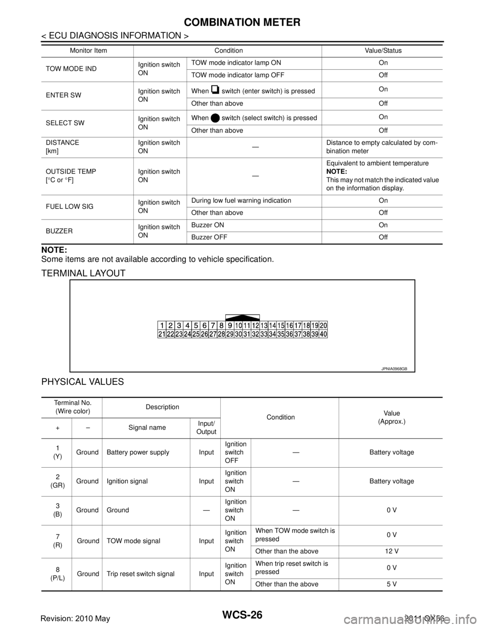
TERMINAL LAYOUT
PHYSICAL VALUES
TOW MODE INDIgnition switch
ONTOW mode indicator lamp ON On
TOW mode indicator lamp OFF Off
ENTER SW Ignition switch
ONWhen switch (enter switch) is pressed
On
Other than above Off
SELECT SW Ignition switch
ONWhen switch (select switch) is pressed
On
Other than above Off
DISTANCE
[km] Ignition switch
ON
—Distance to empty calculated by com-
bination meter
OUTSIDE TEMP
[ ° C or °F] Ignition switch
ON
—Equivalent to ambient temperature
NOTE:
This may not match the indicated value
on the information display.
FUEL LOW SIG Ignition switch
ONDuring low fuel warning indication On
Other than above Off
BUZZER Ignition switch
ONBuzzer ON On
Buzzer OFF Off
Monitor Item Condition Value/Status
JPNIA0968GB
Te r m i n a l N o .
(Wire color) Description
ConditionVa l u e
(Approx.)
+ – Signal name Input/
Output
1
(Y) Ground Battery power supply Input Ignition
switch
OFF— Battery voltage
2
(GR) Ground Ignition signal Input Ignition
switch
ON
— Battery voltage
3
(B) Ground Ground — Ignition
switch
ON—0 V
7
(R) Ground TOW mode signal Input Ignition
switch
ONWhen TOW mode switch is
pressed
0 V
Other than the above 12 V
8
(P/L) Ground Trip reset switch signal Input Ignition
switch
ONWhen trip reset switch is
pressed
0 V
Other than the above 5 V
Revision: 2010 May2011 QX56
Page 5434 of 5598

WCS-30
< ECU DIAGNOSIS INFORMATION >
COMBINATION METER
DTC Index
INFOID:0000000006222690
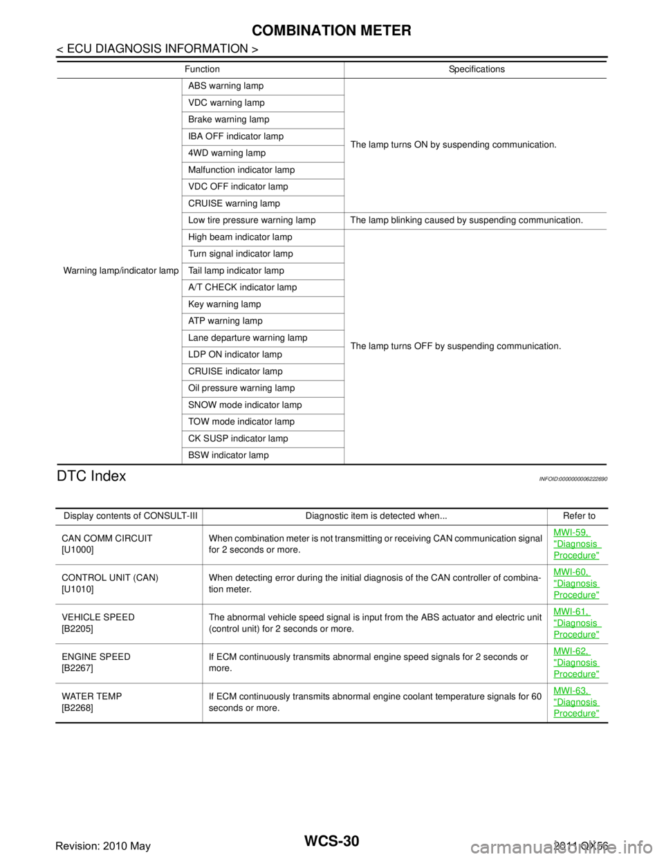
Warning lamp/indicator lamp ABS warning lamp
The lamp turns ON by suspending communication.
VDC warning lamp
Brake warning lamp
IBA OFF indicator lamp
4WD warning lamp
Malfunction indicator lamp
VDC OFF indicator lamp
CRUISE warning lamp
Low tire pressure warning lamp The lamp blinking caused by suspending communication.
High beam indicator lamp
The lamp turns OFF by suspending communication.
Turn signal indicator lamp
Tail lamp indicator lamp
A/T CHECK indicator lamp
Key warning lamp
ATP warning lamp
Lane departure warning lamp
LDP ON indicator lamp
CRUISE indicator lamp
Oil pressure warning lamp
SNOW mode indicator lamp
TOW mode indicator lamp
CK SUSP indicator lamp
BSW indicator lamp
Function Specifications
Display contents of CONSULT-III Diagnostic item is detected when... Refer to
CAN COMM CIRCUIT
[U1000] When combination meter is not transmitting or receiving CAN communication signal
for 2 seconds or more. MWI-59,
"Diagnosis
Procedure"
CONTROL UNIT (CAN)
[U1010]
When detecting error during the initial diagnosis of the CAN controller of combina-
tion meter. MWI-60, "Diagnosis
Procedure"
VEHICLE SPEED
[B2205]
The abnormal vehicle sp
eed signal is input from the ABS actuator and electric unit
(control unit) for 2 seconds or more. MWI-61, "Diagnosis
Procedure"
ENGINE SPEED
[B2267]
If ECM continuously transmits abnormal engine speed signals for 2 seconds or
more. MWI-62, "Diagnosis
Procedure"
WATER TEMP
[B2268]
If ECM continuously transmits abnormal engine coolant temperature signals for 60
seconds or more. MWI-63, "Diagnosis
Procedure"
Revision: 2010 May2011 QX56
Page 5583 of 5598
WW-64
< REMOVAL AND INSTALLATION >
FRONT WASHER NOZZLE AND TUBE
Removal and Installation
INFOID:0000000006220406
REMOVAL
1. Remove cowl top cover. Refer to EXT-21, "Removal and Installation".
2. Disconnect front washer tube from front washer nozzle.
3. While pressing pawl (A) on the cowl top cover front side of front washer nozzle (1), remove front washer nozzle from cowl top
cover.
INSTALLATION
Note the following item, and then install in the reverse order of removal.
CAUTION:
The spray positions differ, check that left and right nozzles are installed correctly.
Inspection and AdjustmentINFOID:0000000006220407
INSPECTION
Check valve Inspection
Check that air can pass through the hose by blowing forward (toward
the nozzle), and check that air cannot pass through by sucking.
ADJUSTMENT
Washer Nozzle Spray Position Adjustment
Adjust spray positions to match the positions shown in the figure.
JPLIA0871ZZ
JPLIA0685ZZ
Revision: 2010 May2011 QX56
Page 5587 of 5598
WW-68
< REMOVAL AND INSTALLATION >
FRONT WIPER BLADE
FRONT WIPER BLADE
Exploded ViewINFOID:0000000006220411
Removal and InstallationINFOID:0000000006220412
REMOVAL
1. Push up the lever (A) of wiper blade (1), while sliding wiperblade toward the direction of the arrow, to remove it from wiper
arm (2).
CAUTION:
Be careful not to drop the wi per blade onto the windshield
glass.
INSTALLATION
1. Install wiper blade into wiper arm.
2. Install wiper arm.
ReplacementINFOID:0000000006220413
1. Hold the rip of old wiper refill (1) at the rear end of the wiper blade with long-nose pliers, and pull out the wiper refill to the
direction (A).
1. Wiper refill 2. Wiper blade 3. Wiper arm
A. Wiper blade end B. Wiper blade tip
JMLIA1127ZZ
JMLIA1044ZZ
JPLIA1583ZZ
Revision: 2010 May2011 QX56
Page 5588 of 5598

FRONT WIPER BLADEWW-69
< REMOVAL AND INSTALLATION >
C
DE
F
G H
I
J
K
M A
B
WW
N
O P
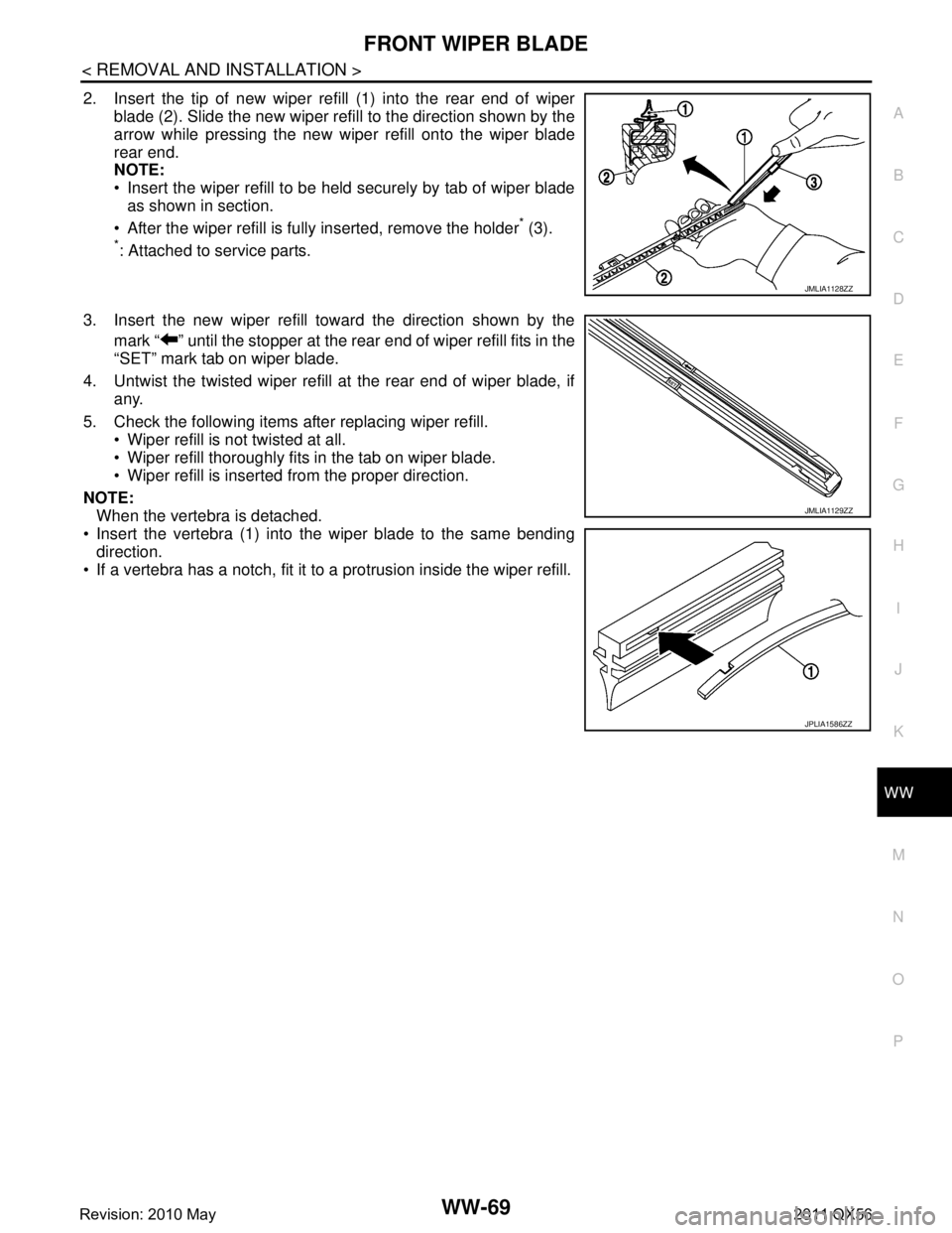
2. Insert the tip of new wiper refill (1) into the rear end of wiper blade (2). Slide the new wiper refill to the direction shown by the
arrow while pressing the new wiper refill onto the wiper blade
rear end.
NOTE:
Insert the wiper refill to be held securely by tab of wiper bladeas shown in section.
After the wiper refill is fully inserted, remove the holder
* (3).
*: Attached to service parts.
3. Insert the new wiper refill toward the direction shown by the mark “ ” until the stopper at the rear end of wiper refill fits in the
“SET” mark tab on wiper blade.
4. Untwist the twisted wiper refill at the rear end of wiper blade, if any.
5. Check the following items after replacing wiper refill. Wiper refill is not twisted at all.
Wiper refill thoroughly fits in the tab on wiper blade.
Wiper refill is inserted from the proper direction.
NOTE: When the vertebra is detached.
Insert the vertebra (1) into the wiper blade to the same bending direction.
If a vertebra has a notch, fit it to a protrusion inside the wiper refill.
JMLIA1128ZZ
JMLIA1129ZZ
JPLIA1586ZZ
Revision: 2010 May2011 QX56
Page 5597 of 5598
WW-78
< REMOVAL AND INSTALLATION >
REAR WASHER NOZZLE AND TUBE
3. Remove the screws fixing rear washer nozzle (2) to high-mounted stop lamp cover (3).
4. Disconnect the rear washer tube (1) from the rear washer noz-
zle.
INSTALLATION
Install in the reverse order of removal.
Inspection and AdjustmentINFOID:0000000006220427
INSPECTION
Washer Nozzle Inspection
Check that air can pass through the hose by blowing forward (toward
the nozzle), and check that air cannot pass through by sucking.
ADJUSTMENT
Washer Nozzle Spray Position adjustment
Adjust spray positions to match the positions shown in the figure.
Unit: mm (in)
JMLIA0943ZZ
JMLIA1131ZZ
1 : Black printed frame line
L : Length H : Height φ: Spray area
40.7 (1.60) 3.9 (0.15) 30 (1.18)
JMLIA1101ZZ
Revision: 2010 May2011 QX56