Page 3054 of 5598
REAR DOOR GLASSGW-25
< REMOVAL AND INSTALLATION >
C
DE
F
G H
I
J
L
M A
B
GW
N
O P
19. Slide partition glass toward the vehicle and remove it as shown in the figure.
INSTALLATION
Install in the reverse order of removal.
Inspection and AdjustmentINFOID:0000000006220831
SYSTEM INITIALIZATION
Initialize the system if any of t he following work has been done. Refer to PWC-31, "Description".
Initialization
Follow the steps below after installing each component to the vehicle. Refer to PWC-31, "Work Procedure".
FITTING INSPECTION
Check that the glass is fit securely into the sash groove.
Lower the glass slightly [approximately 10 to 20 mm (0.394 to 0.787 in)], and check that the clearance to the
sash is parallel. Loosen the regulator mounting bolts, guide rail mounting bolts, and glass and guide rail
mounting bolts to correct the glass position if the clearance between the glass and sash is not parallel.
JMKIA5274ZZ
Revision: 2010 May2011 QX56
Page 3194 of 5598
HAC-88
< DTC/CIRCUIT DIAGNOSIS >[AUTOMATIC AIR CONDITIONING]
B2630, B2631 SUNLOAD
SENSOR (DRIVER SIDE)
NOTE:
When checking indoors, use a lamp of approximately 60 W. Move the lamp towards and away from the
sensor to check.
The sunload amount produced by direct sunshine in fa ir weather is equivalent to approximately 0.770
kW/m
2 (662 kcal/m2·h).
Is the inspection result normal?
YES >> INSPECTION END
NO >> Replace sunload sensor. Refer to HAC-149, "
Removal and Installation".
+
−
A/C auto amp.
Connector Terminal M50 9 Ground
JPIIA1659GB
Revision: 2010 May2011 QX56
Page 3211 of 5598
B2667, B2668 SUNLOAD SENSOR (PASSENGER SIDE)
HAC-105
< DTC/CIRCUIT DIAGNOSIS > [AUTOMATIC AIR CONDITIONING]
C
D
E
F
G H
J
K L
M A
B
HAC
N
O P
NOTE:
When checking indoors, use a lamp of approximately 60 W. Move the lamp towards and away from the
sensor to check.
The sunload amount produced by direct sunshine in fa ir weather is equivalent to approximately 0.770
kW/m
2 (662 kcal/m2·h).
Is the inspection result normal?
YES >> INSPECTION END
NO >> Replace sunload sensor. Refer to HAC-149, "
Removal and Installation".
+
−
A/C auto amp.
Connector Terminal M50 29 Ground
JPIIA1659GB
Revision: 2010 May2011 QX56
Page 3339 of 5598

INL-72
< REMOVAL AND INSTALLATION >
FOOT LAMP
PASSENGER SIDE : Replacement
INFOID:0000000006288652
CAUTION:
Disconnect the battery cable from negative terminal or remove the fuse.
Never touch the glass of bulb directly by hand. Keep grease and other oily substaces away from it.
Never touch bulb by hand while it is lit or right after it is off.
Never leave bulb out of lamp reflector for a long ti me because dust, moisture smoke, etc. may affect
the performance of lamp. When replacing bu lb, be sure to replace it with a new one.
FOOT LAMP BULB (PASSENGER SIDE)
1. Remove instrument lower cover. Refer to IP-14, "Removal and Installation".
2. Rotate the bulb socket counterclockwise and unlock it.
3. Remove the bulb.
REAR FOOT LAMP
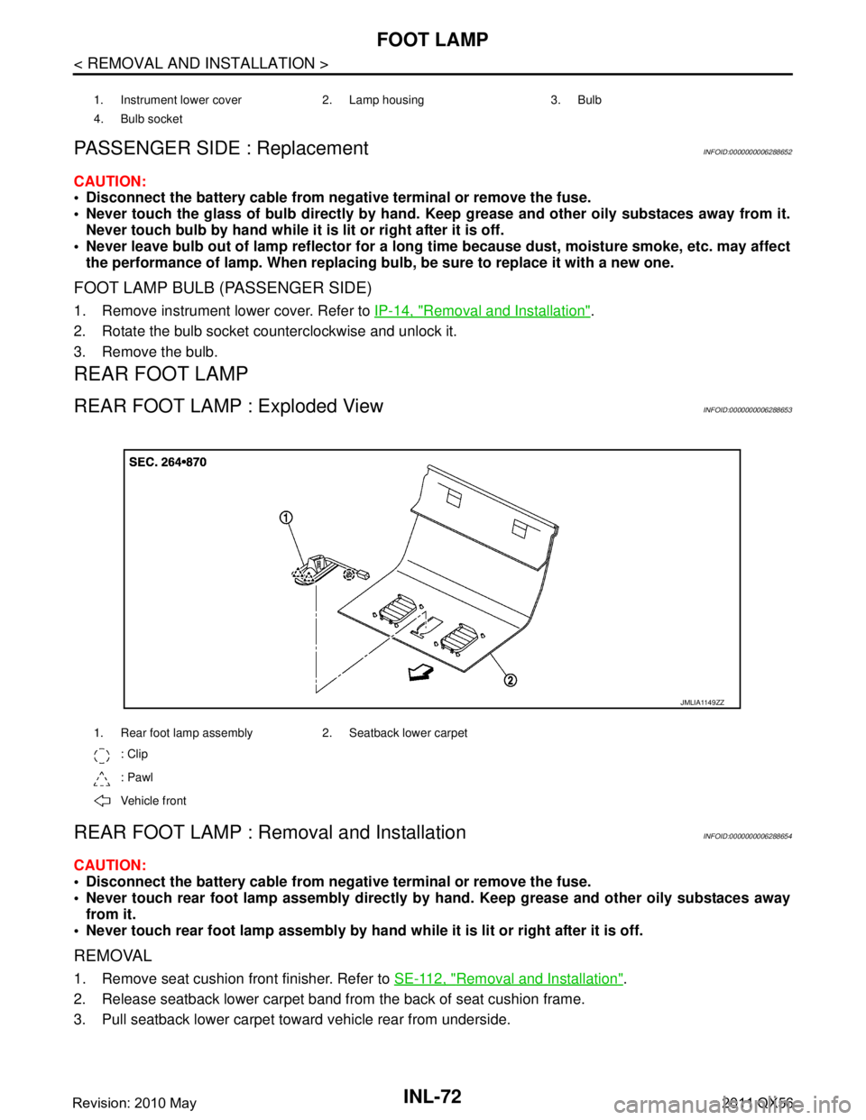
REAR FOOT LAMP : Exploded ViewINFOID:0000000006288653
REAR FOOT LAMP : Re moval and InstallationINFOID:0000000006288654
CAUTION:
Disconnect the battery cable from negative terminal or remove the fuse.
Never touch rear foot lamp assembly directly by hand. Keep grease and other oily substaces away
from it.
Never touch rear foot lamp assembly by hand while it is lit or right after it is off.
REMOVAL
1. Remove seat cushion front finisher. Refer to SE-112, "Removal and Installation".
2. Release seatback lower carpet band fr om the back of seat cushion frame.
3. Pull seatback lower carpet toward vehicle rear from underside.
1. Instrument lower cover 2. Lamp housing 3. Bulb
4. Bulb socket
1. Rear foot lamp assembly 2. Seatback lower carpet
: Clip
: Pawl
Vehicle front
JMLIA1149ZZ
Revision: 2010 May2011 QX56
Page 3410 of 5598

IP-20
< REMOVAL AND INSTALLATION >
INSTRUMENT PANEL ASSEMBLY
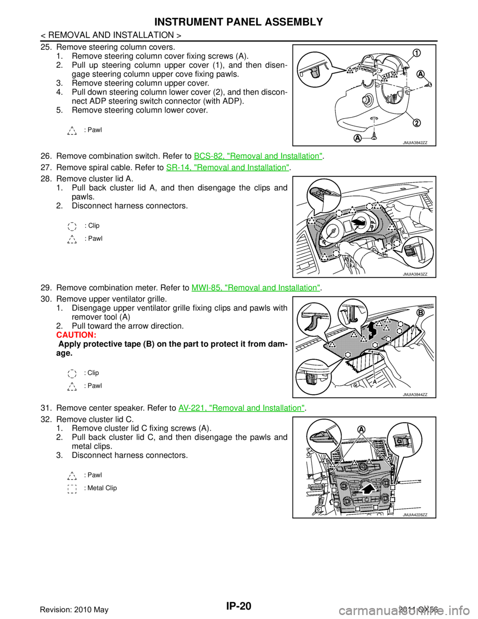
25. Remove steering column covers.1. Remove steering column cover fixing screws (A).
2. Pull up steering column upper cover (1), and then disen-gage steering column upper cove fixing pawls.
3. Remove steering column upper cover.
4. Pull down steering column lower cover (2), and then discon- nect ADP steering switch connector (with ADP).
5. Remove steering column lower cover.
26. Remove combination switch. Refer to BCS-82, "
Removal and Installation".
27. Remove spiral cable. Refer to SR-14, "
Removal and Installation".
28. Remove cluster lid A. 1. Pull back cluster lid A, and then disengage the clips and
pawls.
2. Disconnect harness connectors.
29. Remove combination meter. Refer to MWI-85, "
Removal and Installation".
30. Remove upper ventilator grille. 1. Disengage upper ventilator grille fixing clips and pawls with
remover tool (A)
2. Pull toward the arrow direction.
CAUTION:
Apply protective tape (B) on the part to protect it from dam-
age.
31. Remove center speaker. Refer to AV-221, "
Removal and Installation".
32. Remove cluster lid C. 1. Remove cluster lid C fixing screws (A).
2. Pull back cluster lid C, and then disengage the pawls and
metal clips.
3. Disconnect harness connectors.
: Pawl
JMJIA3842ZZ
: Clip
: Pawl
JMJIA3843ZZ
: Clip
: Pawl
JMJIA3844ZZ
: Pawl
: Metal Clip
JMJIA4228ZZ
Revision: 2010 May2011 QX56
Page 3414 of 5598
IP-24
< REMOVAL AND INSTALLATION >
CENTER CONSOLE ASSEMBLY
CONSOLE FINISHER ASSEMBLY
7. Second heated seat switch LH 8. 120W unit 9. Mask
10. Inner socket 11. Socket knob 12. Console ashtray
13. Mask (without ashtray) 14. Second heated seat switch RH 15. Console hinge cover
16. Console lid assembly 17. Console body assembly 18. Console box
19. Inside key antenna 20. Rear auxiliary input jacks 21. Console ashtray bracket
22. Console rear finisher 23. Rear A/C control: Clip
: Pawl
: Metal clip
JMJIA4230ZZ
1. AT control indicator assembly 2. 4WD: 4WD switch assembly 2WD: SNOW MODE/TOW MODE/
VDC OFF switch assembly3. Console pocket assembly
4. Cup holder assembly 5. Inner socket 6. Socket ring
7. Socket knob 8. USB connector 9. Inner case
10. Coin pocket : Clip
: Pawl
Revision: 2010 May2011 QX56
Page 3418 of 5598
IP-28
< REMOVAL AND INSTALLATION >
CENTER CONSOLE ASSEMBLY
4. Remove console power socket. Refer to PWO-11, "CONSOLE POWER SOCKET (REAR) : Removal and
Installation".
5. Remove 4WD switch assembly (2WD: SNOW MODE/TOW MODE/VDC OFF switch assembly). Refer to DLN-108, "
Removal and Installation".
ASSEMBLY
Assemble in the reverse order of disassembly.
Revision: 2010 May2011 QX56
Page 3450 of 5598
![INFINITI QX56 2011 Factory Service Manual
LAN-30
< SYSTEM DESCRIPTION >[CAN]
SYSTEM
P range signal T R R
R range signal T R R
Shift position signal R R T R R R R R
Tow mode indicator lamp
signalTR
Pre-roll over signal T R
Pre-tensioner oper INFINITI QX56 2011 Factory Service Manual
LAN-30
< SYSTEM DESCRIPTION >[CAN]
SYSTEM
P range signal T R R
R range signal T R R
Shift position signal R R T R R R R R
Tow mode indicator lamp
signalTR
Pre-roll over signal T R
Pre-tensioner oper](/manual-img/42/57033/w960_57033-3449.png)
LAN-30
< SYSTEM DESCRIPTION >[CAN]
SYSTEM
P range signal T R R
R range signal T R R
Shift position signal R R T R R R R R
Tow mode indicator lamp
signalTR
Pre-roll over signal T R
Pre-tensioner operation
signal TR
AFS OFF indicator lamp
signal TR
A/C switch operation signal T R
Rear window defogger
switch signal TR
System selection signal T R
System setting signal TR R
RT
RT
Automatic back door re-
quest signal TR
Back door lock status signal T R
Buzzer output signal TR
RT
Buzzer request signal TR
RT
Dimmer signal T R R
Door switch signal T R R R R
Door unlock signal T R
Front fog light request sig-
nal TR
Front wiper request signal T R R
Handle position signal T R
Headlamp washer request
signal TR
High beam request signal T R R
Horn reminder signal T R
Ignition switch ON signal TRRR
RT
Ignition switch signal T R
Interlock/PNP switch signal TR
RT
Key ID signal T R
Key switch signal T R
Key warning lamp signal T R
Low beam request signal T R Signal name
ECM
4WD
ABS
TCM
A-BAG
AFSAV
BCM
CGW
HVAC
M&A
STRG
TPMS
IPDM-E ADP
PSB
E-SUS ICC
PWBD
Revision: 2010 May2011 QX56