2011 INFINITI QX56 ignition
[x] Cancel search: ignitionPage 1496 of 5598

DEF-4
< PRECAUTION >
PRECAUTIONS
5. When the repair work is completed, re-connect both battery cables. With the brake pedal released, turn
the push-button ignition switch from ACC position to ON position, then to LOCK position. (The steering
wheel will lock when the push-button igniti on switch is turned to LOCK position.)
6. Perform self-diagnosis check of all control units using CONSULT-III.
Revision: 2010 May2011 QX56
Page 1498 of 5598
DEF-6
< SYSTEM DESCRIPTION >
SYSTEM
SYSTEM
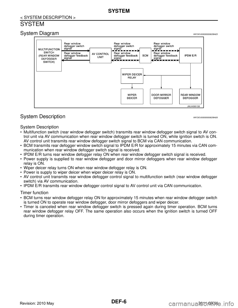
System DiagramINFOID:0000000006299425
System DescriptionINFOID:0000000006299426
System Description
Multifunction switch (rear window defogger switch) transmits rear window defogger switch signal to AV con-
trol unit via AV communication when rear window defogger switch is turned ON, while ignition switch is ON.
AV control unit transmits rear window defogger switch signal to BCM via CAN communication.
BCM transmits rear defogger window switch signal to IPDM E/R for approximately 15 minutes via CAN com-
munication when rear window defogger switch signal is received.
IPDM E/R turns rear window defogger relay ON when rear window defogger switch signal is received.
Power supply is supplied to rear window defogger and door mirror defoggers when rear window defogger
relay is ON.
Wiper deicer relay turns ON when rear window defogger relay is ON.
Power is supply to wiper deicer when wiper deicer relay is ON.
AV control unit transmits rear window defogger contro l signal to multifunction switch (rear window defogger
switch) via AV communication.
IPDM E/R transmits rear window defogger control signal to AV control unit via CAN communication.
Timer function
BCM turns rear window defogger relay ON for appr oximately 15 minutes when rear window defogger switch
is turned ON to operate rear window defogger, door mirror defoggers and wiper deicer.
Timer is canceled when rear window defogger switch is pressed again during timer operation. BCM turns
rear window defogger relay OFF. The same operation also occurs when the ignition switch is turned OFF
during timer operation.
JMLIA0981GB
Revision: 2010 May2011 QX56
Page 1500 of 5598

DEF-8
< SYSTEM DESCRIPTION >
DIAGNOSIS SYSTEM (BCM)
REAR WINDOW DEFOGGER
REAR WINDOW DEFOGGER : CONSULT-III Function (BCM - REAR DEFOGGER)
INFOID:0000000006299428
Data monitor
ACTIVE TEST
CONSULT screen item Indication/Unit Description
Vehicle Speed km/h Vehicle speed of the moment a particular DTC is detected
Odo/Trip Meter km Total mileage (Odometer value) of the moment a particular DTC is detected
Vehicle Condition SLEEP>LOCK
Power position status of
the moment a particular
DTC is detected While turning BCM status from low power consumption mode to
normal mode (Power supply position is “LOCK”)
SLEEP>OFF While turning BCM status from low power consumption mode to
normal mode (Power supply position is “OFF”.)
LOCK>ACC While turning power supply position from “LOCK” to “ACC”
ACC>ON While turning power supply position from “ACC” to “IGN”
RUN>ACC While turning power supp
ly position from “RUN” to “ACC” (Vehicle
is stopping and selector lever is except P position.)
CRANK>RUN While turning power su
pply position from “CRANKING” to “RUN”
(From cranking up the engine to run it)
RUN>URGENT While turning power supply positi
on from “RUN“ to “ACC” (Emer-
gency stop operation)
ACC>OFF While turning power supply position from “ACC” to “OFF”
OFF>LOCK While turning power supply position from “OFF” to “LOCK”
OFF>ACC While turning power supply position from “OFF” to “ACC”
ON>CRANK While turning power supply position from “IGN” to “CRANKING”
OFF>SLEEP While turning BCM status from normal mode (Power supply posi-
tion is “OFF”.) to low power consumption mode
LOCK>SLEEP While turning BCM status from normal mode (Power supply posi-
tion is “LOCK”.) to low power consumption mode
LOCK Power supply position is “LOCK”
(Ignition switch OFF with steer-
ing is locked.)
OFF Power supply position is “OFF” (Ignition switch OFF with steering
is unlocked.)
ACC Power supply position is “ACC” (Ignition switch ACC)
ON Power supply position is “IGN” (Ignition switch ON with engine
stopped)
ENGINE RUN Power supply position is “RUN” (Ignition switch ON with engine
running)
CRANKING Power supply position is “CRANKING” (At engine cranking)
IGN Counter 0 - 39 The number of times that ignition switch is turned ON after DTC is detected
The number is 0 when a malfunction is detected now.
The number increases like 1
→ 2 → 3...38 → 39 after returning to the normal condition
whenever ignition switch OFF → ON.
The number is fixed to 39 until the self-diagnosis results are erased if it is over 39.
Monitor Item Description
REAR DEF SW Displays “Press (ON)/other (OFF)” status determined with the rear window defogger switch.
PUSH SW Indicates [ON/OFF] condition of push switch.
Revision: 2010 May2011 QX56
Page 1502 of 5598
DEF-10
< SYSTEM DESCRIPTION >
DIAGNOSIS SYSTEM (IPDM E/R)
DIAGNOSIS SYSTEM (IPDM E/R)
Diagnosis DescriptionINFOID:0000000006349776
AUTO ACTIVE TEST
Description
In auto active test, the IPDM E/R sends a drive signal to the following systems to check their operation.
Oil pressure warning lamp
Rear window defogger
Front wiper (LO, HI)
Parking lamp
License plate lamp
Tail lamp
Side marker lamp
Front fog lamp
Headlamp (LO, HI)
A/C compressor (magnet clutch)
Operation Procedure
CAUTION:
Never perform auto active test in the following conditions.
Engine is running.
CONSULT-III is connected.
1. Close the hood and lift the wiper arms from the windshield. (Prevent windshield damage due to wiper
operation)
NOTE:
When auto active test is performed with hood opened, sprinkle water on windshield beforehand.
2. Turn the ignition switch OFF.
3. Turn the ignition switch ON, and within 20 seconds, pr ess the driver door switch 10 times. Then turn the
ignition switch OFF.
CAUTION:
Close passenger door.
4. Turn the ignition switch ON within 10 seconds. Af ter that the horn sounds once and the auto active test
starts.
CAUTION:
Engine starts when igniti on switch is turned ON while brake pedal is depressed.
5. The oil pressure warning lamp starts blinking when the auto active test starts.
6. After a series of the following operations is repeated 3 times, auto active test is completed.
NOTE:
When auto active test has to be cancelled halfway through test, turn the ignition switch OFF.
When auto active test is not activated, door swit ch may be the cause. Check door switch. Refer to DLK-117,
"ComponentFunctionCheck".
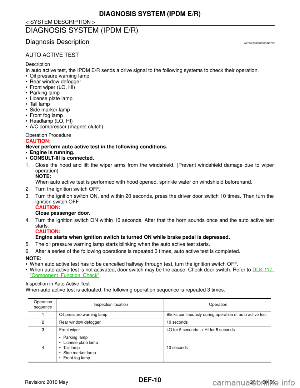
Inspection in Auto Active Test
When auto active test is actuated, the following operation sequence is repeated 3 times.
Operation
sequence Inspection location Operation
1 Oil pressure warning lamp Blinks continuously during operation of auto active test
2 Rear window defogger 10 seconds
3 Front wiper LO for 5 seconds → HI for 5 seconds
4 Parking lamp
License plate lamp
Tail lamp
Side marker lamp
Front fog lamp 10 seconds
Revision: 2010 May2011 QX56
Page 1504 of 5598
DEF-12
< SYSTEM DESCRIPTION >
DIAGNOSIS SYSTEM (IPDM E/R)
CONSULT-III Function (IPDM E/R)
INFOID:0000000006349777
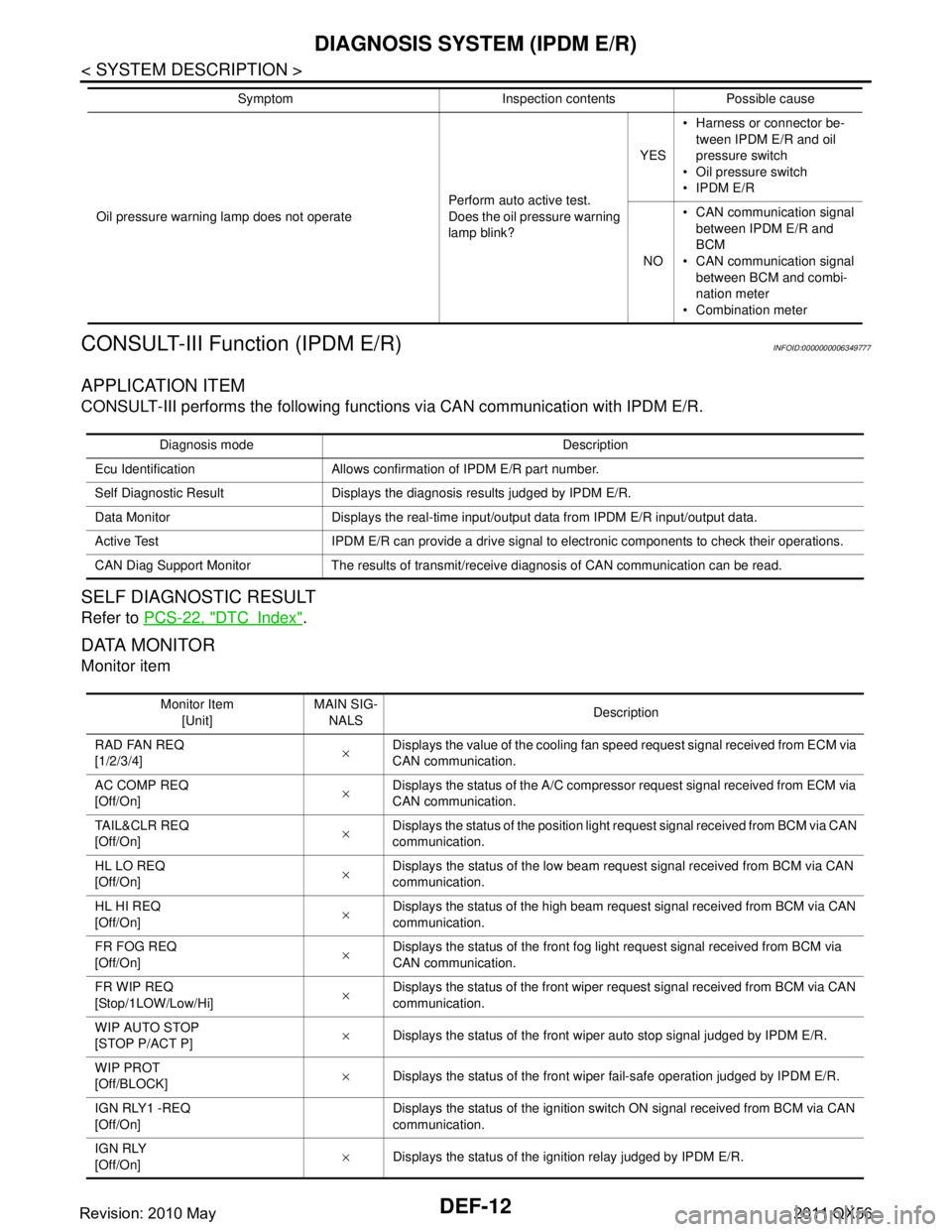
APPLICATION ITEM
CONSULT-III performs the following functions via CAN communication with IPDM E/R.
SELF DIAGNOSTIC RESULT
Refer to PCS-22, "DTCIndex".
DATA MONITOR
Monitor item
Oil pressure warning lamp does not operate Perform auto active test.
Does the oil pressure warning
lamp blink?YES
Harness or connector be-
tween IPDM E/R and oil
pressure switch
Oil pressure switch
IPDM E/R
NO CAN communication signal
between IPDM E/R and
BCM
CAN communication signal
between BCM and combi-
nation meter
Combination meter
Symptom Inspection contents Possible cause
Diagnosis mode Description
Ecu Identification Allows confirmation of IPDM E/R part number.
Self Diagnostic Result Displays the diagnosis results judged by IPDM E/R.
Data Monitor Displays the real-time input/output data from IPDM E/R input/output data.
Active Test IPDM E/R can provide a drive signal to electronic components to check their operations.
CAN Diag Support Monitor The results of transmit/receive diagnosis of CAN communication can be read.
Monitor Item [Unit] MAIN SIG-
NALS Description
RAD FAN REQ
[1/2/3/4] ×Displays the value of the cooling fan speed request signal received from ECM via
CAN communication.
AC COMP REQ
[Off/On] ×Displays the status of the A/C compressor request signal received from ECM via
CAN communication.
TA I L & C L R R E Q
[Off/On] ×
Displays the status of the position light request signal received from BCM via CAN
communication.
HL LO REQ
[Off/On] ×Displays the status of the low beam request signal received from BCM via CAN
communication.
HL HI REQ
[Off/On] ×Displays the status of the high beam request signal received from BCM via CAN
communication.
FR FOG REQ
[Off/On] ×Displays the status of the front fog light request signal received from BCM via
CAN communication.
FR WIP REQ
[Stop/1LOW/Low/Hi] ×
Displays the status of the front wiper request signal received from BCM via CAN
communication.
WIP AUTO STOP
[STOP P/ACT P] ×
Displays the status of the front wiper auto stop signal judged by IPDM E/R.
WIP PROT
[Off/BLOCK] ×
Displays the status of the front wiper fail-safe operation judged by IPDM E/R.
IGN RLY1 -REQ
[Off/On] Displays the status of the ignition switch ON signal received from BCM via CAN
communication.
IGN RLY
[Off/On] ×
Displays the status of the ignition relay judged by IPDM E/R.
Revision: 2010 May2011 QX56
Page 1505 of 5598
![INFINITI QX56 2011 Factory Service Manual
DIAGNOSIS SYSTEM (IPDM E/R)DEF-13
< SYSTEM DESCRIPTION >
C
DE
F
G H
I
J
K
M A
B
DEF
N
O P
ACTIVE TEST
Te s t i t e m
PUSH SW
[Off/On] Displays the status of the push-button ignition switch judged by INFINITI QX56 2011 Factory Service Manual
DIAGNOSIS SYSTEM (IPDM E/R)DEF-13
< SYSTEM DESCRIPTION >
C
DE
F
G H
I
J
K
M A
B
DEF
N
O P
ACTIVE TEST
Te s t i t e m
PUSH SW
[Off/On] Displays the status of the push-button ignition switch judged by](/manual-img/42/57033/w960_57033-1504.png)
DIAGNOSIS SYSTEM (IPDM E/R)DEF-13
< SYSTEM DESCRIPTION >
C
DE
F
G H
I
J
K
M A
B
DEF
N
O P
ACTIVE TEST
Te s t i t e m
PUSH SW
[Off/On] Displays the status of the push-button ignition switch judged by IPDM E/R.
INTER/NP SW
[Off/On] Displays the status of the shift position judged by IPDM E/R.
ST RLY CONT
[Off/On] Displays the status of the starter relay status signal received from BCM via CAN
communication.
IHBT RLY -REQ
[Off/On] Displays the status of the starter control relay signal received from BCM via CAN
communication.
ST/INHI RLY
[Off/ ST ON/INHI ON/UNKWN] Displays the status of the starter relay and starter control relay judged by IPDM
E/R.
DETENT SW
[Off/On] Displays the status of the A/T shift selector (detention switch) judged by IPDM E/
R.
S/L RLY -REQ
[Off/On] Displays the status of the steering lock relay signal received from BCM via CAN
communication.
S/L STATE
[LOCK/UNLK/UNKWN] Displays the status of the steering lock judged by IPDM E/R.
OIL P SW
[Open/Close] Displays the status of the oil pressure switch judged by IPDM E/R.
HOOD SW
[Off/On] Displays the status of the hood switch judged by IPDM E/R.
HL WASHER REQ
[Off/On] Displays the status of the headlamp washer request signal received from BCM via
CAN communication.
THFT HRN REQ
[Off/On] Displays the status of the theft warning horn request signal received from BCM
via CAN communication.
HORN CHIRP
[Off/On] Displays the status of the horn reminder signal received from BCM via CAN com-
munication.
Monitor Item
[Unit] MAIN SIG-
NALS Description
Test item Operation Description
CORNERING LAMP LH
NOTE:
This item is indicated, but cannot be tested.
RH
HORN On Operates horn relay for 20 ms.
REAR DEFOGGER Off OFF
On Operates the rear window defogger relay.
FRONT WIPER Off OFF
Lo Operates the front wiper relay.
Hi Operates the front wiper relay and front wiper high relay.
MOTOR FAN* 1OFF
2 Transmits 50% pulse duty signal (PWM signal) to the cooling fan control module.
3 Transmits 75% pulse duty signal (PWM signal) to the cooling fan control module.
4
Transmits 100% pulse duty signal (PWM signal) to the cooling fan control mod-
ule.
HEAD LAMP WASHER On Operates the headlamp washer relay for 1 second.
Revision: 2010 May2011 QX56
Page 1518 of 5598
DEF-26
< DTC/CIRCUIT DIAGNOSIS >
REAR WINDOW DEFOGGER RELAY
REAR WINDOW DEFOGGER RELAY
DescriptionINFOID:0000000006299436
The rear window defogger is operated by turning the rear window defogger switch ON.
Component Function CheckINFOID:0000000006299437
1.CHECK FUNCTION
1. Perform IPDM E/R Active Test (“REAR DEFOGGER”) using CONSULT-III.
2. Touch “ON”.
3. Check that the rear window heating wire is getting warmer.
Is the inspection result normal?
YES >> Rear window defogger relay function is OK.
NO >> Refer to DEF-26, "
Diagnosis Procedure"
Diagnosis ProcedureINFOID:0000000006299438
1.CHECK FUSE
1. Turn ignition switch OFF.
2. Check the 15A fuse (No. 41, 42 located in IPDM E/R).
Is the inspection result normal?
YES >> GO TO 2.
NO >> Replace the blown fuse after repairing the affected circuit if a fuse is blown.
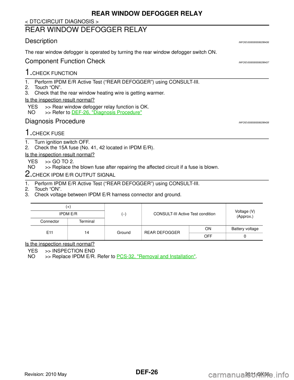
2.CHECK IPDM E/R OUTPUT SIGNAL
1. Perform IPDM E/R Active Test (“REAR DEFOGGER”) using CONSULT-III.
2. Touch “ON”.
3. Check voltage between IPDM E/R harness connector and ground.
Is the inspection result normal?
YES >> INSPECTION END
NO >> Replace IPDM E/R. Refer to PCS-32, "
Removal and Installation".
(+)
(− ) CONSULT-III Active Test condition Voltage (V)
(Approx.)
IPDM E/R
Connector Terminal
E11 14 Ground REAR DEFOGGER ON Battery voltage
OFF 0
Revision: 2010 May2011 QX56
Page 1519 of 5598
REAR WINDOW DEFOGGERDEF-27
< DTC/CIRCUIT DIAGNOSIS >
C
DE
F
G H
I
J
K
M A
B
DEF
N
O P
REAR WINDOW DEFOGGER
DescriptionINFOID:0000000006299439
Heats the heating wire with the power supply from the rear window defogger relay to prevent the rear window
from fogging up.
Component Function CheckINFOID:0000000006299440
1.CHECK FUNCTION
1. Perform IPDM E/R Active Test (“REAR DEFOGGER”) using CONSULT-III.
2. Touch “ON”.
3. Check that the rear window heating wire is getting warmer.
Is the inspection result normal?
YES >> Rear window defogger relay function is OK.
NO >> Refer to DEF-26, "
Diagnosis Procedure"
Diagnosis ProcedureINFOID:0000000006299441
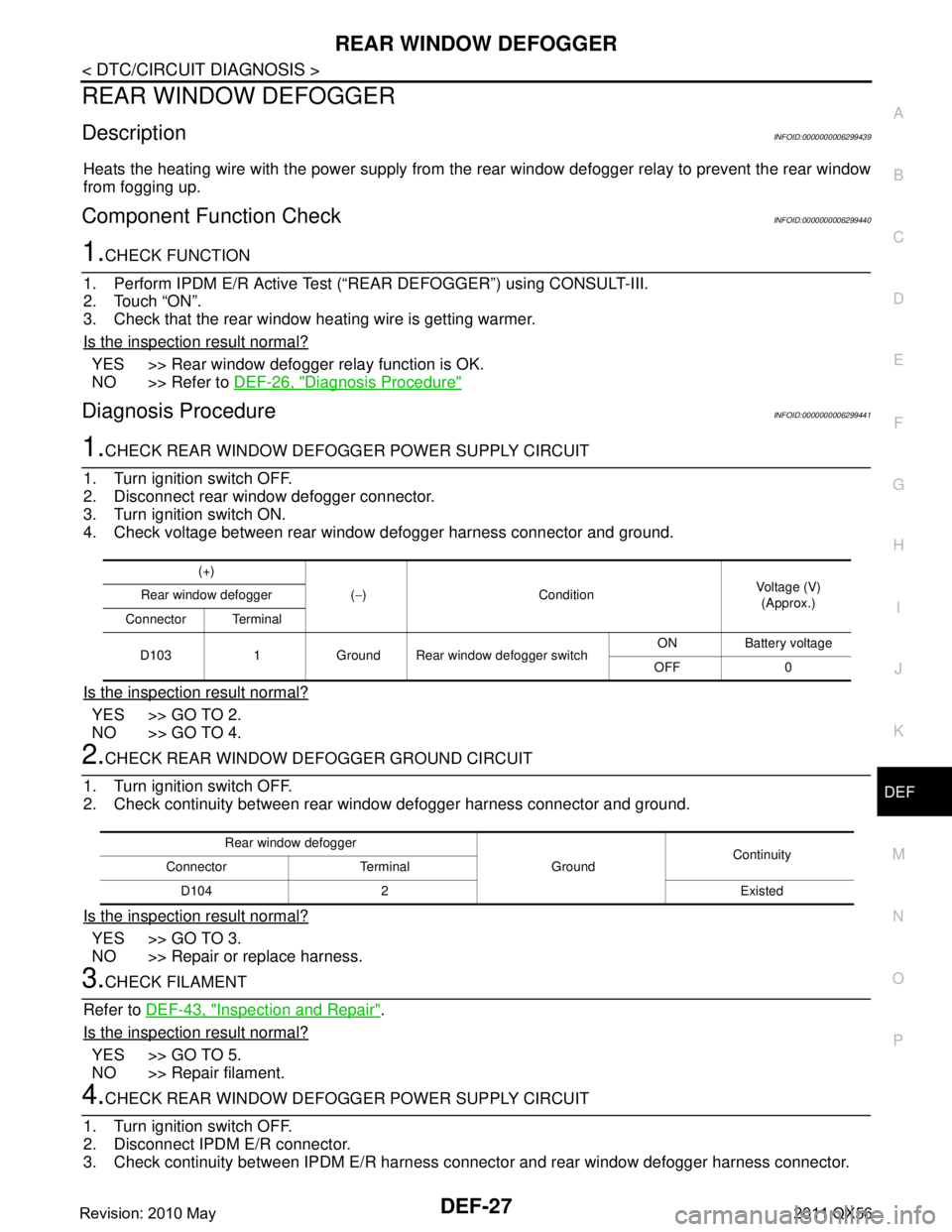
1.CHECK REAR WINDOW DEFOGG ER POWER SUPPLY CIRCUIT
1. Turn ignition switch OFF.
2. Disconnect rear window defogger connector.
3. Turn ignition switch ON.
4. Check voltage between rear window defogger harness connector and ground.
Is the inspection result normal?
YES >> GO TO 2.
NO >> GO TO 4.
2.CHECK REAR WINDOW DE FOGGER GROUND CIRCUIT
1. Turn ignition switch OFF.
2. Check continuity between rear window defogger harness connector and ground.
Is the inspection result normal?
YES >> GO TO 3.
NO >> Repair or replace harness.
3.CHECK FILAMENT
Refer to DEF-43, "
Inspection and Repair".
Is the inspection result normal?
YES >> GO TO 5.
NO >> Repair filament.
4.CHECK REAR WINDOW DEFOGG ER POWER SUPPLY CIRCUIT
1. Turn ignition switch OFF.
2. Disconnect IPDM E/R connector.
3. Check continuity between IPDM E/R harness connector and rear window defogger harness connector.
(+)
(− ) Condition Voltage (V)
(Approx.)
Rear window defogger
Connector Terminal
D103 1 Ground Rear window defogger switch ON Battery voltage
OFF 0
Rear window defogger GroundContinuity
Connector Terminal
D104 2 Existed
Revision: 2010 May2011 QX56