2011 INFINITI QX56 ignition
[x] Cancel search: ignitionPage 1521 of 5598

DOOR MIRROR DEFOGGERDEF-29
< DTC/CIRCUIT DIAGNOSIS >
C
DE
F
G H
I
J
K
M A
B
DEF
N
O P
DOOR MIRROR DEFOGGER
DescriptionINFOID:0000000006299442
Heats the heating wire with the power supply from t he rear window defogger relay to prevent the door mirror
from fogging up.
Component Function CheckINFOID:0000000006299443
1.CHECK DOOR MIRROR DEFOGGER
1. Perform IPDM E/R Active Test (“REAR DEFOGGER”) using CONSULT-III.
2. Touch “ON”.
3. Check that both side door mirror glasses are getting warmer.
Is the inspection result normal?
YES >> Door mirror defogger is OK.
NO >> Refer to DEF-29, "
Diagnosis Procedure"
Diagnosis ProcedureINFOID:0000000006299444
1.CHECK FUSE
1. Turn ignition switch OFF.
2. Check 10A fuse [No.80, loca ted in fuse block (J/B)].
Is the inspection result normal?
YES >> GO TO 2.
NO >> Replace the blown fuse after repairing the affected circuit if a fuse is blown.
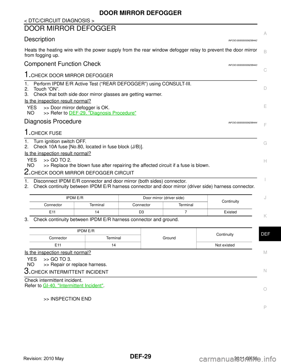
2.CHECK DOOR MIRROR DEFOGGER CIRCUIT
1. Disconnect IPDM E/R connector and door mirror (both sides) connector.
2. Check continuity between IPDM E/R harness connec tor and door mirror (driver side) harness connector.
3. Check continuity between IPDM E/R harness connector and ground.
Is the inspection result normal?
YES >> GO TO 3.
NO >> Repair or replace harness.
3.CHECK INTERMITTENT INCIDENT
Check intermittent incident.
Refer to GI-40, "
Intermittent Incident".
>> INSPECTION END
IPDM E/R Door mirro r (driver side)
Continuity
Connector Terminal Connector Terminal
E11 14 D3 7 Existed
IPDM E/R GroundContinuity
Connector Terminal
E11 14 Not existed
Revision: 2010 May2011 QX56
Page 1522 of 5598

DEF-30
< DTC/CIRCUIT DIAGNOSIS >
DRIVER SIDE DOOR MIRROR DEFOGGER
DRIVER SIDE DOOR MIRROR DEFOGGER
DescriptionINFOID:0000000006299445
Heats the heating wire with the power supply from the rear window defogger relay to prevent the door mirror
from fogging up.
Component Function CheckINFOID:0000000006299446
1.CHECK DRIVER SIDE DOOR MIRROR DEFOGGER
1. Perform IPDM E/R Active Test (“REAR DEFOGGER”) using CONSULT-III.
2. Touch “ON”.
3. Check that the driver side door mirror glass is getting warmer.
Is the inspection result normal?
YES >> Driver side door mirror defogger is OK.
NO >> Refer to DEF-30, "
Diagnosis Procedure"
Diagnosis ProcedureINFOID:0000000006299447
1.CHECK POWER SUPPLY CIRCUIT
1. Turn ignition switch OFF.
2. Disconnect door mirror (driver side) connector.
3. Turn ignition switch ON.
4. Check voltage between door mirror (driver side) harness connector and ground.
Is the inspection result normal?
YES >> GO TO 2.
NO >> Repair or replace harness.
2.CHECK GROUND CIRCUIT
1. Turn ignition switch OFF.
2. Check continuity between door mirror (driver side) harness connector and ground.
Is the inspection result normal?
YES >> Replace door mirror glass (driver side).
NO >> Repair or replace harness.
(+)
(–) Condition Voltage (V)
(Approx.)
Door mirror (driver side)
Connector Terminal
D3 7 Ground Rear window defogger
switchON Battery voltage
OFF 0
Door mirror (driver side)
GroundContinuity
Connector Terminal
D3 19 Existed
Revision: 2010 May2011 QX56
Page 1523 of 5598

PASSENGER SIDE DOOR MIRROR DEFOGGERDEF-31
< DTC/CIRCUIT DIAGNOSIS >
C
DE
F
G H
I
J
K
M A
B
DEF
N
O P
PASSENGER SIDE DOOR MIRROR DEFOGGER
DescriptionINFOID:0000000006299448
Heats the heating wire with the power supply from t he rear window defogger relay to prevent the door mirror
from fogging up.
Component Function CheckINFOID:0000000006299449
1.CHECK PASSENGER SIDE DOOR MIRROR DEFOGGER
1. Perform IPDM E/R Active Test (“REAR DEFOGGER”) using CONSULT-III.
2. Touch “ON”.
3. Check that the passenger side door mirror glass is getting warmer.
Is the inspection result normal?
YES >> Passenger side door mirror defogger is OK.
NO >> Refer to DEF-31, "
Diagnosis Procedure"
Diagnosis ProcedureINFOID:0000000006299450
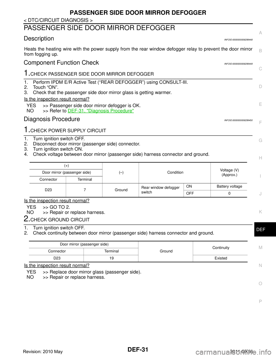
1.CHECK POWER SUPPLY CIRCUIT
1. Turn ignition switch OFF.
2. Disconnect door mirror (passenger side) connector.
3. Turn ignition switch ON.
4. Check voltage between door mirror (passenger side) harness connector and ground.
Is the inspection result normal?
YES >> GO TO 2.
NO >> Repair or replace harness.
2.CHECK GROUND CIRCUIT
1. Turn ignition switch OFF.
2. Check continuity between door mirror (passenger side) harness connector and ground.
Is the inspection result normal?
YES >> Replace door mirror glass (passenger side).
NO >> Repair or replace harness.
(+)
(–) Condition Voltage (V)
(Approx.)
Door mirror (passenger side)
Connector Terminal
D23 7 Ground Rear window defogger
switchON Battery voltage
OFF 0
Door mirror (passenger side)
GroundContinuity
Connector Terminal
D23 19 Existed
Revision: 2010 May2011 QX56
Page 1524 of 5598

DEF-32
< DTC/CIRCUIT DIAGNOSIS >
WIPER DEICER RELAY
WIPER DEICER RELAY
Component Function CheckINFOID:0000000006299451
1.CHECK WIPER DEICER RELAY POWER SUPPLY CIRCUIT
1. Select Active Test (“REAR DEFOGGER”) mode of “BCM” using CONSULT-III.
2. Touch “ON”.
3. Check that the front window heating wire is getting warmer.
Is the inspection result normal?
YES >> Wiper deicer relay power supply circuit function is OK.
NO >> Refer to DEF-32, "
Diagnosis Procedure".
Diagnosis ProcedureINFOID:0000000006299452
1.CHECK WIPER DEICER CIRCUIT 1
1. Turn ignition switch ON.
2. Check voltage between wiper deicer relay harness connector and ground.
Is the inspection result normal?
YES >> GO TO 3.
NO >> GO TO 2.
2.CHECK WIPER DEICER CIRCUIT 2
1. Turn ignition switch OFF.
2. Disconnect wiper deicer relay and IPDM E/R connector.
3. Check continuity between wiper deicer relay terminal connector and IPDM E/R harness connector.
Is the inspection result normal?
YES >> GO TO 6.
NO >> Repair or replace harness.
3.CHECK WIPER DEICER CIRCUIT 3
Check voltage between wiper deicer relay harness connector and ground.
Is the inspection result normal?
YES >> GO TO 4.
NO >> Repair or replace harness.
4.CHECK WIPER DEICER RELAY GROUND CIRCUIT
1. Turn ignition switch OFF.
2. Disconnect wiper deicer relay connector.
3. Check continuity between wiper deicer relay terminal connector and ground.
(+)
(–) Condition Voltage (V)
(Approx.)
Wiper deicer relay
Connector Terminal
E23 1 Ground Rear window defogger switch: ON Battery voltage
Rear window defogger switch: OFF 0
Wiper deicer relay IPDM E/R
Continuity
Connector Terminal Connector Terminal
E23 1 E11 14 Existed
(+) (–)Voltage (V)
(Approx.)
Wiper deicer relay
Connector Terminal E23 3 Ground Battery voltage
Revision: 2010 May2011 QX56
Page 1525 of 5598

WIPER DEICER RELAYDEF-33
< DTC/CIRCUIT DIAGNOSIS >
C
DE
F
G H
I
J
K
M A
B
DEF
N
O P
Is the inspection result normal?
YES >> GO TO 5.
NO >> Repair or replace harness.
5.CHECK WIPER DEICER RELAY
Check wiper deicer relay.
Refer to DEF-33, "
Component Inspection".
Is the inspection result normal?
YES >> GO TO 6.
NO >> Replace wiper deicer relay.
6.CHECK INTERMITTENT INCIDENT
Check intermittent incident.
Refer to GI-40, "
Intermittent Incident".
>> INSPECTION END
Component InspectionINFOID:0000000006299453
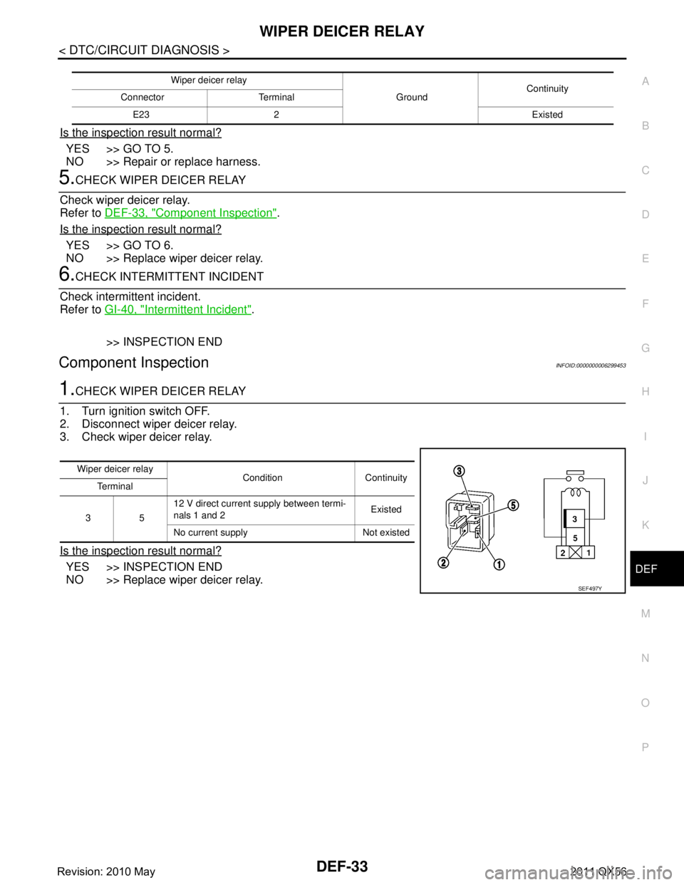
1.CHECK WIPER DEICER RELAY
1. Turn ignition switch OFF.
2. Disconnect wiper deicer relay.
3. Check wiper deicer relay.
Is the inspection result normal?
YES >> INSPECTION END
NO >> Replace wiper deicer relay.
Wiper deicer relay
GroundContinuity
Connector Terminal
E23 2 Existed
Wiper deicer relay Condition Continuity
Te r m i n a l
35 12 V direct current supply between termi-
nals 1 and 2
Existed
No current supply Not existed
SEF497Y
Revision: 2010 May2011 QX56
Page 1526 of 5598

DEF-34
< DTC/CIRCUIT DIAGNOSIS >
WIPER DEICER
WIPER DEICER
Component Function CheckINFOID:0000000006299454
1.CHECK WIPER DEICER
1. Select Active Test (“REAR DEFOGGER”) mode of “BCM” using CONSULT-III.
2. Touch “ON”.
3. Check that the front window heating wire is getting warmer.
Is the inspection result normal?
YES >> Wiper deicer is OK.
NO >> Refer to DEF-34, "
Diagnosis Procedure"
Diagnosis ProcedureINFOID:0000000006299455
1.CHECK FUSE
1. Turn ignition switch OFF.
2. Check 15 A fuse [No.75, located in fuse block (J/B)]
Is the inspection result normal?
YES >> GO TO 2.
NO >> Replace the blown fuse after repairing the affected circuit if a fuse is blown.
2.CHECK POWER SUPPLY CIRCUIT
1. Turn ignition switch ON.
2. Check voltage between wiper deicer harness connector and ground.
Is the inspection result normal?
YES >> GO TO 3.
NO >> GO TO 4.
3.CHECK GROUND CIRCUIT
1. Turn ignition switch OFF.
2. Disconnect wiper deicer connector.
3. Check continuity between wiper deicer harness connector and ground.
Is the inspection result normal?
YES >> GO TO 5.
NO >> Repair or replace harness between rear window defogger and ground.
4.CHECK WIPER DEICER CIRCUIT
1. Turn ignition switch OFF.
2. Disconnect wiper deicer relay connector and wiper deicer connector.
3. Check continuity between wiper deicer relay harness connector and wiper deicer harness connector.
(+)
(–) Condition Voltage (V)
(Approx.)
Wiper deicer
Connector Terminal
E40 1 Ground Rear window defogger switch: ON Battery voltage
Rear window defogger switch: OFF 0
Wiper deicer
GroundContinuity
Connector Terminal
E40 2 Existed
Revision: 2010 May2011 QX56
Page 1538 of 5598

DLK-2
DOOR LOCK .............................................................39
DOOR LOCK : CONSULT-III Function (BCM -
DOOR LOCK) .........................................................
39
INTELLIGENT KEY ................................................ ...40
INTELLIGENT KEY : CONSULT-III Function
(BCM - INTELLIGENT KEY) ...................................
41
TRUNK ................................................................... ...44
TRUNK : CONSULT-III Function (BCM - TRUNK) ...44
DIAGNOSIS SYSTEM (AUTOMATIC BACK
DOOR CONTROL UNIT) ...................................
45
CONSULT-III Function (AUTOMATIC BACK
DOOR CONTROL UNIT) ..................................... ...
45
ECU DIAGNOSIS INFORMATION ..............46
BCM ................................................................ ...46
List of ECU Reference ......................................... ...46
AUTOMATIC BACK DOOR CONTROL MOD-
ULE ....................................................................
47
Reference Value .................................................. ...47
Fail Safe .................................................................49
DTC Inspection Priority Chart ..............................49
DTC Index ..............................................................50
WIRING DIAGRAM .....................................51
DOOR & LOCK SYSTEM ............................... ...51
Wiring Diagram - DOOR & LOCK SYSTEM - ...... ...51
AUTOMATIC BACK DOOR SYSTEM ...............66
Wiring Diagram - AUTOMATIC BACK DOOR
SYSTEM - ............................................ ...................
66
INTEGRATED HOMELINK TRANSMITTER
SYSTEM ............ .............................................. ...
75
Wiring Diagram - INTEGRATED HOMELINK
TRANSMITTER SYSTEM - ....................................
75
BASIC INSPECTION ...... .............................77
DIAGNOSIS AND REPAIR WORK FLOW ..... ...77
Work Flow ............................................................ ...77
INSPECTION AND ADJUSTMENT ...................80
ADDITIONAL SERVICE WHEN REMOVING BAT-
TERY NEGATIVE TERMINAL ............................... ...
80
ADDITIONAL SERVICE WHEN REMOVING
BATTERY NEGATIVE TERMINAL : Description ....
80
ADDITIONAL SERVICE WHEN REMOVING
BATTERY NEGATIVE TERMINAL : Work Proce-
dure ........................................................................
80
ADDITIONAL SERVICE WHEN REPLACING
CONTROL UNIT (BCM) ......................................... ...
80
ADDITIONAL SERVICE WHEN REPLACING
CONTROL UNIT (BCM) : Description ....................
80
ADDITIONAL SERVICE WHEN REPLACING
CONTROL UNIT (BCM) : Work Procedure .......... ...
80
ADDITIONAL SERVICE WHEN REPLACING (AU-
TOMATIC BACK DOOR CONTROL MODULE) .......
80
ADDITIONAL SERVICE WHEN REPLACING
(AUTOMATIC BACK DOOR CONTROL MOD-
ULE) : Description ................................................ ...
80
ADDITIONAL SERVICE WHEN REPLACING
(AUTOMATIC BACK DOOR CONTROL MOD-
ULE) : Work Procedure ........................................ ...
80
DTC/CIRCUIT DIAGNOSIS ........................82
U1000 CAN COMM CIRCUIT ......................... ...82
Description ........................................................... ...82
DTC Logic ...............................................................82
Diagnosis Procedure ...............................................82
U1010 CONTROL UNIT (CAN) .........................83
DTC Logic ............................................................ ...83
Diagnosis Procedure ...............................................83
B2401 IGNITION POWER SUPPLY CIRCUIT ...84
DTC Logic ............................................................ ...84
Diagnosis Procedure ...............................................84
B2403 ENCODER ..............................................85
DTC Logic ............................................................ ...85
Diagnosis Procedure ...............................................85
B2409 HALF LATCH SWITCH ..........................86
DTC Logic ............................................................ ...86
Diagnosis Procedure ...............................................86
Component Inspection ............................................87
B2416 TOUCH SENSOR RH ............................88
DTC Logic ............................................................ ...88
Diagnosis Procedure ...............................................88
Component Inspection ............................................89
B2417 TOUCH SENSOR LH .............................90
DTC Logic ............................................................ ...90
Diagnosis Procedure ...............................................90
Component Inspection ............................................91
B2419 OPEN SWITCH ......................................92
DTC Logic ............................................................ ...92
Diagnosis Procedure ...............................................92
Component Inspection ............................................93
B2420 CLOSE SWITCH ....................................95
DTC Logic ............................................................ ...95
Diagnosis Procedure ...............................................95
Component Inspection ............................................96
B2421 CLUTCH OPERATION TIME .................97
DTC Logic ............................................................ ...97
Diagnosis Procedure ...............................................97
B2422 BACK DOOR STATE .............................98
DTC Logic ............................................................ ...98
Revision: 2010 May2011 QX56
Page 1541 of 5598

DLK-5
C
DE
F
G H
I
J
L
M A
B
DLK
N
O P
FUEL LID LOCK ACTUATOR DOES NOT OP-
ERATE ............................................................ ..
176
Diagnosis Procedure ........................................... ..176
IGNITION POSITION WARNING FUNCTION
DOES NOT OPERATE .....................................
177
Diagnosis Procedure ........................................... ..177
SELECTIVE UNLOCK FUNCTION DOES
NOT OPERATE ................................................
178
Diagnosis Procedure ........................................... ..178
AUTO DOOR LOCK OPERATION DOES NOT
OPERATE .........................................................
179
Diagnosis Procedure ........................................... ..179
VEHICLE SPEED SENSING AUTO LOCK
OPERATION DOES NOT OPERATE ..............
180
Diagnosis Procedure ........................................... ..180
IGN OFF INTERLOCK DOOR UNLOCK
FUNCTION DOES NOT OPERATE .................
181
Diagnosis Procedure ........................................... ..181
P RANGE INTERLOCK DOOR LOCK/UN-
LOCK FUNCTION DOES NOT OPERATE ......
182
Diagnosis Procedure ........................................... ..182
HAZARD AND HORN REMINDER DOES
NOT OPERATE ................................................
183
Diagnosis Procedure ........................................... ..183
HAZARD AND BUZZER REMINDER DOES
NOT OPERATE ................................................
184
Diagnosis Procedure ........................................... ..184
KEY REMINDER FUNCTION DOES NOT OP-
ERATE ..............................................................
185
Diagnosis Procedure ........................................... ..185
WELCOME LIGHT FUNCTION DOES NOT
OPERATE .........................................................
186
Diagnosis Procedure ........................................... ..186
OFF POSITION WARNING DOES NOT OP-
ERATE ..............................................................
188
Diagnosis Procedure ........................................... ..188
P POSITION WARNING DOES NOT OPER-
ATE ...................................................................
189
Description .......................................................... ..189
Diagnosis Procedure .............................................189
ACC WARNING DOES NOT OPERATE .........191
Description .......................................................... ..191
Diagnosis Procedure .............................................191
TAKE AWAY WARNING DOES NOT OPER-
ATE ...................................................................
192
Description .......................................................... ..192
Diagnosis Procedure .............................................192
KEY ID WARNING DOES NOT OPERATE ....194
Description ........................................................... ..194
Diagnosis Procedure .............................................194
INTELLIGENT KEY LOW BATTERY WARN-
ING DOES NOT OPERATE ............................
195
Description .............................................................195
Diagnosis Procedure .............................................195
DOOR LOCK OPERATION WARNING DOES
NOT OPERATE ...............................................
197
Diagnosis Procedure .............................................197
AUTOMATIC BACK DOOR OPERATION
DOES NOT OPERATE ....................................
198
ALL SWITCHES ..................................................... ..198
ALL SWITCHES : Description ...............................198
ALL SWITCHES : Diagnosis Procedure ................198
AUTOMATIC BACK DOOR SWITCH .................... ..199
AUTOMATIC BACK DOOR SWITCH : Descrip-
tion .........................................................................
199
AUTOMATIC BACK DOOR SWITCH : Diagnosis
Procedure ..............................................................
199
AUTOMATIC BACK DOOR CLOSE SWITCH ........199
AUTOMATIC BACK DOOR CLOSE SWITCH :
Description ........................................................... ..
199
AUTOMATIC BACK DOOR CLOSE SWITCH : Di-
agnosis Procedure .................................................
199
INTELLIGENT KEY ................................................ ..200
INTELLIGENT KEY : Description ..........................200
INTELLIGENT KEY : Diagnosis Procedure ......... ..200
BACK DOOR OPENER SWITCH .......................... ..200
BACK DOOR OPENER SWITCH : Description .....200
BACK DOOR OPENER SWITCH : Diagnosis Pro-
cedure ....................................................................
200
OPEN/CLOSURE FUNCTION ............................... ..201
OPEN/CLOSURE FUNCTION : Description .........201
OPEN/CLOSURE FUNCTION : Diagnosis Proce-
dure .......................................................................
201
OPEN FUNCTION .................................................. ..202
OPEN FUNCTION : Description ............................202
OPEN FUNCTION : Diagnosis Procedure ............202
CLOSURE FUNCTION .......................................... ..202
CLOSURE FUNCTION : Description .....................202
CLOSURE FUNCTION : Diagnosis Procedure .....203
AUTOMATIC BACK DOOR WARNING DOES
NOT OPERATE ...............................................
204
BUZZER ................................................................. ..204
BUZZER : Description ...........................................204
BUZZER : Diagnosis Procedure ............................204
HAZARD WARNING LAMP ................................... ..204
HAZARD WARNING LAMP : Description ..............204
Revision: 2010 May2011 QX56