2011 INFINITI QX56 ECU
[x] Cancel search: ECUPage 3387 of 5598

INT-38
< REMOVAL AND INSTALLATION >
LUGGAGE FLOOR TRIM
INSTALLATION
Note the following items, and install in the reverse order of removal.
CAUTION:
Visually check the clips and pawl for deformation and damage during installation. Replace with new
ones if necessary.
When installing back pillar garnis h, check that clips and pawl are securely fitted in body panel holes,
and press them in.
LUGGAGE SIDE UPPER FINISHER
LUGGAGE SIDE UPPER FINISHER : Removal and InstallationINFOID:0000000006220264
REMOVAL
1. Remove luggage side lower finisher. Refer to INT-36, "LUGGAGE SIDE LOWER FINISHER : Removal
and Installation".
2. Remove rear pillar finisher. Refer to INT-37, "
REAR PILLAR FINISHER : Removal and Installation".
3. Remove back pillar garnish. Refer to INT-37, "
BACK PILLAR GARNISH : Removal and Installation".
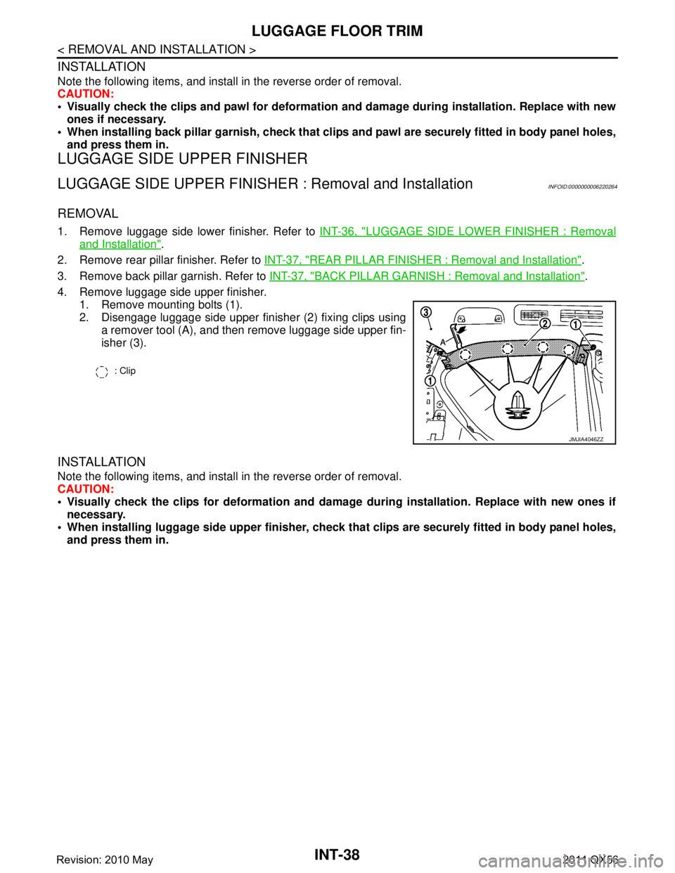
4. Remove luggage side upper finisher. 1. Remove mounting bolts (1).
2. Disengage luggage side upper finisher (2) fixing clips usinga remover tool (A), and then remove luggage side upper fin-
isher (3).
INSTALLATION
Note the following items, and install in the reverse order of removal.
CAUTION:
Visually check the clips for deformation and dama ge during installation. Replace with new ones if
necessary.
When installing luggage side uppe r finisher, check that clips are securely fitted in body panel holes,
and press them in.
: Clip
JMJIA4046ZZ
Revision: 2010 May2011 QX56
Page 3390 of 5598

BACK DOOR TRIMINT-41
< REMOVAL AND INSTALLATION >
C
DE
F
G H
I
K L
M A
B
INT
N
O P
2. Remove back door finisher inner lower.
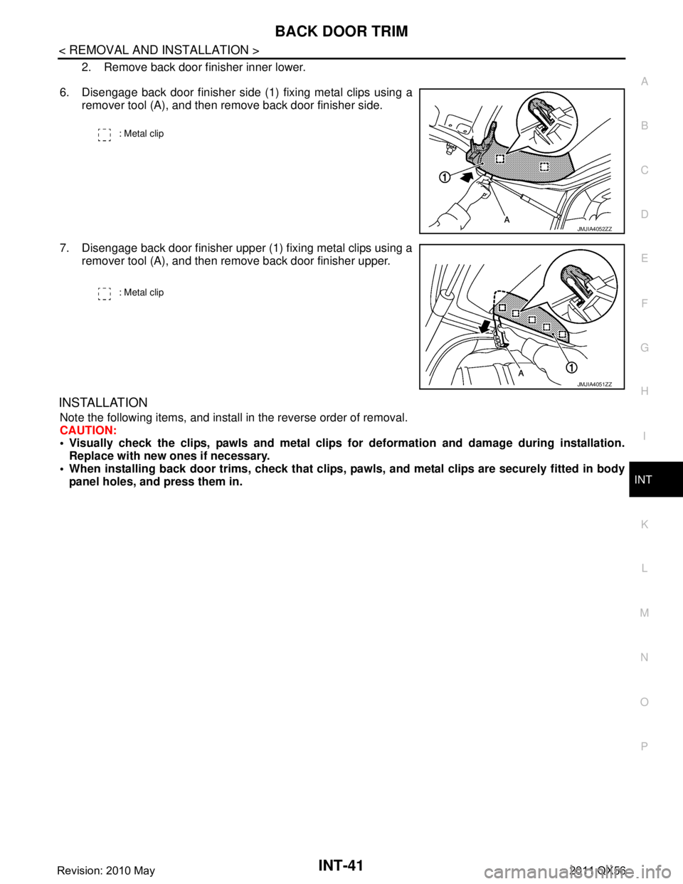
6. Disengage back door finisher side (1) fixing metal clips using a remover tool (A), and then remove back door finisher side.
7. Disengage back door finisher upper (1) fixing metal clips using a remover tool (A), and then remove back door finisher upper.
INSTALLATION
Note the following items, and install in the reverse order of removal.
CAUTION:
Visually check the clips, pawls and metal clips for deformation and damage during installation.
Replace with new ones if necessary.
When installing back door trims, check that clips, pawls, and metal clips are securely fitted in body
panel holes, and press them in.
: Metal clip
JMJIA4052ZZ
: Metal clip
JMJIA4051ZZ
Revision: 2010 May2011 QX56
Page 3398 of 5598

IP-8
< SYMPTOM DIAGNOSIS >
SQUEAK AND RATTLE TROUBLE DIAGNOSES
If possible, drive the vehicle with the customer until the noise is duplicated. Note any additional information on
the Diagnostic Worksheet regarding the conditions or lo cation of the noise. This information can be used to
duplicate the same conditions when the repair is reconfirmed.
If the noise can be duplicated easily during the test dr ive, do the following with the vehicle stopped to help
identify the source of the noise.
1) Close a door.
2) Tap or push/pull around the area where the noise appears to be coming from.
3) Rev the engine.
4) Use a floor jack to recreate vehicle “twist”.
5) At idle, apply engine load (electrical load, half-cl utch on M/T models, drive position on A/T models).
6) Raise the vehicle on a hoist and hit a tire with a rubber hammer.
Drive the vehicle and attempt to duplicate the conditions the customer states exist when the noise occurs.
If it is difficult to duplicate the noise, drive the v ehicle slowly on an undulating or rough road to stress the
vehicle body.
CHECK RELATED SERVICE BULLETINS
After verifying the customer concern or symptom, chec k ASIST for Technical Service Bulletins (TSBs) related
to the concern or symptom.
If a TSB relates to the symptom, follo w the procedure to repair the noise.
LOCATE THE NOISE AND IDENTIFY THE ROOT CAUSE
1. Narrow down the noise to a general area. To help pi npoint the source of the noise, use a listening tool
(Chassis ear: J-39570, engine ear, and mechanics stethoscope).
2. Narrow down the noise to a more specific area and identify the cause of the noise by:
Removing the component(s) in the area(s) that is / are suspected to be the cause of the noise.
Do not use too much force when removing clips and fasteners, otherwise clips and fasteners can be broken
or lost during the repair, creating a new noise.
Tapping or pushing/pulling the component(s) that is / are suspected to be the cause of the noise.
Do not tap or push/pull the component(s) with excessive force, otherwise the noise is eliminated only tempo-
rarily.
Feeling for a vibration by hand by touching the component(s ) that is / are suspected to be the cause of the
noise.
Placing a piece of paper between components that are suspected to be the cause of the noise.
Looking for loose components and contact marks. Refer to IP-9, "
Inspection Procedure".
REPAIR THE CAUSE
If the cause is a loose component, tighten the component securely.
If the cause is insufficient clearance between components:
- Separate components by repositioning or loos ening and retightening the components, if possible.
- Insulate components with a suitable insulator such as urethane pads, foam blocks, felt cloth tape, or ure-
thane tape. A NISSAN Squeak and Rattle Kit (J-43980) is available through the authorized NISSAN Parts
Department.
CAUTION:
Never use excessive force as many components are constructed of plastic and may be damaged.
NOTE:
Always check with the Parts Departm ent for the latest parts information.
The following materials are contained in the NISSAN Squeak and Rattle Kit (J-43980). Each item can be
ordered separately as needed.
URETHANE PADS [1.5 mm (0.059 in) thick]
Insulates connectors, harness, etc.
76268-9E005: 100 ×135 mm (3.937 ×5.315 in)
76884-71L01: 60 ×85 mm (2.362 ×3.346 in)
76884-71L02: 15 ×25 mm (0.591 ×0.984 in)
INSULATOR (Foam blocks)
Insulates components from contact. Can be used to fill space behind a panel.
73982-9E000: 45 mm (1.772 in) thick, 50 ×50 mm (1.969 ×1.969 in)
73982-50Y00: 10 mm (0.394 in) thick, 50 ×50 mm (1.969 ×1.969 in)
INSULATOR (Light foam block)
80845-71L00: 30 mm (1.18 in) thick, 30 ×50 mm (1.181 ×1.969in)
FELT CLOTHTAPE
Revision: 2010 May2011 QX56
Page 3400 of 5598

IP-10
< SYMPTOM DIAGNOSIS >
SQUEAK AND RATTLE TROUBLE DIAGNOSES
1. Trunk lid dumpers out of adjustment
2. Trunk lid striker out of adjustment
3. Trunk lid torsion bars knocking together
4. A loose license plate or bracket
Most of these incidents can be repaired by adjusting, securing, or insulating the item(s) or component(s) caus-
ing the noise.
SUNROOF/HEADLINING
Noises in the sunroof / headlining area can often be traced to one of the following items:
1. Sunroof lid, rail, linkage, or seals making a rattle or light knocking noise
2. Sunvisor shaft shaking in the holder
3. Front or rear windshield touching headlining and squeaking
Again, pressing on the components to stop the noise while duplicating the conditions can isolate most of these
incidents. Repairs usually consist of insulating with felt cloth tape.
SEATS
When isolating seat noise it is important to note t he position the seat is in and the load placed on the seat
when the noise occurs. These conditions should be duplic ated when verifying and isolating the cause of the
noise.
Causes of seat noise include:
1. Headrest rods and holder
2. A squeak between the seat pad cushion and frame
3. The rear seatback lock and bracket
These noises can be isolated by moving or pressing on the suspected components while duplicating the con-
ditions under which the noise occurs. Most of thes e incidents can be repaired by repositioning the component
or applying urethane tape to the contact area.
UNDERHOOD
Some interior noise may be caused by components under the hood or on the engine wall. The noise is then
transmitted into the passenger compartment.
Causes of transmitted underhood noise include:
1. Any component mounted to the engine wall
2. Components that pass through the engine wall
3. Engine wall mounts and connectors
4. Loose radiator mounting pins
5. Hood bumpers out of adjustment
6. Hood striker out of adjustment
These noises can be difficult to isolate since they cannot be reached from the interior of the vehicle. The best
method is to secure, move, or insulate one component at a time and test drive the vehicle. Also, engine RPM
or load can be changed to isolate the noise. Repairs can usually be made by moving, adjusting, securing, or
insulating the component causing the noise.
Revision: 2010 May2011 QX56
Page 3423 of 5598

LAN
LAN-3
C
DE
F
G H
I
J
K L
B
A
O P
N
Precaution for Supplemental Restraint System
(SRS) "AIR BAG" and "SEAT BELT PRE-TEN-
SIONER" .............................................................
..
102
SYSTEM DESCRIPTION ...........................103
COMPONENT PARTS ................................... ..103
Component Parts Location .................................. ..103
SYSTEM ...........................................................104
System Description ............................................. ..104
DIAGNOSIS SYSTEM (CAN GATEWAY) .......105
CONSULT-III Function ........................................ ..105
ECU DIAGNOSIS INFORMATION ............106
CAN GATEWAY ............................................. ..106
Reference Value ................................................. ..106
DTC Inspection Priority Chart .............................106
DTC Index ............................................................106
WIRING DIAGRAM ....................................108
CAN GATEWAY SYSTEM ............................. ..108
Wiring Diagram ................................................... ..108
BASIC INSPECTION .................................110
ADDITIONAL SERVICE WHEN REPLACING
CAN GATEWAY ............................................. ..
110
Description .......................................................... ..110
Work Procedure ....................................................110
CONFIGURATION (CAN GATEWAY) .............111
Description .......................................................... ..111
Work Procedure ....................................................111
DTC/CIRCUIT DIAGNOSIS .......................113
U1000 CAN COMM CIRCUIT ......................... ..113
Description .......................................................... ..113
DTC Logic .............................................................113
Diagnosis Procedure .............................................113
U1010 CONTROL UNIT (CAN) ........................114
Description .......................................................... ..114
DTC Logic .............................................................114
Diagnosis Procedure .............................................114
B2600 CONFIG ERROR ..................................115
Description .......................................................... ..115
DTC Logic .............................................................115
Diagnosis Procedure .............................................115
POWER SUPPLY AND GROUND CIRCUIT ....116
Diagnosis Procedure ........................................... ..116
REMOVAL AND INSTALLATION .............117
CAN GATEWAY ............................................. ..117
Removal and Installation ..................................... ..117
CAN SYSTEM (TYPE 1)
DTC/CIRCUIT DIAGNOSIS .......................
118
MAIN LINE BETWEEN ABS AND DLC CIR-
CUIT ................................................................
118
Diagnosis Procedure ........................................... ..118
MAIN LINE BETWEEN DLC AND E-SUS CIR-
CUIT ................................................................
119
Diagnosis Procedure .............................................119
MAIN LINE BETWEEN E-SUS AND ADP CIR-
CUIT ................................................................
120
Diagnosis Procedure .............................................120
ECM BRANCH LINE CIRCUIT .......................121
Diagnosis Procedure .............................................121
ABS BRANCH LINE CIRCUIT ........................122
Diagnosis Procedure .............................................122
TCM BRANCH LINE CIRCUIT ........................123
Diagnosis Procedure .............................................123
A-BAG BRANCH LINE CIRCUIT ....................124
Diagnosis Procedure .............................................124
AV BRANCH LINE CIRCUIT ..........................125
Diagnosis Procedure .............................................125
BCM BRANCH LINE CIRCUIT .......................126
Diagnosis Procedure .............................................126
DLC BRANCH LINE CIRCUIT ........................127
Diagnosis Procedure .............................................127
HVAC BRANCH LINE CIRCUIT .....................128
Diagnosis Procedure .............................................128
M&A BRANCH LINE CIRCUIT .......................129
Diagnosis Procedure .............................................129
STRG BRANCH LINE CIRCUIT .....................130
Diagnosis Procedure .............................................130
TPMS BRANCH LINE CIRCUIT .....................131
Diagnosis Procedure .............................................131
IPDM-E BRANCH LINE CIRCUIT ...................132
Diagnosis Procedure .............................................132
ADP BRANCH LINE CIRCUIT ........................133
Diagnosis Procedure .............................................133
E-SUS BRANCH LINE CIRCUIT ....................134
Diagnosis Procedure .............................................134
PWBD BRANCH LINE CIRCUIT ....................135
Diagnosis Procedure .............................................135
CAN COMMUNICATION CIRCUIT .................136
Diagnosis Procedure .............................................136
Revision: 2010 May2011 QX56
Page 3443 of 5598
![INFINITI QX56 2011 Factory Service Manual
LAN
HOW TO USE THIS SECTIONLAN-23
< HOW TO USE THIS MANUAL > [CAN]
C
D
E
F
G H
I
J
K L
B A
O P
N
HOW TO USE THIS MANUAL
HOW TO USE THIS SECTION
CautionINFOID:0000000006220525
This section describes INFINITI QX56 2011 Factory Service Manual
LAN
HOW TO USE THIS SECTIONLAN-23
< HOW TO USE THIS MANUAL > [CAN]
C
D
E
F
G H
I
J
K L
B A
O P
N
HOW TO USE THIS MANUAL
HOW TO USE THIS SECTION
CautionINFOID:0000000006220525
This section describes](/manual-img/42/57033/w960_57033-3442.png)
LAN
HOW TO USE THIS SECTIONLAN-23
< HOW TO USE THIS MANUAL > [CAN]
C
D
E
F
G H
I
J
K L
B A
O P
N
HOW TO USE THIS MANUAL
HOW TO USE THIS SECTION
CautionINFOID:0000000006220525
This section describes information peculiar to a vehicle and inspection procedures.
For trouble diagnosis procedure, refer to
LAN-18, "
Trouble Diagnosis Procedure".
Abbreviation ListINFOID:0000000006220526
Unit name abbreviations in CONSULT-III CAN diagnosis and in this section are as per the following list.
Abbreviation Unit name
4WD Transfer control unit
A-BAG Air bag diagnosis sensor unit ABS ABS actuator and electric unit (control unit)
ADP Driver seat control unit AFS AFS control unitAPA Accelerator pedal actuator AV AV control unit
BCM BCM
CGW CAN gateway DLC Data link connector
E-SUS Air levelizer control module ECM ECM
HVAC A/C auto amp. ICC ADAS control unit
IPDM-E IPDM E/R LANE Lane camera unit
LASER ICC sensor M&A Combination meter
PSB Pre-crash seat belt control unit (driver side)
PWBD Automatic back door control module
RDR-L Side radar LH
RDR-R Side radar RH STRG Steering angle sensor TCM TCM
TPMS Low tire pressure warning control unit
Revision: 2010 May2011 QX56
Page 3525 of 5598
![INFINITI QX56 2011 Factory Service Manual
LAN
DIAGNOSIS SYSTEM (CAN GATEWAY)LAN-105
< SYSTEM DESCRIPTION > [CAN GATEWAY]
C
D
E
F
G H
I
J
K L
B A
O P
N
DIAGNOSIS SYSTEM (CAN GATEWAY)
CONSULT-III FunctionINFOID:0000000006220576
APPLICATION ITE INFINITI QX56 2011 Factory Service Manual
LAN
DIAGNOSIS SYSTEM (CAN GATEWAY)LAN-105
< SYSTEM DESCRIPTION > [CAN GATEWAY]
C
D
E
F
G H
I
J
K L
B A
O P
N
DIAGNOSIS SYSTEM (CAN GATEWAY)
CONSULT-III FunctionINFOID:0000000006220576
APPLICATION ITE](/manual-img/42/57033/w960_57033-3524.png)
LAN
DIAGNOSIS SYSTEM (CAN GATEWAY)LAN-105
< SYSTEM DESCRIPTION > [CAN GATEWAY]
C
D
E
F
G H
I
J
K L
B A
O P
N
DIAGNOSIS SYSTEM (CAN GATEWAY)
CONSULT-III FunctionINFOID:0000000006220576
APPLICATION ITEM
CONSULT-III performs the following functi
ons via CAN communication with CAN gateway.
SELF DIAGNOSTIC RESULT
Refer to LAN-106, "DTCIndex".
Diagnosis mode Function Description
Ecu Identification The CAN gateway part number is displayed.
Self Diagnostic Result Displays the diagnosis results judged by CAN gateway.
CAN Diag Support Monitor The results of transmit/receive diagnosis of CAN communication can be read.
Configuration Read and save the vehicle specification.
Write the vehicle specification when replacing CAN gateway.
Revision: 2010 May2011 QX56
Page 3526 of 5598
![INFINITI QX56 2011 Factory Service Manual
LAN-106
< ECU DIAGNOSIS INFORMATION >[CAN GATEWAY]
CAN GATEWAY
ECU DIAGNOSIS INFORMATION
CAN GATEWAY
Reference ValueINFOID:0000000006220577
TERMINAL LAYOUT
PHYSICAL VALUES
DTC Inspection Priority Cha INFINITI QX56 2011 Factory Service Manual
LAN-106
< ECU DIAGNOSIS INFORMATION >[CAN GATEWAY]
CAN GATEWAY
ECU DIAGNOSIS INFORMATION
CAN GATEWAY
Reference ValueINFOID:0000000006220577
TERMINAL LAYOUT
PHYSICAL VALUES
DTC Inspection Priority Cha](/manual-img/42/57033/w960_57033-3525.png)
LAN-106
< ECU DIAGNOSIS INFORMATION >[CAN GATEWAY]
CAN GATEWAY
ECU DIAGNOSIS INFORMATION
CAN GATEWAY
Reference ValueINFOID:0000000006220577
TERMINAL LAYOUT
PHYSICAL VALUES
DTC Inspection Priority ChartINFOID:0000000006220578
If some DTCs are displayed at the same time, perfo
rm inspections one by one based on the following priority
chart.
DTC IndexINFOID:0000000006220579
NOTE:
JSGIA0023ZZ
Te r m i n a l N o .
(Wire color) Description
Condition Va l u e
(Approx.)
Signal name Input/
Output
+–
1
(L) —CAN-H (CAN commu-
nication circuit 1) Input/
Output ——
3
(Y) Ground Battery power supply Input Ignition switch OFF Battery voltage
4
(L) —
CAN-H (CAN commu-
nication circuit 2) Input/
Output ——
5
(B) Ground Ground — Ignition switch ON 0 V
6
(L) —CAN-H (CAN commu-
nication circuit 2) Input/
Output ——
7
(P) —
CAN-L (CAN commu-
nication circuit 1) Input/
Output ——
9
(GR) Ground Ignition power supply Input Ignition switch ON Battery voltage
10
(R) —CAN-L (CAN commu-
nication circuit 2) Input/
Output ——
11
(B) Ground Ground — Ignition switch ON 0 V
12
(R) —CAN-L (CAN commu-
nication circuit 2) Input/
Output ——
Priority DTC
1 B2600: CONFIG ERROR
U1010: CONTROL UNIT(CAN)
2 U1000: CAN COMM CIRCUIT
Revision: 2010 May2011 QX56