2011 INFINITI QX56 ECU
[x] Cancel search: ECUPage 3151 of 5598
![INFINITI QX56 2011 Factory Service Manual
A/C AUTO AMP.HAC-45
< ECU DIAGNOSIS INFORMATION > [AUTOMATIC AIR CONDITIONING]
C
D
E
F
G H
J
K L
M A
B
HAC
N
O P
*1: With ACCS (advanced climate control system)
*2: A/C auto amp. is not used for con INFINITI QX56 2011 Factory Service Manual
A/C AUTO AMP.HAC-45
< ECU DIAGNOSIS INFORMATION > [AUTOMATIC AIR CONDITIONING]
C
D
E
F
G H
J
K L
M A
B
HAC
N
O P
*1: With ACCS (advanced climate control system)
*2: A/C auto amp. is not used for con](/manual-img/42/57033/w960_57033-3150.png)
A/C AUTO AMP.HAC-45
< ECU DIAGNOSIS INFORMATION > [AUTOMATIC AIR CONDITIONING]
C
D
E
F
G H
J
K L
M A
B
HAC
N
O P
*1: With ACCS (advanced climate control system)
*2: A/C auto amp. is not used for control.
Fail-safeINFOID:0000000006275887
FAIL-SAFE FUNCTION
If a communication error exists between the A/C auto am p., and the AV control unit and preset switch for 30
seconds or longer, air conditioning is controlled under the following conditions:
When ambient temperature is less than 3 °C (37 °F) and engine coolant temperature is less than 56 °C (133 °F)
When ambient temperature is 3 °C (37 °F) or more, or engine coolant temperature is 56 °C (133 °F) or more
DTC IndexINFOID:0000000006275888
34
(L/O) GroundRear blower motor control
signal Output Ignition switch ON
Rear fan speed: 1st
speed (manual)
37
(B) —Ground — — —
38
(G/W) Ground Rear A/C relay control signal Output Ignition
switch
ONRear blower
motor: ON
0 V
Rear blower
motor: OFF 12 V
Te r m i n a l N o .
(Wire color) Description
ConditionVa l u e
(Approx.)
+ − Signal name Input/
Output
JSIIA0096ZZ
Compressor : ON
Air outlet : DEF
Air inlet : FRE (Fresh air intake)
Blower fan speed : AUTO
Set temperature : Setting before communication error occurs
Compressor : ON
Air outlet : AUTO
Air inlet : 20% FRE (20% fresh air intake)
Blower fan speed : AUTO
Set temperature : Setting before communication error occurs
DTC Items
(CONSULT-III screen terms) Reference
U1000 CAN COMM CIRCUIT HAC-72, "
DTC Logic"
U1010 CONTROL UNIT (CAN)HAC-73, "DTC Logic"
B2578 IN-VEHICLE SENSORHAC-74, "DTC Logic"
B2579 IN-VEHICLE SENSORHAC-74, "DTC Logic"
B257B AMBIENT SENOR HAC-77, "DTC Logic"
B257C AMBIENT SENOR HAC-77, "DTC Logic"
B2581 INTAKE SENSORHAC-80, "DTC Logic"
B2582 INTAKE SENSORHAC-80, "DTC Logic"
Revision: 2010 May2011 QX56
Page 3152 of 5598
![INFINITI QX56 2011 Factory Service Manual
HAC-46
< ECU DIAGNOSIS INFORMATION >[AUTOMATIC AIR CONDITIONING]
A/C AUTO AMP.
*1: With ACCS (advanced climate control system)
*2: Perform self-diagnosis under sunshine. When performi
ng indoors, aim INFINITI QX56 2011 Factory Service Manual
HAC-46
< ECU DIAGNOSIS INFORMATION >[AUTOMATIC AIR CONDITIONING]
A/C AUTO AMP.
*1: With ACCS (advanced climate control system)
*2: Perform self-diagnosis under sunshine. When performi
ng indoors, aim](/manual-img/42/57033/w960_57033-3151.png)
HAC-46
< ECU DIAGNOSIS INFORMATION >[AUTOMATIC AIR CONDITIONING]
A/C AUTO AMP.
*1: With ACCS (advanced climate control system)
*2: Perform self-diagnosis under sunshine. When performi
ng indoors, aim a light (more than 60 W) at sunload
sensor, otherwise self-diagnosis indicates even though the sunload sensor is functioning normally.
NOTE:
If all of door motor DTCs (B2632, B2633, B2634, B2635, B2636, B2637, B2638, B2639, B263D, B263E,
B263F, B2654, B2655, B2661, B2662, B2663, B2664, B 2665, B2666, B2669, and B266A) are detected, check
door motor communication circuit. Refer to HAC-120, "
Diagnosis Procedure".
B262A*1GAS SENSOR HAC-83, "DTC Logic"
B262B*1GAS SENSORHAC-83, "DTC Logic"
B2630*2SUNLOAD SENSORHAC-86, "DTC Logic"
B2631*2SUNLOAD SENSORHAC-86, "DTC Logic"
B2632 DR AIRMIX DOOR MOT HAC-89, "DTC Logic"
B2633 DR AIRMIX DOOR MOTHAC-89, "DTC Logic"
B2634 PASS AIR MIX DOOR MOTHAC-91, "DTC Logic"
B2635 PASS AIR MIX DOOR MOTHAC-91, "DTC Logic"
B2636 DR VENT DOOR FAILHAC-93, "DTC Logic"
B2637 DR B/L DOOR FAILHAC-93, "DTC Logic"
B2638 DR D/F1 DOOR FAILHAC-93, "DTC Logic"
B2639 DR DEF DOOR FAILHAC-93, "DTC Logic"
B263D FRE DOOR FAIL HAC-95, "DTC Logic"
B263E 20P FRE DOOR FAILHAC-95, "DTC Logic"
B263F REC DOOR FAILHAC-95, "DTC Logic"
B2654 D/F2 DOOR FAILHAC-93, "DTC Logic"
B2655 B/L2 DOOR FAILHAC-93, "DTC Logic"
B2657*1GAS SENSOR CIRCUITHAC-83, "DTC Logic"
B2658*1GAS SENSOR CIRCUITHAC-83, "DTC Logic"
B2661 UPPER VENT DOOR MOT HAC-97, "DTC Logic"
B2662 UPPER VENT DOOR MOTHAC-97, "DTC Logic"
B2663 UPPER VENT DOOR MOTHAC-97, "DTC Logic"
B2664 REAR AIR MIX DOOR MOTHAC-99, "DTC Logic"
B2665 REAR AIR MIX DOOR MOTHAC-99, "DTC Logic"
B2666 REAR MODE DOOR MOTHAC-101, "DTC Logic"
B2667*2PASS SUNLOAD SENSORHAC-103, "DTC Logic"
B2668*2PASS SUNLOAD SENSORHAC-103, "DTC Logic"
B2669 REAR MODE DOOR MOT HAC-101, "DTC Logic"
B266A REAR MODE DOOR MOT HAC-101, "DTC Logic"
B266B REAR IN-VEHICLE SENHAC-106, "DTC Logic"
B266C REAR IN-VEHICLE SEN HAC-106, "DTC Logic"
B27B0 A/C AUTO AMP.HAC-109, "DTC Logic"
DTCItems
(CONSULT-III screen terms) Reference
Revision: 2010 May2011 QX56
Page 3153 of 5598
![INFINITI QX56 2011 Factory Service Manual
ECM, IPDM E/RHAC-47
< ECU DIAGNOSIS INFORMATION > [AUTOMATIC AIR CONDITIONING]
C
D
E
F
G H
J
K L
M A
B
HAC
N
O P
ECM, IPDM E/R
List of ECU ReferenceINFOID:0000000006275889
ECU Reference
ECM EC-72, "
INFINITI QX56 2011 Factory Service Manual
ECM, IPDM E/RHAC-47
< ECU DIAGNOSIS INFORMATION > [AUTOMATIC AIR CONDITIONING]
C
D
E
F
G H
J
K L
M A
B
HAC
N
O P
ECM, IPDM E/R
List of ECU ReferenceINFOID:0000000006275889
ECU Reference
ECM EC-72, "](/manual-img/42/57033/w960_57033-3152.png)
ECM, IPDM E/RHAC-47
< ECU DIAGNOSIS INFORMATION > [AUTOMATIC AIR CONDITIONING]
C
D
E
F
G H
J
K L
M A
B
HAC
N
O P
ECM, IPDM E/R
List of ECU ReferenceINFOID:0000000006275889
ECU Reference
ECM EC-72, "
Reference Value"
EC-93, "Fail-safe"
EC-96, "DTC Inspection Priority Chart"
EC-98, "DTC Index"
IPDM E/R
PCS-15, "
Reference Value"
PCS-21, "Fail-Safe"
PCS-22, "DTCIndex"
Revision: 2010 May2011 QX56
Page 3268 of 5598

INL-1
DRIVER CONTROLS
C
DE
F
G H
I
J
K
M
SECTION INL
A
B
INL
N
O P
CONTENTS
INTERIOR LIGHTING SYSTEM
PRECAUTION ................ ...............................3
PRECAUTIONS .............................................. .....3
Precaution for Supplemental Restraint System
(SRS) "AIR BAG" and "SEAT BELT PRE-TEN-
SIONER" ............................................................. ......
3
SYSTEM DESCRIPTION ..............................4
COMPONENT PARTS ................................... .....4
Component Parts Location .................................. ......4
Component Description ............................................4
SYSTEM ..............................................................6
INTERIOR ROOM LAMP CONTROL SYSTEM .... ......6
INTERIOR ROOM LAMP CONTROL SYSTEM :
System Diagram ........................................................
6
INTERIOR ROOM LAMP CONTROL SYSTEM :
System Description ...................................................
6
INTERIOR ROOM LAMP BATTERY SAVER SYS-
TEM ........................................................................ ......
8
INTERIOR ROOM LAMP BATTERY SAVER
SYSTEM : System Diagram ......................................
9
INTERIOR ROOM LAMP BATTERY SAVER
SYSTEM : System Description .................................
9
ILLUMINATION CONTROL SYSTEM ................... ....10
ILLUMINATION CONTROL SYSTEM : System
Diagram ...................................................................
10
ILLUMINATION CONTROL SYSTEM : System
Description ..............................................................
10
AUTO LIGHT ADJUSTMENT SYSTEM ................ ....10
AUTO LIGHT ADJUSTMENT SYSTEM : System
Diagram ...................................................................
11
AUTO LIGHT ADJUSTMENT SYSTEM : System
Description ..............................................................
11
DIAGNOSIS SYSTEM (BCM) ............................12
COMMON ITEM ..................................................... ....12
COMMON ITEM : CONSULT-III Function (BCM -
COMMON ITEM) .....................................................
12
INT LAMP ............................................................... ....13
INT LAMP : CONSULT-III Function (BCM - INT
LAMP) ......................................................................
14
BATTERY SAVER ................................................. ....15
BATTERY SAVER : CONSULT-III Function (BCM
- BATTERY SAVER) ...............................................
15
ECU DIAGNOSIS INFO RMATION ..............17
BCM ...................................................................17
List of ECU Reference ......................................... ....17
WIRING DIAGRAM ......................................18
INTERIOR ROOM LAMP CONTROL SYSTEM
...
18
Wiring Diagram .................................................... ....18
ILLUMINATION .................................................34
Wiring Diagram ........................................................34
BASIC INSPECTION ...................................54
DIAGNOSIS AND REPAIR WORKFLOW ........54
Work Flow ............................................................ ....54
DTC/CIRCUIT DIAGNOSIS .........................56
INTERIOR ROOM LAMP POWER SUPPLY
CIRCUIT ...................... ......................................
56
Description ........................................................... ....56
Component Function Check ....................................56
Diagnosis Procedure ...............................................56
INTERIOR ROOM LAMP CONTROL CIRCUIT
...
58
Description ........................................................... ....58
Component Function Check ....................................58
Diagnosis Procedure ...............................................58
Revision: 2010 May2011 QX56
Page 3279 of 5598

INL-12
< SYSTEM DESCRIPTION >
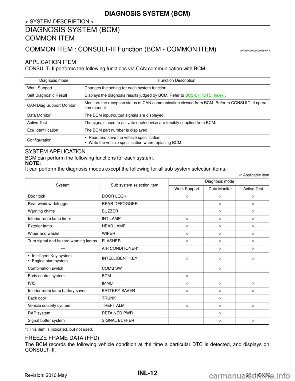
DIAGNOSIS SYSTEM (BCM)
DIAGNOSIS SYSTEM (BCM)
COMMON ITEM
COMMON ITEM : CONSULT-III Function (BCM - COMMON ITEM)INFOID:0000000006368143
APPLICATION ITEM
CONSULT-III performs the following functions via CAN communication with BCM.
SYSTEM APPLICATION
BCM can perform the following functions for each system.
NOTE:
It can perform the diagnosis modes except the following for all sub system selection items.
×: Applicable item
*: This item is indicated, but not used.
FREEZE FRAME DATA (FFD)
The BCM records the following vehicle condition at the time a particular DTC is detected, and displays on
CONSULT-III.
Diagnosis mode Function Description
Work Support Changes the setting for each system function.
Self Diagnostic Result Displays the diagnosis results judged by BCM. Refer to BCS-57, "
DTCIndex".
CAN Diag Support Monitor Monitors the reception status of CAN communication viewed from BCM. Refer to CONSULT-III opera-
tion manual.
Data Monitor The BCM input/output signals are displayed.
Active Test The signals used to activate ea ch device are forcibly supplied from BCM.
Ecu Identification The BCM part number is displayed.
Configuration Read and save the vehicle specification.
Write the vehicle specification when replacing BCM.
System Sub system selection item Diagnosis mode
Work Support Data Monitor Active Test
Door lock DOOR LOCK ×××
Rear window defogger REAR DEFOGGER ××
Warning chime BUZZER ××
Interior room lamp timer INT LAMP ×××
Exterior lamp HEAD LAMP ×××
Wiper and washer WIPER ×××
Turn signal and hazard warning lamps FLASHER ×××
— AIR CONDITONER* ××
Intelligent Key system
Engine start system INTELLIGENT KEY
×××
Combination switch COMB SW ×
Body control system BCM ×
IVIS IMMU ×××
Interior room lamp battery saver BATTERY SAVER ×××
Back door TRUNK ×
Vehicle security system THEFT ALM ×××
RAP system RETAINED PWR ×
Signal buffer system SIGNAL BUFFER ××
Revision: 2010 May2011 QX56
Page 3284 of 5598

BCM
INL-17
< ECU DIAGNOSIS INFORMATION >
C
D E
F
G H
I
J
K
M A
B
INL
N
O P
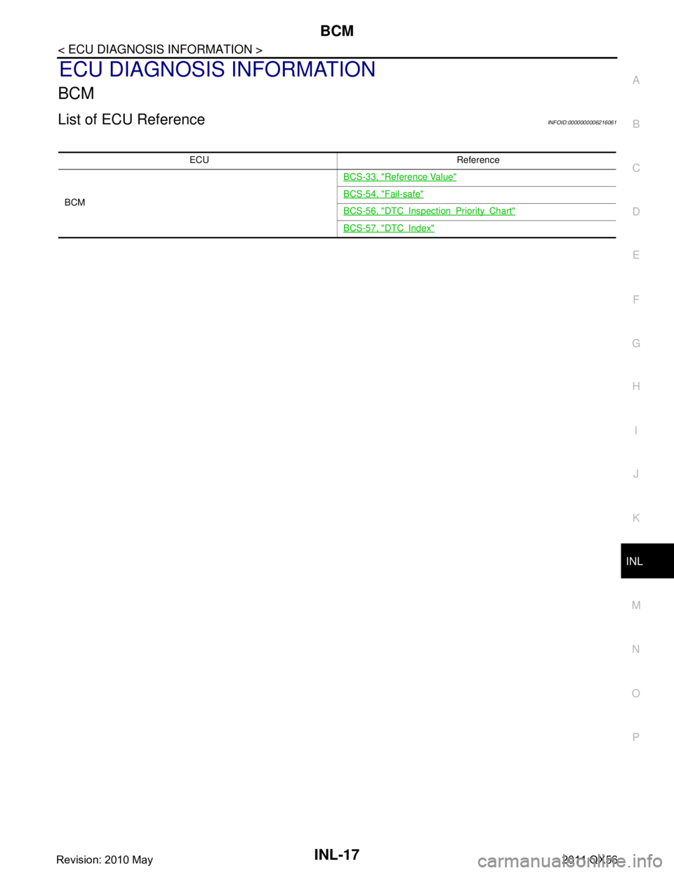
ECU DIAGNOSIS INFORMATION
BCM
List of ECU ReferenceINFOID:0000000006216061
ECU Reference
BCM BCS-33, "
Reference Value"
BCS-54, "Fail-safe"
BCS-56, "DTCInspectionPriorityChart"
BCS-57, "DTCIndex"
Revision: 2010 May2011 QX56
Page 3357 of 5598

INT-8
< SYMPTOM DIAGNOSIS >
SQUEAK AND RATTLE TROUBLE DIAGNOSES
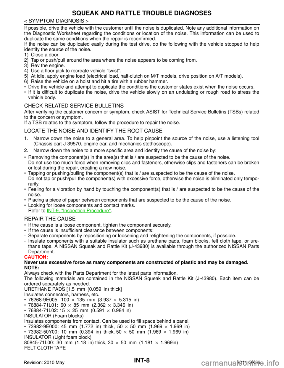
If possible, drive the vehicle with the customer until the noise is duplicated. Note any additional information on
the Diagnostic Worksheet regarding the conditions or lo cation of the noise. This information can be used to
duplicate the same conditions when the repair is reconfirmed.
If the noise can be duplicated easily during the test dr ive, do the following with the vehicle stopped to help
identify the source of the noise.
1) Close a door.
2) Tap or push/pull around the area where the noise appears to be coming from.
3) Rev the engine.
4) Use a floor jack to recreate vehicle “twist”.
5) At idle, apply engine load (electrical load, half-cl utch on M/T models, drive position on A/T models).
6) Raise the vehicle on a hoist and hit a tire with a rubber hammer.
Drive the vehicle and attempt to duplicate the conditions the customer states exist when the noise occurs.
If it is difficult to duplicate the noise, drive the v ehicle slowly on an undulating or rough road to stress the
vehicle body.
CHECK RELATED SERVICE BULLETINS
After verifying the customer concern or symptom, chec k ASIST for Technical Service Bulletins (TSBs) related
to the concern or symptom.
If a TSB relates to the symptom, follo w the procedure to repair the noise.
LOCATE THE NOISE AND IDENTIFY THE ROOT CAUSE
1. Narrow down the noise to a general area. To help pi npoint the source of the noise, use a listening tool
(Chassis ear: J-39570, engine ear, and mechanics stethoscope).
2. Narrow down the noise to a more specific area and identify the cause of the noise by:
Removing the component(s) in the area(s) that is / are suspected to be the cause of the noise.
Do not use too much force when removing clips and fasteners, otherwise clips and fasteners can be broken
or lost during the repair, creating a new noise.
Tapping or pushing/pulling the component(s) that is / are suspected to be the cause of the noise.
Do not tap or push/pull the component(s) with excessive force, otherwise the noise is eliminated only tempo-
rarily.
Feeling for a vibration by hand by touching the component(s ) that is / are suspected to be the cause of the
noise.
Placing a piece of paper between components that are suspected to be the cause of the noise.
Looking for loose components and contact marks. Refer to INT-9, "
Inspection Procedure".
REPAIR THE CAUSE
If the cause is a loose component, tighten the component securely.
If the cause is insufficient clearance between components:
- Separate components by repositioning or loos ening and retightening the components, if possible.
- Insulate components with a suitable insulator such as urethane pads, foam blocks, felt cloth tape, or ure-
thane tape. A NISSAN Squeak and Rattle Kit (J-43980) is available through the authorized NISSAN Parts
Department.
CAUTION:
Never use excessive force as many components are constructed of plastic and may be damaged.
NOTE:
Always check with the Parts Departm ent for the latest parts information.
The following materials are contained in the NISSAN Squeak and Rattle Kit (J-43980). Each item can be
ordered separately as needed.
URETHANE PADS [1.5 mm (0.059 in) thick]
Insulates connectors, harness, etc.
76268-9E005: 100 ×135 mm (3.937 ×5.315 in)
76884-71L01: 60 ×85 mm (2.362 ×3.346 in)
76884-71L02: 15 ×25 mm (0.591 ×0.984 in)
INSULATOR (Foam blocks)
Insulates components from contact. Can be used to fill space behind a panel.
73982-9E000: 45 mm (1.772 in) thick, 50 ×50 mm (1.969 ×1.969 in)
73982-50Y00: 10 mm (0.394 in) thick, 50 ×50 mm (1.969 ×1.969 in)
INSULATOR (Light foam block)
80845-71L00: 30 mm (1.18 in) thick, 30 ×50 mm (1.181 ×1.969in)
FELT CLOTHTAPE
Revision: 2010 May2011 QX56
Page 3359 of 5598

INT-10
< SYMPTOM DIAGNOSIS >
SQUEAK AND RATTLE TROUBLE DIAGNOSES
1. Trunk lid dumpers out of adjustment
2. Trunk lid striker out of adjustment
3. Trunk lid torsion bars knocking together
4. A loose license plate or bracket
Most of these incidents can be repaired by adjusting, securing, or insulating the item(s) or component(s) caus-
ing the noise.
SUNROOF/HEADLINING
Noises in the sunroof / headlining area can often be traced to one of the following items:
1. Sunroof lid, rail, linkage, or seals making a rattle or light knocking noise
2. Sunvisor shaft shaking in the holder
3. Front or rear windshield touching headlining and squeaking
Again, pressing on the components to stop the noise while duplicating the conditions can isolate most of these
incidents. Repairs usually consist of insulating with felt cloth tape.
SEATS
When isolating seat noise it is important to note t he position the seat is in and the load placed on the seat
when the noise occurs. These conditions should be duplic ated when verifying and isolating the cause of the
noise.
Causes of seat noise include:
1. Headrest rods and holder
2. A squeak between the seat pad cushion and frame
3. The rear seatback lock and bracket
These noises can be isolated by moving or pressing on the suspected components while duplicating the con-
ditions under which the noise occurs. Most of thes e incidents can be repaired by repositioning the component
or applying urethane tape to the contact area.
UNDERHOOD
Some interior noise may be caused by components under the hood or on the engine wall. The noise is then
transmitted into the passenger compartment.
Causes of transmitted underhood noise include:
1. Any component mounted to the engine wall
2. Components that pass through the engine wall
3. Engine wall mounts and connectors
4. Loose radiator mounting pins
5. Hood bumpers out of adjustment
6. Hood striker out of adjustment
These noises can be difficult to isolate since they cannot be reached from the interior of the vehicle. The best
method is to secure, move, or insulate one component at a time and test drive the vehicle. Also, engine RPM
or load can be changed to isolate the noise. Repairs can usually be made by moving, adjusting, securing, or
insulating the component causing the noise.
Revision: 2010 May2011 QX56