2011 INFINITI QX56 ECU
[x] Cancel search: ECUPage 2954 of 5598
FSU-12
< REMOVAL AND INSTALLATION >
FRONT COIL SPRING AND SHOCK ABSORBER
When installing the shock absorber attachment to shock absorber, wrap a shop cloth around
shock absorber to protect it from damage.
2. Compress coil spring using a spring compressor (commercial service tool), and install it onto shock absorber.
CAUTION:
Be sure a spring compressor is securely attach ed to coil spring. Compress coil spring.
Set coil spring so that its paint marks face downward.
3. Apply soapy water to dust cover. CAUTION:
Never use machine oil.
4. Install dust cover, bound bumper cover, rubber seat , bushings, tube, shock absorber mounting bracket,
and washer to shock absorber.
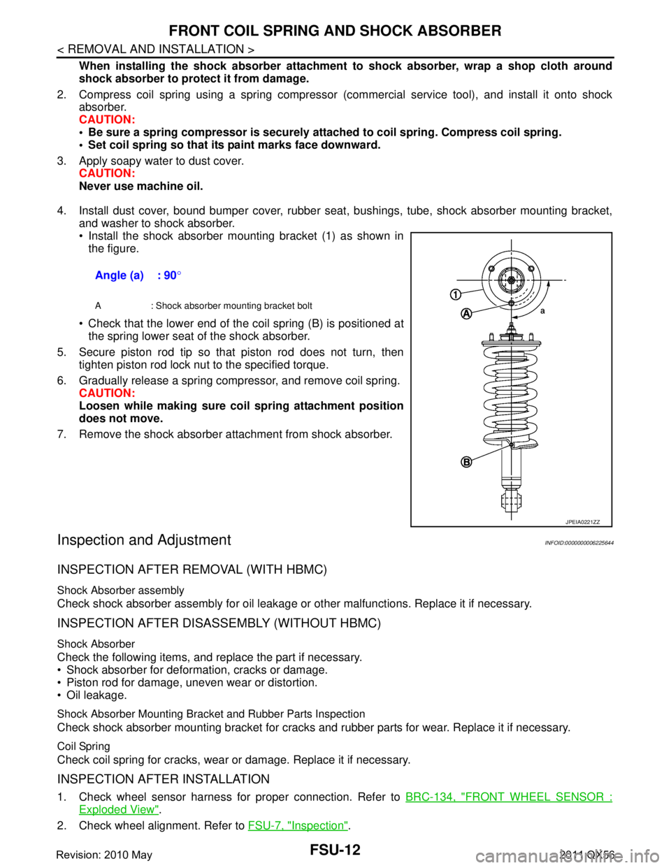
Install the shock absorber mounting bracket (1) as shown in the figure.
Check that the lower end of the coil spring (B) is positioned at the spring lower seat of the shock absorber.
5. Secure piston rod tip so that piston rod does not turn, then tighten piston rod lock nut to the specified torque.
6. Gradually release a spring compressor, and remove coil spring. CAUTION:
Loosen while making sure co il spring attachment position
does not move.
7. Remove the shock absorber attachment from shock absorber.
Inspection and AdjustmentINFOID:0000000006225644
INSPECTION AFTER REMOVAL (WITH HBMC)
Shock Absorber assembly
Check shock absorber assembly for oil leakage or other malfunctions. Replace it if necessary.
INSPECTION AFTER DISASSEMBLY (WITHOUT HBMC)
Shock Absorber
Check the following items, and replace the part if necessary.
Shock absorber for deformation, cracks or damage.
Piston rod for damage, uneven wear or distortion.
Oil leakage.
Shock Absorber Mounting Bracket and Rubber Parts Inspection
Check shock absorber mounting bracket for cracks and rubber parts for wear. Replace it if necessary.
Coil Spring
Check coil spring for cracks, wear or damage. Replace it if necessary.
INSPECTION AFTER INSTALLATION
1. Check wheel sensor harness for proper connection. Refer to BRC-134, "FRONT WHEEL SENSOR :
Exploded View".
2. Check wheel alignment. Refer to FSU-7, "
Inspection".
Angle (a) : 90
°
A : Shock absorber mounting bracket bolt
JPEIA0221ZZ
Revision: 2010 May2011 QX56
Page 2957 of 5598
LOWER LINKFSU-15
< REMOVAL AND INSTALLATION >
C
DF
G H
I
J
K L
M A
B
FSU
N
O P
12. Separate drive shaft from steering knuckle. (4WD) Refer to FAX-22, "Removal and Installation".
13. Remove lower link from steering knuckle. Refer to FA X - 8 , "
Removal and Installation" (2WD), FAX-18,
"Removal and Installation" (4WD).
14. Remove protector A. (With HBMC) Refer to SCS-32, "
FRONT TUBE ASSEMBLY : Removal and Installa-
tion".
15. Remove bracket. (With HBMC) Refer to SCS-32, "
FRONT TUBE ASSEMBLY : Removal and Installation".
16. Remove adjusting bolts, nuts, eccentric discs, stopper rubber, and lower link from vehicle.
17. Remove bump rubber from lower link.
18. Perform inspection after removal. Refer to FSU-15, "
Inspection".
INSTALLATION
Note the following, and install in the reverse order of removal.
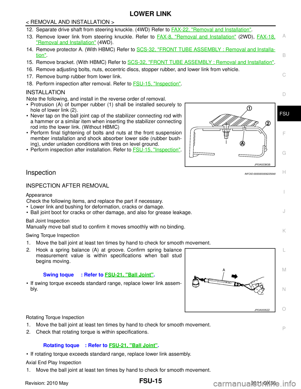
Protrusion (A) of bumper rubber (1) shall be installed securely to
hole of lower link (2).
Never tap on the ball joint cap of the stabilizer connecting rod with a hammer or a similar item when inserting the stabilizer connecting
rod into the lower link. (Without HBMC)
Perform final tightening of bolts and nuts at the front suspension member installation and shock absorber lower side (rubber bush-
ing), under unladen conditions with tires on level ground.
Perform inspection after installation. Refer to FSU-15, "
Inspection".
InspectionINFOID:0000000006225648
INSPECTION AFTER REMOVAL
Appearance
Check the following items, and replace the part if necessary.
Lower link and bushing for deformation, cracks or damage.
Ball joint boot for cracks or other damage, and also for grease leakage.
Ball Joint Inspection
Manually move ball stud to confirm it moves smoothly with no binding.
Swing Torque Inspection
1. Move the ball joint at least ten times by hand to check for smooth movement.
2. Hook a spring balance (A) at groove. Confirm spring balance
measurement value is within specifications when ball stud
begins moving.
If swing torque exceeds standard range, replace lower link assem- bly.
Rotating Torque Inspection
1. Move the ball joint at least ten times by hand to check for smooth movement.
2. Check that rotating torque is within specifications.
If rotating torque exceeds standard range, replace lower link assembly.
Axial End Play Inspection
1. Move the ball joint at least ten times by hand to check for smooth movement.
JPEIA0238GB
Swing toque : Refer to FSU-21, "Ball Joint".
JPEIA0005ZZ
Rotating toque : Refer to FSU-21, "Ball Joint".
Revision: 2010 May2011 QX56
Page 2990 of 5598
GI-26
< PRECAUTION >
PRECAUTIONS
PRECAUTION
PRECAUTIONS
DescriptionINFOID:0000000006280865
Observe the following precautions to ensure safe and proper servicing. These precautions are not
described in each individual section.
Precaution for Supplemental Restraint S ystem (SRS) "AIR BAG" and "SEAT BELT
PRE-TENSIONER"
INFOID:0000000006280866
The Supplemental Restraint System such as “A IR BAG” and “SEAT BELT PRE-TENSIONER”, used along
with a front seat belt, helps to reduce the risk or severi ty of injury to the driver and front passenger for certain
types of collision. This system includes seat belt switch inputs and dual stage front air bag modules. The SRS
system uses the seat belt switches to determine the front air bag deployment, and may only deploy one front
air bag, depending on the severity of a collision and w hether the front occupants are belted or unbelted.
Information necessary to service the system safely is included in the “SRS AIR BAG” and “SEAT BELT” of this
Service Manual.
WARNING:
To avoid rendering the SRS inopera tive, which could increase the risk of personal injury or death in
the event of a collision that would result in air bag inflation, all maintenance must be performed by
an authorized NISS AN/INFINITI dealer.
Improper maintenance, including in correct removal and installation of the SRS, can lead to personal
injury caused by unintent ional activation of the system. For re moval of Spiral Cable and Air Bag
Module, see the “SRS AIR BAG”.
Do not use electrical test equipmen t on any circuit related to the SRS unless instructed to in this
Service Manual. SRS wiring harnesses can be identi fied by yellow and/or orange harnesses or har-
ness connectors.
PRECAUTIONS WHEN USING POWER TOOLS (AIR OR ELECTRIC) AND HAMMERS
WARNING:
When working near the Air Bag Diagnosis Sensor Unit or other Air Bag System sensors with the
ignition ON or engine running, DO NOT use air or electric power tools or strike near the sensor(s)
with a hammer. Heavy vibration could activate the sensor(s) and deploy the air bag(s), possibly
causing serious injury.
When using air or electric power tools or hammers , always switch the ignition OFF, disconnect the
battery, and wait at least 3 minu tes before performing any service.
Precautions For Xenon Headlamp ServiceINFOID:0000000006280867
WARNING:
Comply with the following warnings to prevent any serious accident.
Disconnect the battery cable (negative terminal) or the power supply fuse before installing, remov-
ing, or touching the xenon headlamp (bulb included). The xenon headlamp contains high-voltage
generated parts.
Never work with wet hands.
Check the xenon headlamp ON-OFF status after assembling it to the vehicle. Never turn the xenon
headlamp ON in other conditions. Connect th e power supply to the vehicle-side connector.
(Turning it ON outside the lamp case m ay cause fire or visual impairments.)
Never touch the bulb glass immediately after turning it OFF. It is extremely hot.
CAUTION:
Comply with the following cautions to prevent any error and malfunction.
Install the xenon bulb securely. (Ins ufficient bulb socket installation may melt the bulb, the connec-
tor, the housing, etc. by high-v oltage leakage or corona discharge.)
Never perform HID circuit in spection with a tester.
Never touch the xenon bulb glass with ha nds. Never put oil and grease on it.
Dispose of the used xenon bulb after packing it in thick vinyl without breaking it.
Never wipe out dirt and cont amination with organic solven t (thinner, gasoline, etc.).
Revision: 2010 May2011 QX56
Page 2994 of 5598
GI-30
< PRECAUTION >
PRECAUTIONS
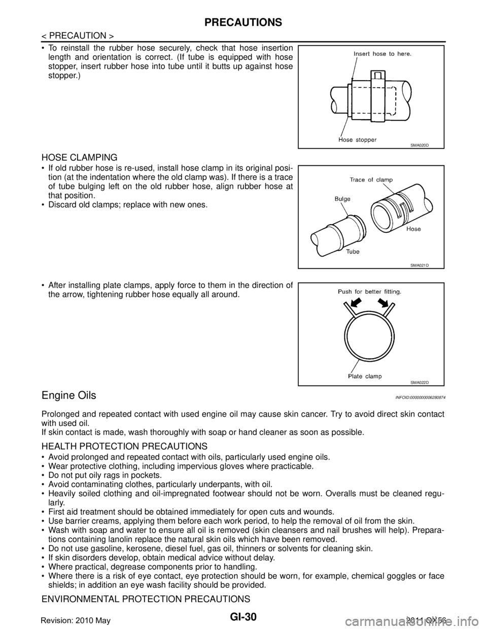
To reinstall the rubber hose securely, check that hose insertionlength and orientation is correct. (If tube is equipped with hose
stopper, insert rubber hose into tube until it butts up against hose
stopper.)
HOSE CLAMPING
If old rubber hose is re-used, install hose clamp in its original posi-tion (at the indentation where the old clamp was). If there is a trace
of tube bulging left on the old rubber hose, align rubber hose at
that position.
Discard old clamps; replace with new ones.
After installing plate clamps, apply force to them in the direction of the arrow, tightening rubber hose equally all around.
Engine OilsINFOID:0000000006280874
Prolonged and repeated contact with used engine oil may cause skin cancer. Try to avoid direct skin contact
with used oil.
If skin contact is made, wash thoroughly with soap or hand cleaner as soon as possible.
HEALTH PROTECTION PRECAUTIONS
Avoid prolonged and repeated contact with oils, particularly used engine oils.
Wear protective clothing, including impervious gloves where practicable.
Do not put oily rags in pockets.
Avoid contaminating clothes, pa rticularly underpants, with oil.
Heavily soiled clothing and oil-impregnated footwear should not be worn. Overalls must be cleaned regu-
larly.
First aid treatment should be obtained immediately for open cuts and wounds.
Use barrier creams, applying them before each work period, to help the removal of oil from the skin.
Wash with soap and water to ensure all oil is removed (skin cleansers and nail brushes will help). Prepara-
tions containing lanolin replace the natural skin oils which have been removed.
Do not use gasoline, kerosene, diesel fuel, gas oil, thinners or solvents for cleaning skin.
If skin disorders develop, obtain medical advice without delay.
Where practical, degrease components prior to handling.
Where there is a risk of eye contact, eye protection should be worn, for example, chemical goggles or face
shields; in addition an eye wash facility should be provided.
ENVIRONMENTAL PROTECTION PRECAUTIONS
SMA020D
SMA021D
SMA022D
Revision: 2010 May2011 QX56
Page 3009 of 5598
SERVICE INFORMATION FOR ELECTRICAL INCIDENTGI-45
< BASIC INSPECTION >
C
DE
F
G H
I
J
K L
M B
GI
N
O P
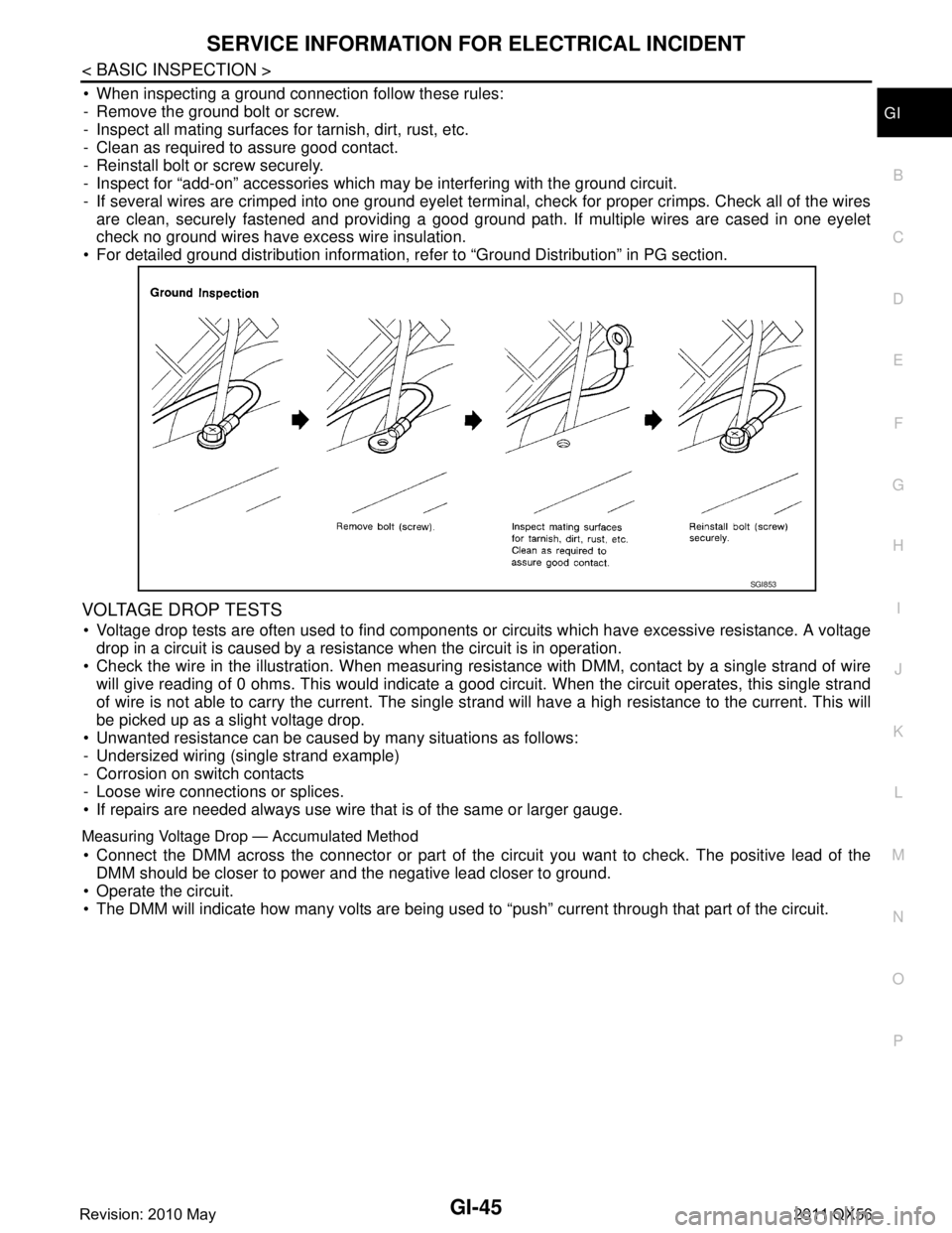
When inspecting a ground connection follow these rules:
- Remove the ground bolt or screw.
- Inspect all mating surfaces for tarnish, dirt, rust, etc.
- Clean as required to assure good contact.
- Reinstall bolt or screw securely.
- Inspect for “add-on” accessories which may be interfering with the ground circuit.
- If several wires are crimped into one ground eyelet terminal, check for proper crimps. Check all of the wires are clean, securely fastened and providing a good ground path. If multiple wires are cased in one eyelet
check no ground wires have excess wire insulation.
For detailed ground distribution information, re fer to “Ground Distribution” in PG section.
VOLTAGE DROP TESTS
Voltage drop tests are often used to find components or circuits which have excessive resistance. A voltage
drop in a circuit is caused by a resistance when the circuit is in operation.
Check the wire in the illustration. When measuring re sistance with DMM, contact by a single strand of wire
will give reading of 0 ohms. This would indicate a good circuit. When the circuit operates, this single strand
of wire is not able to carry the current. The single st rand will have a high resistance to the current. This will
be picked up as a slight voltage drop.
Unwanted resistance can be caused by many situations as follows:
- Undersized wiring (single strand example)
- Corrosion on switch contacts
- Loose wire connections or splices.
If repairs are needed always use wire that is of the same or larger gauge.
Measuring Voltage Drop — Accumulated Method
Connect the DMM across the connector or part of the ci rcuit you want to check. The positive lead of the
DMM should be closer to power and the negative lead closer to ground.
Operate the circuit.
The DMM will indicate how many volts are being used to “push” current through that part of the circuit.
SGI853
Revision: 2010 May2011 QX56
Page 3012 of 5598
GI-48
< BASIC INSPECTION >
CONSULT-III/GST CHECKING SYSTEM
CONSULT-III/GST CHECKING SYSTEM
DescriptionINFOID:0000000006280856
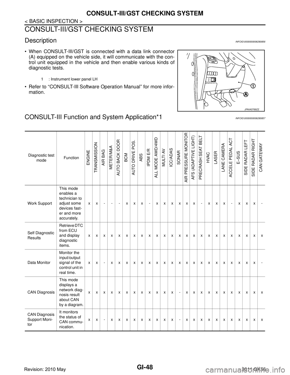
When CONSULT-III/GST is connected with a data link connector
(A) equipped on the vehicle side, it will communicate with the con-
trol unit equipped in the vehicle and then enable various kinds of
diagnostic tests.
Refer to “CONSULT-III Software Operation Manual” for more infor- mation.
CONSULT-III Function a nd System Application*1INFOID:0000000006280857
1 : Instrument lower panel LH
JPAIA0769ZZ
Diagnostic test
mode Function
ENGINE
TRANSMISSION AIR BAG
METER/M&A
AUTO BACK DOOR BCM
AUTO DRIVE POS. ABS
IPDM E/R
ALL MODE AWD/4WD MULTI AV
ICC/ADAS SONAR
AIR PRESSURE MONITOR AFS (ADAPTIVE LIGHT)
PRECRASH SEAT BELT HVAC
LASER
LANE CAMERA
ACCELE PEDAL ACT
E–SUS
SIDE RADAR LEFT
SIDE RADAR RIGHT CAN GATEWAY
Work Support This mode
enables a
technician to
adjust some
devices fast-
er and more
accurately.xx - - - xxx - xxxxxx - xxx - xxx -
Self Diagnostic
Results Retrieve DTC
from ECU
and display
diagnostic
items.
xxxxxxxxxxxxxxxxxxxxxxxx
Data Monitor Monitor the
input/output
signal of the
control unit in
real time.xx - xxxxxxxxxxxxxxxxxxxx -
CAN Diagnosis This mode
displays a
network diag-
nosis result
about CAN
by a diagram.xxxxxxxxxxxx -xxxxxxxxxxx
CAN Diagnosis
Support Moni-
tor It monitors
the status of
CAN commu-
nication.
xx - xxxxxxxxx -xxxxxxxxxxx
Revision: 2010 May2011 QX56
Page 3013 of 5598
CONSULT-III/GST CHECKING SYSTEMGI-49
< BASIC INSPECTION >
C
DE
F
G H
I
J
K L
M B
GI
N
O P
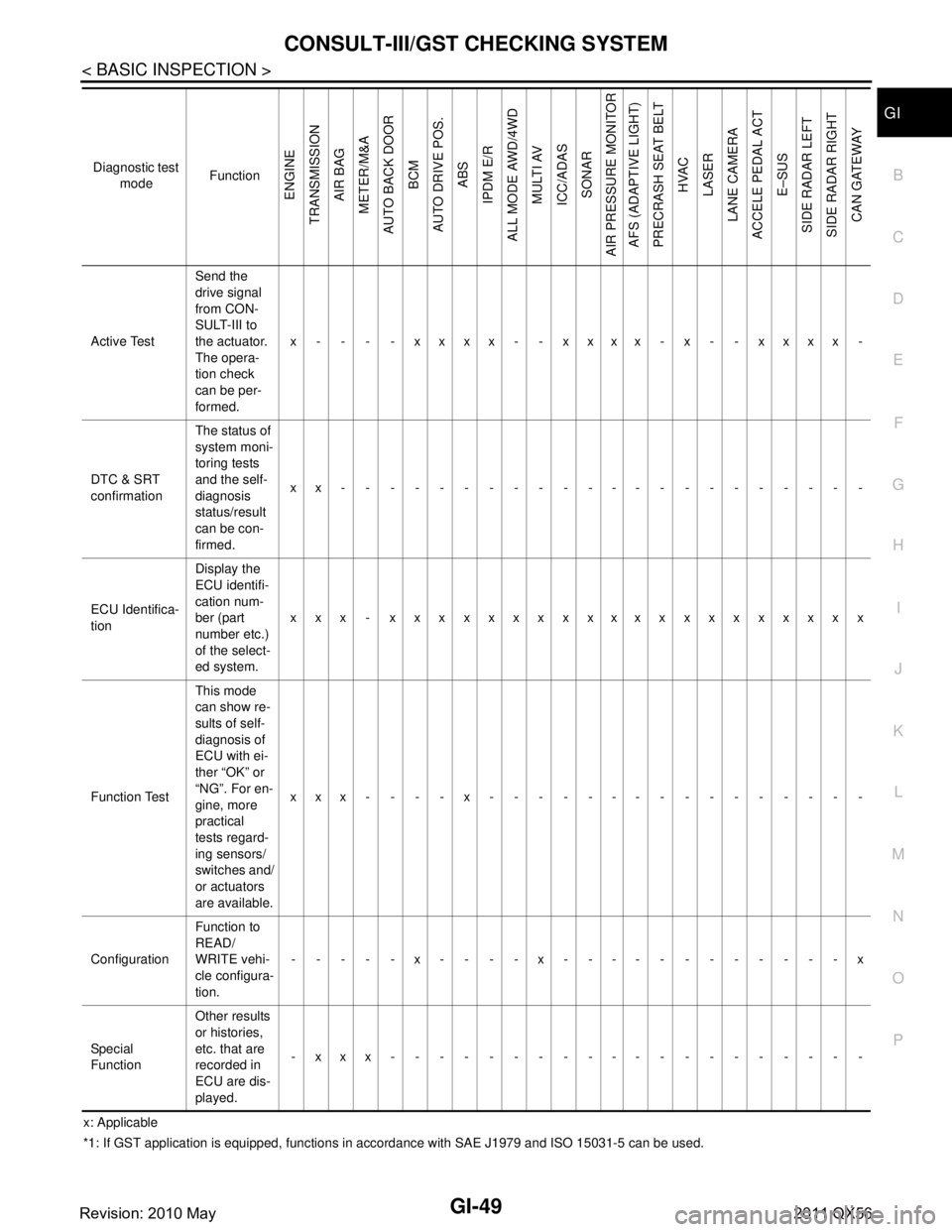
x: Applicable
*1: If GST application is equipped , functions in accordance with SAE J1 979 and ISO 15031-5 can be used.
Active Test
Send the
drive signal
from CON-
SULT-III to
the actuator.
The opera-
tion check
can be per-
formed.x - - - - xxxx - - xxxx - x - - xxxx -
DTC & SRT
confirmation The status of
system moni-
toring tests
and the self-
diagnosis
status/result
can be con-
firmed.
xx----------------------
ECU Identifica-
tion Display the
ECU identifi-
cation num-
ber (part
number etc.)
of the select-
ed system.
xxx - xxxxxxxxxxxxxxxxxxxx
Function Test This mode
can show re-
sults of self-
diagnosis of
ECU with ei-
ther “OK” or
“NG”. For en-
gine, more
practical
tests regard-
ing sensors/
switches and/
or actuators
are available.xxx----x----------------
Configuration Function to
READ/
WRITE vehi-
cle configura-
tion.-----x----x------------x
Special
Function Other results
or histories,
etc. that are
recorded in
ECU are dis-
played.
-xxx--------------------
Diagnostic test
mode Function
ENGINE
TRANSMISSION AIR BAG
METER/M&A
AUTO BACK DOOR
BCM
AUTO DRIVE POS. ABS
IPDM E/R
ALL MODE AWD/4WD
MULTI AV
ICC/ADAS SONAR
AIR PRESSURE MONITOR AFS (ADAPTIVE LIGHT)
PRECRASH SEAT BELT HVAC
LASER
LANE CAMERA
ACCELE PEDAL ACT E–SUS
SIDE RADAR LEFT
SIDE RADAR RIGHT CAN GATEWAY
Revision: 2010 May2011 QX56
Page 3030 of 5598
GW-1
BODY EXTERIOR, DOORS, ROOF & VEHICLE SECURITY
C
D
E
F
G H
I
J
L
M
SECTION GW
A
B
GW
N
O P
CONTENTS
GLASS & WINDOW SYSTEM
PRECAUTION ................ ...............................2
PRECAUTIONS .............................................. .....2
Precaution for Supplemental Restraint System
(SRS) "AIR BAG" and "SEAT BELT PRE-TEN-
SIONER" ............................................................. ......
2
Precaution Necessary for Steering Wheel Rota-
tion after Battery Disconnect .....................................
2
Precaution for Procedure without Cowl Top Cover ......3
Handling for Adhesive and Primer ............................3
PREPARATION ............................................4
PREPARATION .............................................. .....4
Special Service Tools ........................................ ......4
Commercial Service Tools .......................................4
SYMPTOM DIAGNOSIS ...............................5
SQUEAK AND RATTLE TROUBLE DIAG-
NOSES ........................ ........................................
5
Work Flow ........................................................... ......5
Inspection Procedure ................................................7
Diagnostic Worksheet ...............................................9
REMOVAL AND INSTALLATION ...............11
WINDSHIELD GLASS .................................... ....11
Exploded View .................................................... ....11
Removal and Installation .........................................12
Inspection ................................................................13
SIDE WINDOW GLASS ....................................14
Exploded View ..................................................... ....14
Removal and Installation .........................................15
Inspection ................................................................15
BACK DOOR WINDOW GLASS ......................16
Exploded View ..................................................... ....16
Removal and Installation .........................................16
Inspection ................................................................17
FRONT DOOR GLASS .....................................19
Exploded View .........................................................19
Removal and Installation .........................................19
Inspection and Adjustment ......................................20
FRONT REGULATOR .......................................21
Exploded View .........................................................21
Removal and Installation .........................................21
Disassembly and Assembly .....................................21
Inspection and Adjustment ......................................22
REAR DOOR GLASS .......................................23
Exploded View .........................................................23
Removal and Installation .........................................23
Inspection and Adjustment ......................................25
REAR REGULATOR .........................................26
Exploded View .........................................................26
Removal and Installation .........................................26
Disassembly and Assembly .....................................27
Inspection and Adjustment ......................................27
Revision: 2010 May2011 QX56