2011 INFINITI QX56 key battery
[x] Cancel search: key batteryPage 1681 of 5598

INTELLIGENT KEYDLK-145
< DTC/CIRCUIT DIAGNOSIS >
C
DE
F
G H
I
J
L
M A
B
DLK
N
O P
INTELLIGENT KEY
Component Function CheckINFOID:0000000006225961
1.CHECK FUNCTION
1. Select “INTELLIGENT KEY” of “BCM” using CONSULT-III.
2. Select “RKE OPE COUN1” in “DATA MONITOR” mode.
3. Check that the function operates normall y according to the following conditions.
Is the inspection result normal?
YES >> Intelligent Key is OK.
NO >> Refer to DLK-145, "
Diagnosis Procedure".
Diagnosis ProcedureINFOID:0000000006225962
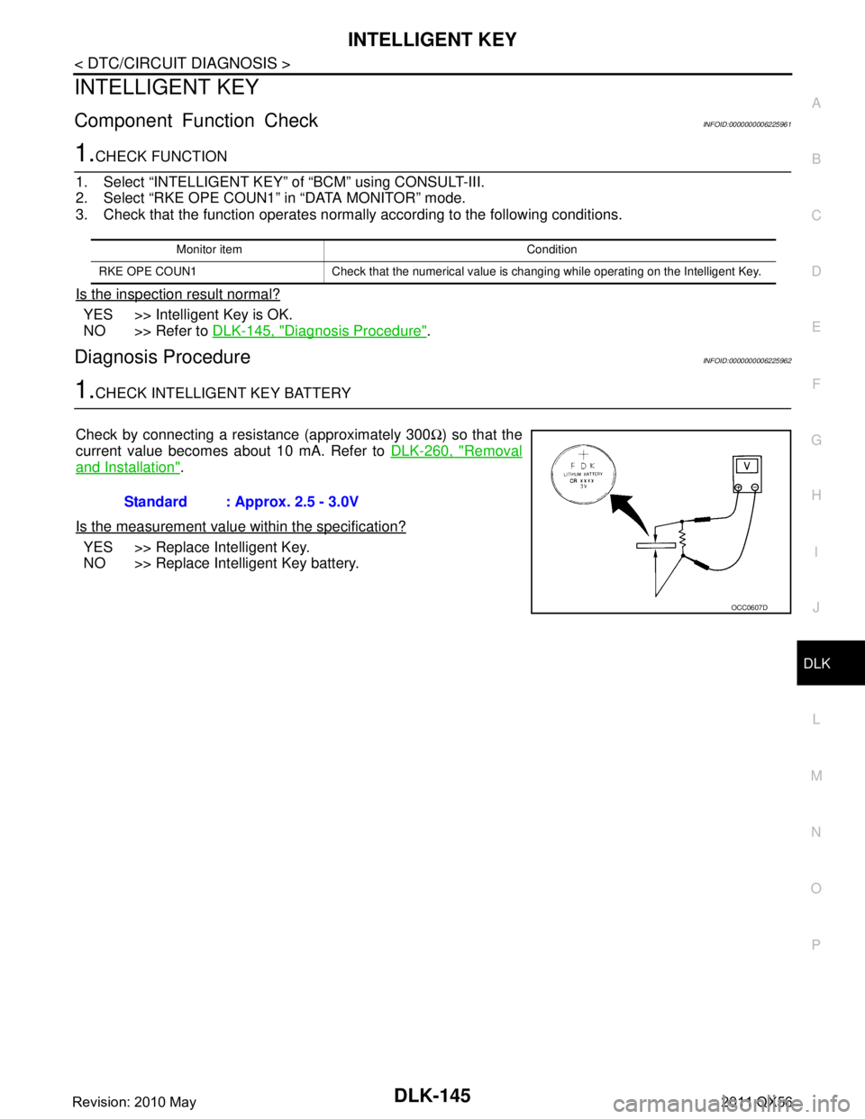
1.CHECK INTELLIGENT KEY BATTERY
Check by connecting a resistance (approximately 300 Ω) so that the
current value becomes about 10 mA. Refer to DLK-260, "
Removal
and Installation".
Is the measurement value within the specification?
YES >> Replace Intelligent Key.
NO >> Replace Intelligent Key battery.
Monitor item Condition
RKE OPE COUN1 Check that the numerical value is changing while operating on the Intelligent Key.
Standard : Approx. 2.5 - 3.0V
OCC0607D
Revision: 2010 May2011 QX56
Page 1731 of 5598

INTELLIGENT KEY LOW BATTERY WARNING DOES NOT OPERATE
DLK-195
< SYMPTOM DIAGNOSIS >
C
D E
F
G H
I
J
L
M A
B
DLK
N
O P
INTELLIGENT KEY LOW BATTERY WARNING DOES NOT OPERATE
DescriptionINFOID:0000000006226034
Intelligent Key low battery warning does not operat e for vehicle with information display models.
NOTE:
Warning functions operating condition is extremely comp licated, during operating confirmations, reconfirm the
list above twice in order to ensure proper operation. Refer to DLK-27, "
WARNING FUNCTION : System
Description".
Diagnosis ProcedureINFOID:0000000006226035
1.CHECK DTC WITH BCM
Check that DTC is not detected with BCM
Is the inspection result normal?
YES >> GO TO 2.
NO >> Perform trouble diagnosis relevant to DTC indicated.
2.CHECK DTC WITH COMBINATION METER
Check that DTC is not detected with combination meter
Is the inspection result normal?
YES >> GO TO 3.
NO >> Perform trouble diagnosis relevant to DTC indicated.
3.CHECK “LO- BATT OF KEY FOB WARN” SETTING IN “WORK SUPPORT”
1. Select “INTELLIGENT KEY” of “BCM”.
2. Select “LO- BATT OF KEY FOB WARN” in “WORK SUPPORT” mode.
3. Check “LO- BATT OF KEY FOB WARN” setting in “WORK SUPPORT”. Refer to DLK-41, "
INTELLIGENT KEY : CONSULT-III Function (BCM - INTELLIGENT KEY)".
Is the inspection result normal?
YES >> GO TO 4.
NO >> Set “ON” in “LO- BATT OF KEY FOB WARN”.
4.CHECK INTELLIGENT KEY
Check Intelligent Key.
Refer to DLK-145, "
ComponentFunctionCheck".
Is the inspection result normal?
YES >> GO TO 5.
NO >> Repair or replace the malfunctioning parts.
5.CHECK INSIDE KEY ANTENNA
Check inside key antenna.
Instrument center: Refer to DLK-104, "
DTC Logic".
Console: Refer to DLK-106, "
DTC Logic".
Luggage room: Refer to DLK-108, "
DTC Logic".
Is the inspection result normal?
YES >> GO TO 6.
NO >> Repair or replace the malfunctioning parts.
6.CHECK INFORMATION DISPLAY
Check information display.
Refer to DLK-147, "
ComponentFunctionCheck".
Is the inspection result normal?
YES >> GO TO 7.
NO >> Repair or replace the malfunctioning parts.
7.REPLACE BCM
Replace BCM. Refer to BCS-81, "
Removal and Installation".
Revision: 2010 May2011 QX56
Page 1732 of 5598

DLK-196
< SYMPTOM DIAGNOSIS >
INTELLIGENT KEY LOW BATTERY WARNING DOES NOT OPERATE
Confirm the operation after replacement.
Is the result normal?
YES >> INSPECTION END
NO >> Check intermittent incident. Refer to GI-40, "
Intermittent Incident".
Revision: 2010 May2011 QX56
Page 1796 of 5598

DLK-260
< REMOVAL AND INSTALLATION >
INTELLIGENT KEY BATTERY
INTELLIGENT KEY BATTERY
Removal and InstallationINFOID:0000000006226127
1. Release the lock knob at the back of the Intelligent Key and remove the mechanical key.
2. Insert a flat-blade screwdriver (A) wrapped with a cloth into the slit of the corner and twist it to separate the upper part from the
lower part.
CAUTION:
Do not touch the circuit board or battery terminal.
The key fob is water-resistant. However, if it does get wet,immediately wipe it dry.
3. Replace the battery with new one.
4. Align the tips of the upper and lower parts, and then push them together until it is securely closed.
CAUTION:
When replacing battery, keep dirt, grease, and other for-
eign materials off the electrode contact area.
After replacing the battery, check that all Intelligent Key
functions work normally.
PIIB6221E
Battery replacement :Coin-type lithium battery
(CR2025)
PIIB6222E
Revision: 2010 May2011 QX56
Page 2732 of 5598
![INFINITI QX56 2011 Factory Service Manual
EXL-22
< SYSTEM DESCRIPTION >[XENON TYPE]
DIAGNOSIS SYSTEM (BCM)
DIAGNOSIS SYSTEM (BCM)
COMMON ITEM
COMMON ITEM : CONSULT-III Fu
nction (BCM - COMMON ITEM)INFOID:0000000006368037
APPLICATION ITEM
CON INFINITI QX56 2011 Factory Service Manual
EXL-22
< SYSTEM DESCRIPTION >[XENON TYPE]
DIAGNOSIS SYSTEM (BCM)
DIAGNOSIS SYSTEM (BCM)
COMMON ITEM
COMMON ITEM : CONSULT-III Fu
nction (BCM - COMMON ITEM)INFOID:0000000006368037
APPLICATION ITEM
CON](/manual-img/42/57033/w960_57033-2731.png)
EXL-22
< SYSTEM DESCRIPTION >[XENON TYPE]
DIAGNOSIS SYSTEM (BCM)
DIAGNOSIS SYSTEM (BCM)
COMMON ITEM
COMMON ITEM : CONSULT-III Fu
nction (BCM - COMMON ITEM)INFOID:0000000006368037
APPLICATION ITEM
CONSULT-III performs the following functions via CAN communication with BCM.
SYSTEM APPLICATION
BCM can perform the following functions for each system.
NOTE:
It can perform the diagnosis modes except the following for all sub system selection items.
×: Applicable item
*: This item is indicated, but not used.
FREEZE FRAME DATA (FFD)
The BCM records the following vehicle condition at the time a particular DTC is detected, and displays on
CONSULT-III.
Diagnosis mode Function Description
Work Support Changes the setting for each system function.
Self Diagnostic Result Displays the diagnosis results judged by BCM. Refer to BCS-57, "
DTCIndex".
CAN Diag Support Monitor Monitors the reception status of CAN communication viewed from BCM. Refer to CONSULT-III opera-
tion manual.
Data Monitor The BCM input/output signals are displayed.
Active Test The signals used to activate ea ch device are forcibly supplied from BCM.
Ecu Identification The BCM part number is displayed.
Configuration Read and save the vehicle specification.
Write the vehicle specification when replacing BCM.
System Sub system selection item Diagnosis mode
Work Support Data Monitor Active Test
Door lock DOOR LOCK ×××
Rear window defogger REAR DEFOGGER ××
Warning chime BUZZER ××
Interior room lamp timer INT LAMP ×××
Exterior lamp HEAD LAMP ×××
Wiper and washer WIPER ×××
Turn signal and hazard warning lamps FLASHER ×××
— AIR CONDITONER* ××
Intelligent Key system
Engine start system INTELLIGENT KEY
×××
Combination switch COMB SW ×
Body control system BCM ×
IVIS IMMU ×××
Interior room lamp battery saver BATTERY SAVER ×××
Back door TRUNK ×
Vehicle security system THEFT ALM ×××
RAP system RETAINED PWR ×
Signal buffer system SIGNAL BUFFER ××
Revision: 2010 May2011 QX56
Page 2965 of 5598

GI-1
GENERAL INFORMATION
C
DE
F
G H
I
J
K L
M B
GI
SECTION GI
N
O P
CONTENTS
GENERAL INFORMATION
HOW TO USE THIS MANU AL ......................3
HOW TO USE THIS MANUAL ....................... .....3
Description .......................................................... ......3
Terms ........................................................................3
Units ..........................................................................3
Contents ....................................................................3
Relation between Illustrations and Descriptions .......4
Components ..............................................................4
HOW TO FOLLOW TROUBLE DIAGNOSES .....6
Description ................................................................6
How to Follow Test Groups in Trouble Diagnosis ......6
Key to Symbols Signifying Measurements or Pro-
cedures ............................................................... ......
7
HOW TO READ WIRING DIAGRAMS ................9
Connector Symbols ............................................. ......9
Sample/Wiring Diagram -Example- .........................10
Connector Information .............................................12
ABBREVIATIONS .......................................... ....14
Abbreviation List .................................................. ....14
TIGHTENING TORQUE OF STANDARD
BOLTS ................................................................
19
Description .......................................................... ....19
Tightening Torque Table (New Standard Includ-
ed) ...........................................................................
19
RECOMMENDED CHEMICAL PRODUCTS
AND SEALANTS ................................................
22
Recommended Chemical Products and Sealants ....22
VEHICLE INFORMATION ............................23
IDENTIFICATION INFORMATION ................. ....23
Model Variation ................................................... ....23
Information About Identification or Model Code ......23
Dimensions .............................................................25
Wheels & Tires ........................................................25
PRECAUTION ..............................................26
PRECAUTIONS .................................................26
Description ........................................................... ....26
Precaution for Supplemental Restraint System
(SRS) "AIR BAG" and "SEAT BELT PRE-TEN-
SIONER" .................................................................
26
Precautions For Xenon Headlamp Service .............26
Precaution Necessary for Steering Wheel Rota-
tion after Battery Disconnect ...................................
27
Precaution for Procedure without Cowl Top Cover ....27
General Precautions ................................................27
Three Way Catalyst .................................................29
Multiport Fuel Injection System or Engine Control
System .....................................................................
29
Hoses ......................................................................29
Engine Oils ..............................................................30
Air Conditioning .......................................................31
Fuel ..........................................................................31
LIFTING POINT .................................................32
Pantograph Jack ......................................................32
Garage Jack and Safety Stand ................................32
2-Pole Lift ................................................................33
TOW TRUCK TOWING .....................................34
Tow Truck Towing ...................................................34
Vehicle Recovery (Freeing a Stuck Vehicle) ...........34
BASIC INSPECTION ...................................36
SERVICE INFORMATION FOR ELECTRICAL
INCIDENT ..........................................................
36
Work Flow ............................................................ ....36
Control Units and Electrical Parts ............................36
How to Check Terminal ...........................................37
Intermittent Incident .................................................40
Circuit Inspection .....................................................43
CONSULT-III/GST CHECKING SYSTEM .........48
Description ...............................................................48
CONSULT-III Function and System Application*1 ....48
Revision: 2010 May2011 QX56
Page 2993 of 5598

PRECAUTIONSGI-29
< PRECAUTION >
C
DE
F
G H
I
J
K L
M B
GI
N
O P
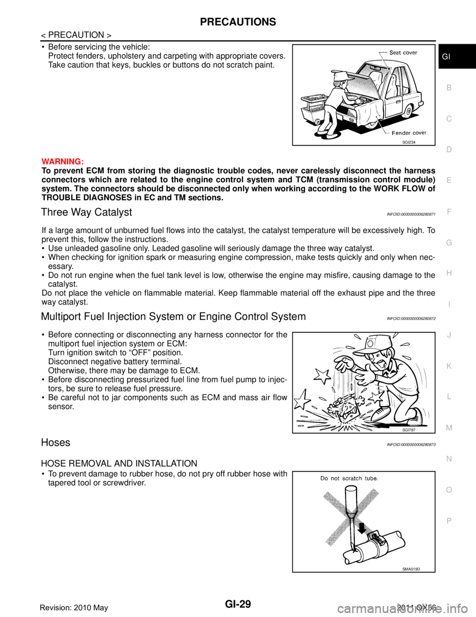
Before servicing the vehicle: Protect fenders, upholstery and carpeting with appropriate covers.
Take caution that keys, buckles or buttons do not scratch paint.
WARNING:
To prevent ECM from storing the diagnostic trou ble codes, never carelessly disconnect the harness
connectors which are related to the engine cont rol system and TCM (transmission control module)
system. The connectors should be disconnected only when working according to the WORK FLOW of
TROUBLE DIAGNOSES in EC and TM sections.
Three Way CatalystINFOID:0000000006280871
If a large amount of unburned fuel flows into the catalyst , the catalyst temperature will be excessively high. To
prevent this, follow the instructions.
Use unleaded gasoline only. Leaded gasoline will seriously damage the three way catalyst.
When checking for ignition spark or measuring engine compression, make tests quickly and only when nec- essary.
Do not run engine when the fuel tank level is low, otherwise the engine may misfire, causing damage to the
catalyst.
Do not place the vehicle on flammable material. Keep flammable material off the exhaust pipe and the three
way catalyst.
Multiport Fuel Inje ction System or Engine Control SystemINFOID:0000000006280872
Before connecting or disconnecti ng any harness connector for the
multiport fuel injection system or ECM:
Turn ignition switch to “OFF” position.
Disconnect negative battery terminal.
Otherwise, there may be damage to ECM.
Before disconnecting pressurized fuel line from fuel pump to injec- tors, be sure to release fuel pressure.
Be careful not to jar components such as ECM and mass air flow sensor.
HosesINFOID:0000000006280873
HOSE REMOVAL AND INSTALLATION
To prevent damage to rubber hose, do not pry off rubber hose withtapered tool or screwdriver.
SGI234
SGI787
SMA019D
Revision: 2010 May2011 QX56
Page 3000 of 5598

GI-36
< BASIC INSPECTION >
SERVICE INFORMATION FOR ELECTRICAL INCIDENT
BASIC INSPECTION
SERVICE INFORMATION FOR ELECTRICAL INCIDENT
Work FlowINFOID:0000000006280851
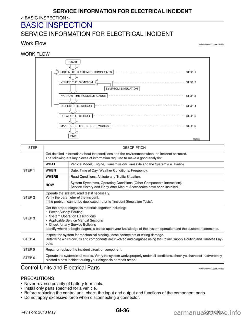
WORK FLOW
Control Units and Electrical PartsINFOID:0000000006280852
PRECAUTIONS
Never reverse polarity of battery terminals.
Install only parts specified for a vehicle.
Before replacing the control unit, check the i nput and output and functions of the component parts.
Do not apply excessive force when disconnecting a connector.
SGI838
STEP DESCRIPTION
STEP 1 Get detailed information about the conditions and the environment when the incident occurred.
The following are key pieces of information required to make a good analysis:
WHAT
Vehicle Model, Engine, Transmission/Transaxle and the System (i.e. Radio).
WHEN Date, Time of Day, Weather Conditions, Frequency.
WHERE Road Conditions, Altitude and Traffic Situation.
HOW System Symptoms, Operating Conditions
(Other Components Interaction).
Service History and if any After Market Accessories have been installed.
STEP 2 Operate the system, road test if necessary.
Verify the parameter of the incident.
If the problem cannot be duplicated, refer to “Incident Simulation Tests”.
STEP 3 Get the proper diagnosis materials together including:
Power Supply Routing
System Operation Descriptions
Applicable Service Manual Sections
Check for any Service Bulletins
Identify where to begin diagnosis based upon your knowledge of the system operation and the customer comments.
STEP 4 Inspect the system for mechanical binding, loose connectors or wiring damage.
Determine which circuits and components are involved and diagnose using the Power Supply Routing and Harness Lay-
outs.
STEP 5 Repair or replace the incident circuit or component.
STEP 6 Operate the system in all modes. Verify the system works properly under all conditions. check you have not inadvertently
created a new incident during your diagnosis or repair steps.
Revision: 2010 May2011 QX56