2011 INFINITI QX56 turn signal
[x] Cancel search: turn signalPage 1482 of 5598
![INFINITI QX56 2011 Factory Service Manual
DAS
WARNING SYSTEMS ON INDICATOR CIRCUITDAS-517
< DTC/CIRCUIT DIAGNOSIS > [BSW]
C
D
E
F
G H
I
J
K L
M B
N P A
WARNING SYSTEMS ON INDICATOR CIRCUIT
Component Function CheckINFOID:0000000006223974
1.CH INFINITI QX56 2011 Factory Service Manual
DAS
WARNING SYSTEMS ON INDICATOR CIRCUITDAS-517
< DTC/CIRCUIT DIAGNOSIS > [BSW]
C
D
E
F
G H
I
J
K L
M B
N P A
WARNING SYSTEMS ON INDICATOR CIRCUIT
Component Function CheckINFOID:0000000006223974
1.CH](/manual-img/42/57033/w960_57033-1481.png)
DAS
WARNING SYSTEMS ON INDICATOR CIRCUITDAS-517
< DTC/CIRCUIT DIAGNOSIS > [BSW]
C
D
E
F
G H
I
J
K L
M B
N P A
WARNING SYSTEMS ON INDICATOR CIRCUIT
Component Function CheckINFOID:0000000006223974
1.CHECK WARNING SYSTEMS ON INDICATOR
1. Turn the ignition switch ON.
2. Select the active test item “WARNING SY STEM IND” of “ICC/ADAS” with CONSULT-III.
3. With operating the test item, check the operation.
Is the inspection result normal?
YES >> INSPECTION END
NO >> Refer to DAS-517, "
Diagnosis Procedure".
Diagnosis ProcedureINFOID:0000000006223975
1.CHECK WARNING ON INDICATOR POWER SUPPLY CIRCUIT
1. Turn ignition switch OFF.
2. Disconnect twin switch connector.
3. Turn ignition switch ON.
4. Check voltage between twin switch harness connector and ground.
Is the inspection result normal?
YES >> GO TO 2.
NO >> Repair the warning systems ON indicator power supply circuit.
2.CHECK WARNING SYSTEMS ON INDICATOR SIGNAL FOR OPEN
1. Turn ignition switch OFF.
2. Disconnect the ADAS control unit harness connector.
3. Check continuity between the ADAS control uni t harness connector and twin switch harness connector.
Is the inspection result normal?
YES >> GO TO 3.
NO >> Repair the harnesses or connectors.
3.CHECK WARNING SYSTEMS ON INDI CATOR SIGNAL CIRCUIT FOR SHORT
Check continuity between the ADAS control unit harness connector and ground.
Is the inspection result normal?
YES >> GO TO 4. On : Warning systems ON indicator illuminates
Off : Warning systems ON in
dicator is turned OFF
Te r m i n a l s
Vo l ta g e
(Approx.)
(+) (
−)
Twin switch Ground
Connector Terminal
M127 8 Battery voltage
ADAS control unit Twin switch Continuity
Connector Terminal Connector Terminal
B61 4 M127 9 Existed
ADAS control unit
GroundContinuity
Connector Terminal
B61 4 Not existed
Revision: 2010 May2011 QX56
Page 1484 of 5598
![INFINITI QX56 2011 Factory Service Manual
DAS
WARNING BUZZER CIRCUITDAS-519
< DTC/CIRCUIT DIAGNOSIS > [BSW]
C
D
E
F
G H
I
J
K L
M B
N P A
WARNING BUZZER CIRCUIT
Component Function CheckINFOID:0000000006223977
1.CHECK WARNING BUZZER
1. Turn t INFINITI QX56 2011 Factory Service Manual
DAS
WARNING BUZZER CIRCUITDAS-519
< DTC/CIRCUIT DIAGNOSIS > [BSW]
C
D
E
F
G H
I
J
K L
M B
N P A
WARNING BUZZER CIRCUIT
Component Function CheckINFOID:0000000006223977
1.CHECK WARNING BUZZER
1. Turn t](/manual-img/42/57033/w960_57033-1483.png)
DAS
WARNING BUZZER CIRCUITDAS-519
< DTC/CIRCUIT DIAGNOSIS > [BSW]
C
D
E
F
G H
I
J
K L
M B
N P A
WARNING BUZZER CIRCUIT
Component Function CheckINFOID:0000000006223977
1.CHECK WARNING BUZZER
1. Turn the ignition switch ON.
2. Select the active test item “LDP BU ZZER” of “ICC/ADAS” with CONSULT-III.
3. With operating the test item, check the operation.
Is the inspection result normal?
YES >> INSPECTION END
NO >> Refer to DAS-393, "
Diagnosis Procedure".
Diagnosis ProcedureINFOID:0000000006223978
1.CHECK WARNING BUZZER POWER SUPPLY CIRCUIT
1. Turn ignition switch OFF.
2. Disconnect the warning buzzer connector.
3. Turn ignition switch ON.
4. Check voltage between the warning buzzer harness connector and ground.
Is the inspection result normal?
YES >> GO TO 2.
NO >> Repair the warning buzzer power supply circuit.
2.CHECK WARNING BUZZER GROUND CIRCUIT
1. Turn ignition switch OFF.
2. Check continuity between the warning buzzer harness connector and ground.
Is the inspection result normal?
YES >> GO TO 3.
NO >> Repair the harnesses or connectors.
3.CHECK WARNING BUZZER SIGNAL CIRCUIT FOR OPEN
1. Disconnect the ADAS control unit connector.
2. Check continuity between the ADAS control uni t harness connector and warning buzzer harness connec-
tor.
Is the inspection result normal?
On : Warning buzzer is activated.
Off : Warning buzzer is not activated.
Te r m i n a l s Vo l ta g e
(Approx.)
(+) (
−)
Warning buzzer Ground
Connector Terminal
M94 1 Battery voltage
Warning buzzer GroundContinuity
Connector Terminal
M94 3 Existed
ADAS control unit Warning buzzer Continuity
Connector Terminal Connector Terminal
B61 12 M94 2 Existed
Revision: 2010 May2011 QX56
Page 1485 of 5598
![INFINITI QX56 2011 Factory Service Manual
DAS-520
< DTC/CIRCUIT DIAGNOSIS >[BSW]
WARNING BUZZER CIRCUIT
YES >> GO TO 4.
NO >> Repair the harnesses or connectors.
4.CHECK WARNING BUZZER SIGNAL CIRCUIT FOR SHORT
Check continuity between the AD INFINITI QX56 2011 Factory Service Manual
DAS-520
< DTC/CIRCUIT DIAGNOSIS >[BSW]
WARNING BUZZER CIRCUIT
YES >> GO TO 4.
NO >> Repair the harnesses or connectors.
4.CHECK WARNING BUZZER SIGNAL CIRCUIT FOR SHORT
Check continuity between the AD](/manual-img/42/57033/w960_57033-1484.png)
DAS-520
< DTC/CIRCUIT DIAGNOSIS >[BSW]
WARNING BUZZER CIRCUIT
YES >> GO TO 4.
NO >> Repair the harnesses or connectors.
4.CHECK WARNING BUZZER SIGNAL CIRCUIT FOR SHORT
Check continuity between the ADAS control unit harness connector and ground.
Is the inspection result normal?
YES >> GO TO 5.
NO >> Repair the harnesses or connectors.
5.CHECK WARNING BUZZER OPERATION
1. Connect the warning buzzer connector.
2. Turn ignition switch ON.
3. Apply ground to warning buzzer terminal 2.
4. Check condition of the warning buzzer.
Does warning buzzer sound?
YES >> Replace the ADAS control unit.
NO >> Replace the warning buzzer.
ADAS control unit
GroundContinuity
Connector Terminal
M61 12 Not existed
Revision: 2010 May2011 QX56
Page 1486 of 5598
![INFINITI QX56 2011 Factory Service Manual
DAS
BSW SYSTEM SYMPTOMSDAS-521
< SYMPTOM DIAGNOSIS > [BSW]
C
D
E
F
G H
I
J
K L
M B
N P A
SYMPTOM DIAGNOSIS
BSW SYSTEM SYMPTOMS
Symptom TableINFOID:0000000006223979
CAUTION:
Perform the self-diagnosis INFINITI QX56 2011 Factory Service Manual
DAS
BSW SYSTEM SYMPTOMSDAS-521
< SYMPTOM DIAGNOSIS > [BSW]
C
D
E
F
G H
I
J
K L
M B
N P A
SYMPTOM DIAGNOSIS
BSW SYSTEM SYMPTOMS
Symptom TableINFOID:0000000006223979
CAUTION:
Perform the self-diagnosis](/manual-img/42/57033/w960_57033-1485.png)
DAS
BSW SYSTEM SYMPTOMSDAS-521
< SYMPTOM DIAGNOSIS > [BSW]
C
D
E
F
G H
I
J
K L
M B
N P A
SYMPTOM DIAGNOSIS
BSW SYSTEM SYMPTOMS
Symptom TableINFOID:0000000006223979
CAUTION:
Perform the self-diagnosis with CONS ULT-III before the symptom diagnosis. Perform the trouble diag-
nosis if any DTC is detected.
NOTE:
For the operational conditions of BSW, refer to DAS-410, "
System Description".
Symptom Possible cause Inspection item/Reference page
Indicator/warning lamps do not il-
luminate when ignition switch
OFF ⇒ ON. BSW warning lamp (Yellow)
does not illuminate
BSW warning lamp signal
(CAN)
- Combination meter
- ADAS control unit
BSW warning lamp (combina- tion meter) ADAS control unit Active test
“BSW/BSI WARNING LAMP”
Refer to DAS-419, "
CON-
SULT-III Function (ICC/
ADAS)".
ADAS control unit Data moni-
tor “BSW/BSI WARN LMP”
Refer to DAS-419, "
CON-
SULT-III Function (ICC/
ADAS)"
Combination meter Data mon-
itor “BSW W/L”
Refer to MWI-30, "
CONSULT-
III Function"
All of indicator/warning
lamps do not illuminate;
BSW warning lamp
Warning systems ON indi-
cator Power supply and ground cir-
cuit of ADAS control unit
ADAS control unit
Combination meter Power supply and ground circuit
of ADAS control unit
Refer to
DAS-512, "
ADAS CON-
TROL UNIT : Diagnosis Proce-
dure"
Warning systems ON indica-
tor (on the warning systems
switch) does not illuminate Harness between ADAS con-
trol unit and warning systems
switch
Warning systems switch
ADAS control unit Warning systems ON indicator
circuit
Refer to
DAS-517, "
Diagnosis
Procedure"
BSW indicator does not turn
ON Harness between side radar
and BSW indicator
Side radar LH/RH
BSW indicator Perform self-diagnosis of side ra-
dar
Refer to
DAS-429, "CONSULT-III
Function (SIDE RADAR LEFT)"
or DAS-431, "
CONSULT-III Func-
tion (SIDE RADAR RIGHT)".
BSW system is not activated.
(Indicator/warning lamps illumi-
nate when ignition switch OFF ⇒
ON.) Warning systems ON indica-
tor is not turned ON
⇔ OFF
when operating warning sys-
tems switch Harness between ADAS con-
trol unit and waning systems
switch
Harness between warning
systems switch and ground
ADAS control unit
Warning systems switch Warning systems ON indicator
circuit
Refer to
DAS-517, "
Diagnosis
Procedure".
Buzzer is not sounding Buzzer power supply circuit
Harness between ADAS con-
trol unit and warning buzzer
Harness between warning
buzzer and ground
Warning buzzer
ADAS control unit Warning buzzer circuit
Refer to
DAS-519, "
Diagnosis
Procedure"
Revision: 2010 May2011 QX56
Page 1497 of 5598

COMPONENT PARTSDEF-5
< SYSTEM DESCRIPTION >
C
DE
F
G H
I
J
K
M A
B
DEF
N
O P
SYSTEM DESCRIPTION
COMPONENT PARTS
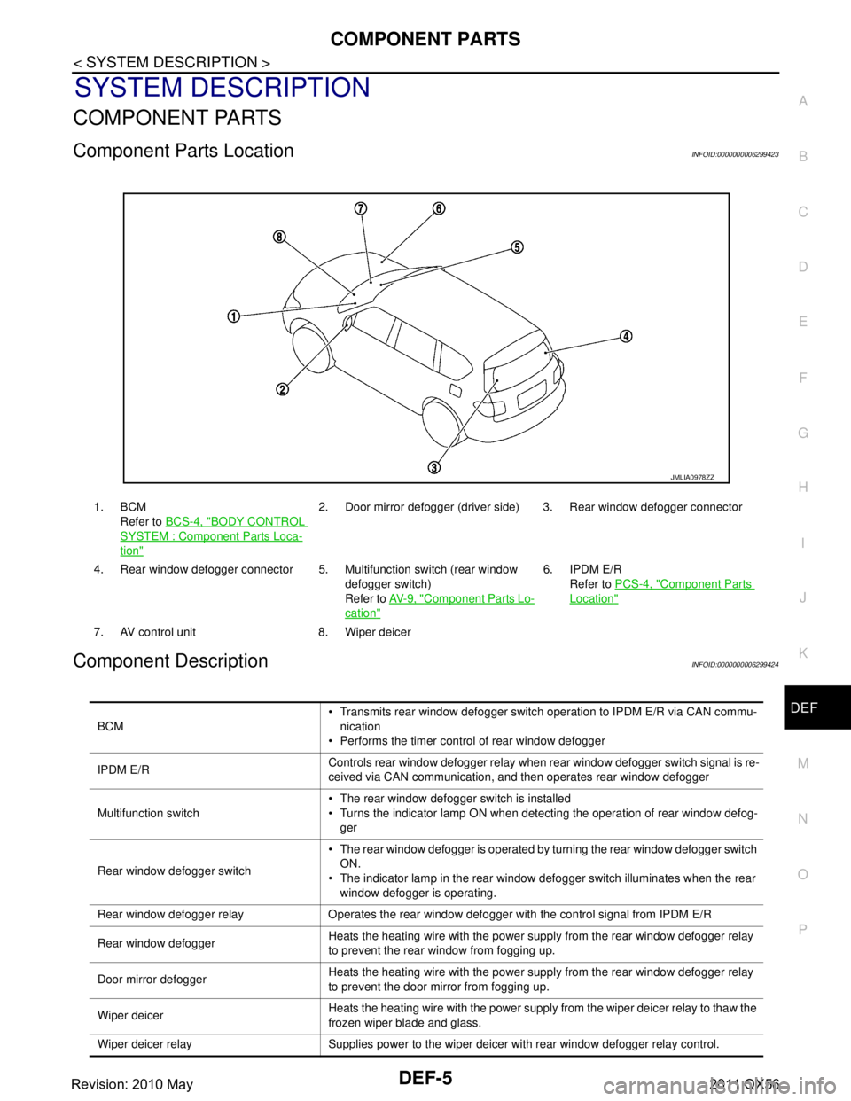
Component Parts LocationINFOID:0000000006299423
Component DescriptionINFOID:0000000006299424
1. BCM Refer to BCS-4, "
BODY CONTROL
SYSTEM : Component Parts Loca-
tion"
2. Door mirror defogger (driver side) 3. Rear window defogger connector
4. Rear window defogger connector 5. Multifunction switch (rear window defogger switch)
Refer to AV- 9 , "
Component Parts Lo-
cation"
6. IPDM E/R
Refer to PCS-4, "
Component Parts
Location"
7. AV control unit 8. Wiper deicer
JMLIA0978ZZ
BCM Transmits rear window defogger switch operation to IPDM E/R via CAN commu-
nication
Performs the timer control of rear window defogger
IPDM E/R Controls rear window defogger relay when rear window defogger switch signal is re-
ceived via CAN communication, and then operates rear window defogger
Multifunction switch The rear window defogger switch is installed
Turns the indicator lamp ON when detecting the operation of rear window defog-
ger
Rear window defogger switch The rear window defogger is operated by turning the rear window defogger switch
ON.
The indicator lamp in the rear window defogger switch illuminates when the rear window defogger is operating.
Rear window defogger relay Operates the rear window defogger with the control signal from IPDM E/R
Rear window defogger Heats the heating wire with the power supply from the rear window defogger relay
to prevent the rear window from fogging up.
Door mirror defogger Heats the heating wire with the power supply from the rear window defogger relay
to prevent the door mirror from fogging up.
Wiper deicer Heats the heating wire with the power supply from the wiper deicer relay to thaw the
frozen wiper blade and glass.
Wiper deicer relay Supplies power to the wiper deicer with rear window defogger relay control.
Revision: 2010 May2011 QX56
Page 1498 of 5598

DEF-6
< SYSTEM DESCRIPTION >
SYSTEM
SYSTEM
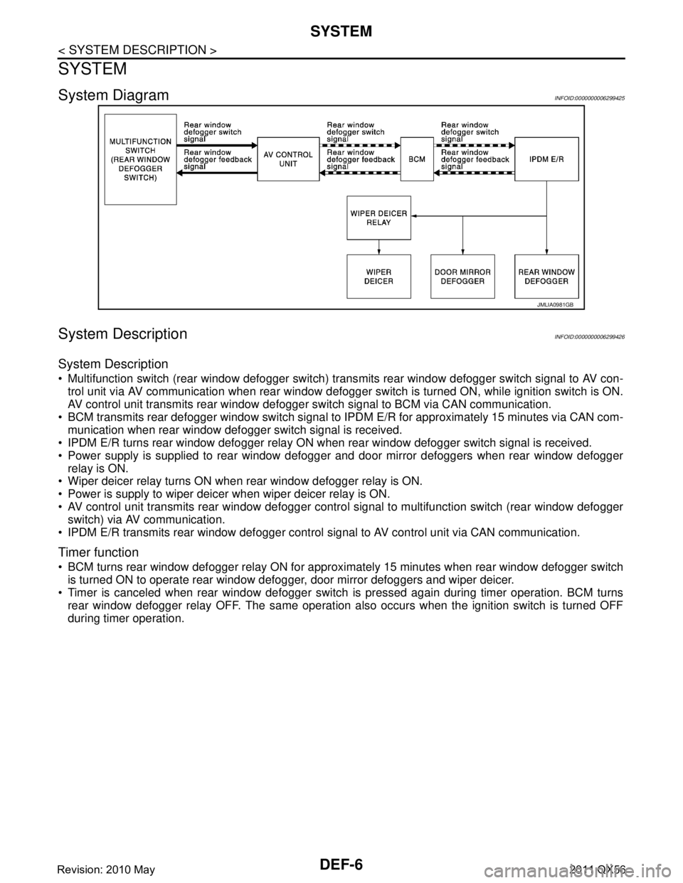
System DiagramINFOID:0000000006299425
System DescriptionINFOID:0000000006299426
System Description
Multifunction switch (rear window defogger switch) transmits rear window defogger switch signal to AV con-
trol unit via AV communication when rear window defogger switch is turned ON, while ignition switch is ON.
AV control unit transmits rear window defogger switch signal to BCM via CAN communication.
BCM transmits rear defogger window switch signal to IPDM E/R for approximately 15 minutes via CAN com-
munication when rear window defogger switch signal is received.
IPDM E/R turns rear window defogger relay ON when rear window defogger switch signal is received.
Power supply is supplied to rear window defogger and door mirror defoggers when rear window defogger
relay is ON.
Wiper deicer relay turns ON when rear window defogger relay is ON.
Power is supply to wiper deicer when wiper deicer relay is ON.
AV control unit transmits rear window defogger contro l signal to multifunction switch (rear window defogger
switch) via AV communication.
IPDM E/R transmits rear window defogger control signal to AV control unit via CAN communication.
Timer function
BCM turns rear window defogger relay ON for appr oximately 15 minutes when rear window defogger switch
is turned ON to operate rear window defogger, door mirror defoggers and wiper deicer.
Timer is canceled when rear window defogger switch is pressed again during timer operation. BCM turns
rear window defogger relay OFF. The same operation also occurs when the ignition switch is turned OFF
during timer operation.
JMLIA0981GB
Revision: 2010 May2011 QX56
Page 1499 of 5598

DIAGNOSIS SYSTEM (BCM)DEF-7
< SYSTEM DESCRIPTION >
C
DE
F
G H
I
J
K
M A
B
DEF
N
O P
DIAGNOSIS SYSTEM (BCM)
COMMON ITEM
COMMON ITEM : CONSULT-III Fu nction (BCM - COMMON ITEM)INFOID:0000000006349773
APPLICATION ITEM
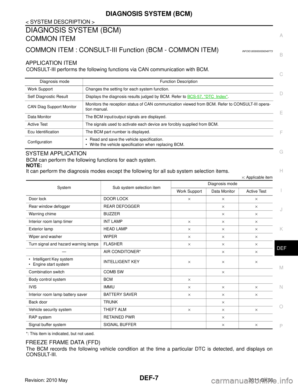
CONSULT-III performs the following functions via CAN communication with BCM.
SYSTEM APPLICATION
BCM can perform the following functions for each system.
NOTE:
It can perform the diagnosis modes except the following for all sub system selection items.
×: Applicable item
*: This item is indicated, but not used.
FREEZE FRAME DATA (FFD)
The BCM records the following vehicle condition at the time a particular DTC is detected, and displays on
CONSULT-III.
Diagnosis mode Function Description
Work Support Changes the setting for each system function.
Self Diagnostic Result Displays the diagnosis results judged by BCM. Refer to BCS-57, "
DTCIndex".
CAN Diag Support Monitor Monitors the reception status of CAN communication viewed from BCM. Refer to CONSULT-III opera-
tion manual.
Data Monitor The BCM input/output signals are displayed.
Active Test The signals used to activate each device are forcibly supplied from BCM.
Ecu Identification The BCM part number is displayed.
Configuration Read and save the vehicle specification.
Write the vehicle specification when replacing BCM.
System Sub system selection item Diagnosis mode
Work Support Data Monitor Active Test
Door lock DOOR LOCK ×××
Rear window defo gger REAR DEFOGGER ××
Warning chime BUZZER ××
Interior room lamp timer INT LAMP ×××
Exterior lamp HEAD LAMP ×××
Wiper and washer WIPER ×××
Turn signal and hazard warning lamps FLASHER ×××
— AIR CONDITONER* ××
Intelligent Key system
Engine start system INTELLIGENT KEY
×××
Combination switch COMB SW ×
Body control system BCM ×
IVIS IMMU ×××
Interior room lamp battery saver BATTERY SAVER ×××
Back door TRUNK ×
Vehicle security system THEFT ALM ×××
RAP system RETAINED PWR ×
Signal buffer system SIGNAL BUFFER ××
Revision: 2010 May2011 QX56
Page 1502 of 5598

DEF-10
< SYSTEM DESCRIPTION >
DIAGNOSIS SYSTEM (IPDM E/R)
DIAGNOSIS SYSTEM (IPDM E/R)
Diagnosis DescriptionINFOID:0000000006349776
AUTO ACTIVE TEST
Description
In auto active test, the IPDM E/R sends a drive signal to the following systems to check their operation.
Oil pressure warning lamp
Rear window defogger
Front wiper (LO, HI)
Parking lamp
License plate lamp
Tail lamp
Side marker lamp
Front fog lamp
Headlamp (LO, HI)
A/C compressor (magnet clutch)
Operation Procedure
CAUTION:
Never perform auto active test in the following conditions.
Engine is running.
CONSULT-III is connected.
1. Close the hood and lift the wiper arms from the windshield. (Prevent windshield damage due to wiper
operation)
NOTE:
When auto active test is performed with hood opened, sprinkle water on windshield beforehand.
2. Turn the ignition switch OFF.
3. Turn the ignition switch ON, and within 20 seconds, pr ess the driver door switch 10 times. Then turn the
ignition switch OFF.
CAUTION:
Close passenger door.
4. Turn the ignition switch ON within 10 seconds. Af ter that the horn sounds once and the auto active test
starts.
CAUTION:
Engine starts when igniti on switch is turned ON while brake pedal is depressed.
5. The oil pressure warning lamp starts blinking when the auto active test starts.
6. After a series of the following operations is repeated 3 times, auto active test is completed.
NOTE:
When auto active test has to be cancelled halfway through test, turn the ignition switch OFF.
When auto active test is not activated, door swit ch may be the cause. Check door switch. Refer to DLK-117,
"ComponentFunctionCheck".
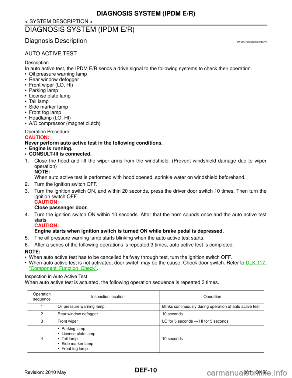
Inspection in Auto Active Test
When auto active test is actuated, the following operation sequence is repeated 3 times.
Operation
sequence Inspection location Operation
1 Oil pressure warning lamp Blinks continuously during operation of auto active test
2 Rear window defogger 10 seconds
3 Front wiper LO for 5 seconds → HI for 5 seconds
4 Parking lamp
License plate lamp
Tail lamp
Side marker lamp
Front fog lamp 10 seconds
Revision: 2010 May2011 QX56