2011 INFINITI QX56 lock
[x] Cancel search: lockPage 2631 of 5598
TIMING CHAINEM-69
< REMOVAL AND INSTALLATION >
C
DE
F
G H
I
J
K L
M A
EM
NP
O
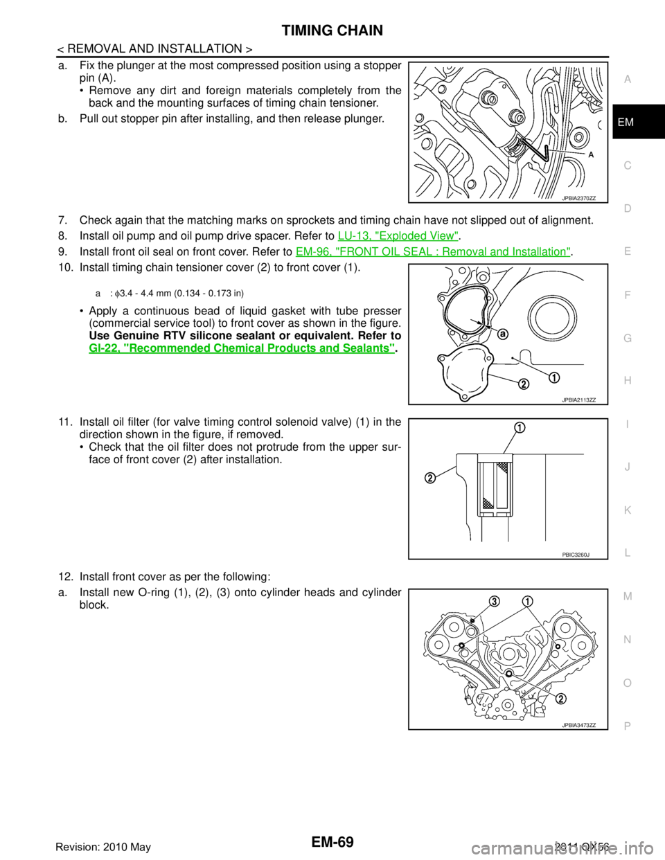
a. Fix the plunger at the most compressed position using a stopper
pin (A).
Remove any dirt and foreign materials completely from theback and the mounting surfaces of timing chain tensioner.
b. Pull out stopper pin after installing, and then release plunger.
7. Check again that the matching marks on sprockets and timing chain have not slipped out of alignment.
8. Install oil pump and oil pump drive spacer. Refer to LU-13, "
Exploded View".
9. Install front oil seal on front cover. Refer to EM-96, "
FRONT OIL SEAL : Removal and Installation".
10. Install timing chain tensioner cover (2) to front cover (1).
Apply a continuous bead of liquid gasket with tube presser(commercial service tool) to front cover as shown in the figure.
Use Genuine RTV silicone seal ant or equivalent. Refer to
GI-22, "
Recommended Chemical Products and Sealants".
11. Install oil filter (for valve timing control solenoid valve) (1) in the direction shown in the figure, if removed.
Check that the oil filter does not protrude from the upper sur-
face of front cover (2) after installation.
12. Install front cover as per the following:
a. Install new O-ring (1), (2), (3) onto cylinder heads and cylinder block.
JPBIA2370ZZ
a: φ3.4 - 4.4 mm (0.134 - 0.173 in)
JPBIA2113ZZ
PBIC3260J
JPBIA3473ZZ
Revision: 2010 May2011 QX56
Page 2632 of 5598
EM-70
< REMOVAL AND INSTALLATION >
TIMING CHAIN
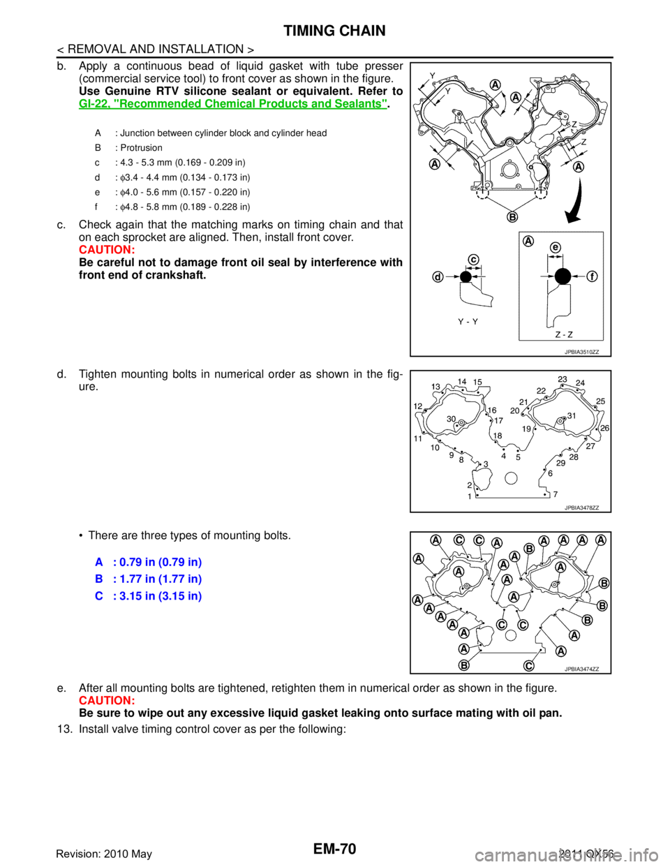
b. Apply a continuous bead of liquid gasket with tube presser(commercial service tool) to front cover as shown in the figure.
Use Genuine RTV silicone seal ant or equivalent. Refer to
GI-22, "
Recommended Chemical Products and Sealants".
c. Check again that the matching marks on timing chain and that on each sprocket are aligned. Then, install front cover.
CAUTION:
Be careful not to damage front oil seal by interference with
front end of crankshaft.
d. Tighten mounting bolts in numerical order as shown in the fig- ure.
There are three types of mounting bolts.
e. After all mounting bolts are tightened, retighten t hem in numerical order as shown in the figure.
CAUTION:
Be sure to wipe out any excessive liquid gasket leaking onto surface mating with oil pan.
13. Install valve timing control cover as per the following:
A : Junction between cylinder block and cylinder head
B : Protrusion
c : 4.3 - 5.3 mm (0.169 - 0.209 in)
d: φ3.4 - 4.4 mm (0.134 - 0.173 in)
e: φ4.0 - 5.6 mm (0.157 - 0.220 in)
f: φ4.8 - 5.8 mm (0.189 - 0.228 in)
JPBIA3510ZZ
JPBIA3478ZZ
A : 0.79 in (0.79 in)
B : 1.77 in (1.77 in)
C : 3.15 in (3.15 in)
JPBIA3474ZZ
Revision: 2010 May2011 QX56
Page 2634 of 5598
EM-72
< REMOVAL AND INSTALLATION >
TIMING CHAIN
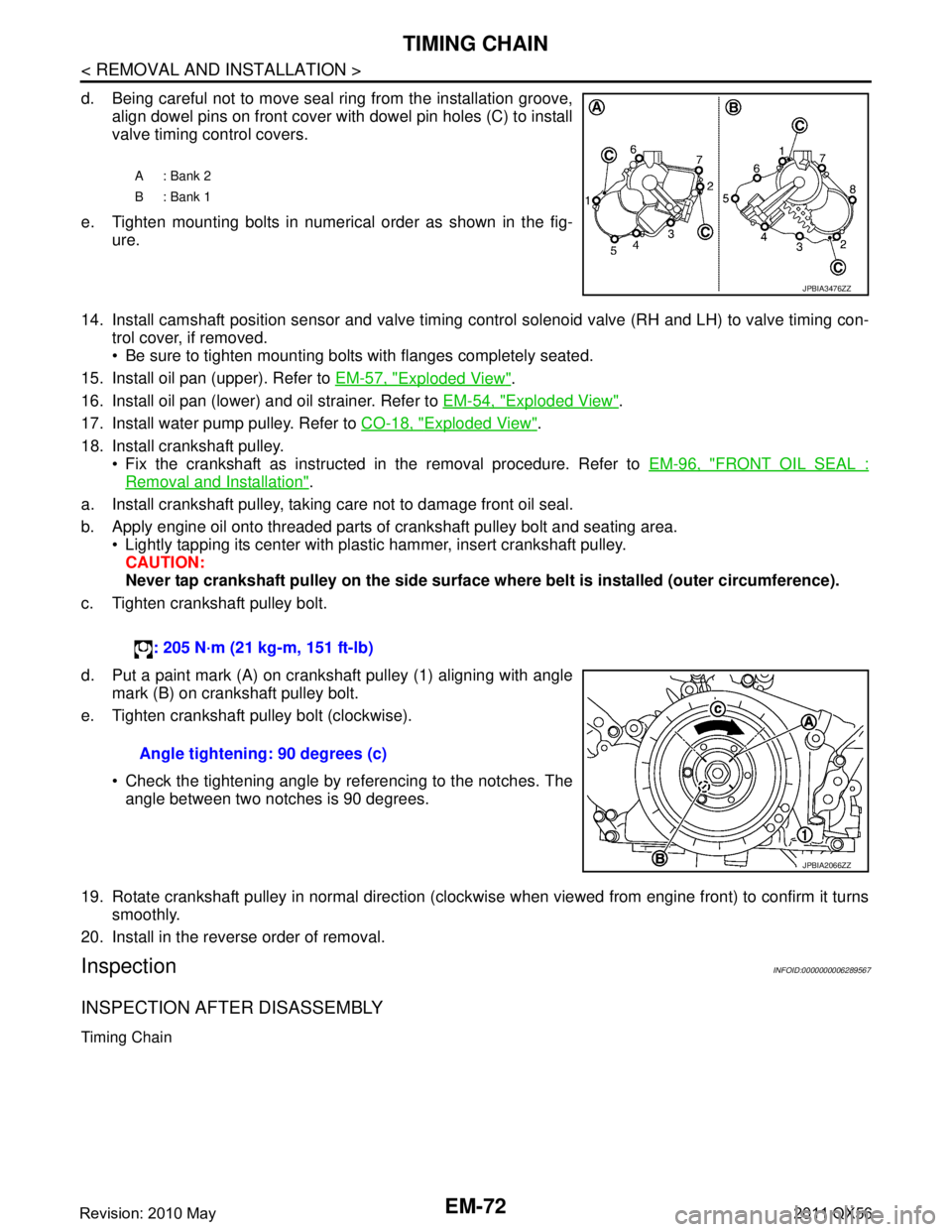
d. Being careful not to move seal ring from the installation groove,align dowel pins on front cover with dowel pin holes (C) to install
valve timing control covers.
e. Tighten mounting bolts in numerical order as shown in the fig- ure.
14. Install camshaft position sensor and valve timing c ontrol solenoid valve (RH and LH) to valve timing con-
trol cover, if removed.
Be sure to tighten mounting bolts with flanges completely seated.
15. Install oil pan (upper). Refer to EM-57, "
Exploded View".
16. Install oil pan (lower) and oil strainer. Refer to EM-54, "
Exploded View".
17. Install water pump pulley. Refer to CO-18, "
Exploded View".
18. Install crankshaft pulley. Fix the crankshaft as instructed in the removal procedure. Refer to EM-96, "
FRONT OIL SEAL :
Removal and Installation".
a. Install crankshaft pulley, taking care not to damage front oil seal.
b. Apply engine oil onto threaded parts of crankshaft pulley bolt and seating area. Lightly tapping its center with plastic hammer, insert crankshaft pulley.
CAUTION:
Never tap crankshaft pulley on the side surface wh ere belt is installed (outer circumference).
c. Tighten crankshaft pulley bolt.
d. Put a paint mark (A) on crankshaft pulley (1) aligning with angle mark (B) on crankshaft pulley bolt.
e. Tighten crankshaft pulley bolt (clockwise).
Check the tightening angle by referencing to the notches. Theangle between two notches is 90 degrees.
19. Rotate crankshaft pulley in normal direction (clockwise when viewed from engine front) to confirm it turns smoothly.
20. Install in the reverse order of removal.
InspectionINFOID:0000000006289567
INSPECTION AFTER DISASSEMBLY
Timing Chain
A: Bank 2
B: Bank 1
JPBIA3476ZZ
: 205 N·m (21 kg-m, 151 ft-lb)
Angle tightening: 90 degrees (c)
JPBIA2066ZZ
Revision: 2010 May2011 QX56
Page 2641 of 5598

CAMSHAFTEM-79
< REMOVAL AND INSTALLATION >
C
DE
F
G H
I
J
K L
M A
EM
NP
O
1. Put V-block on precise flat table, and support No. 2 and 5 jour-
nals of camshaft.
CAUTION:
Never support No. 1 journal (on the side of camshaft
sprocket) because it has a different diameter from the other
four locations.
2. Set a dial indicator vertically to No. 3 journal.
3. Turn exhaust camshaft to one direction with hands, and mea- sure the camshaft runout on a dial indicator. (Total indicator
reading)
4. If it exceeds the limit, replace exhaust camshaft.
Exhaust Camshaft Cam Height
Measure the exhaust camshaft cam height with a micrometer.
If wear exceeds the limit, replace exhaust camshaft.
Exhaust Camshaft Journal Oil Clearance
EXHAUST CAMSHAFT JOURNAL DIAMETER
Measure the outer diameter of exhaust camshaft journal with a micrometer (A).
VVEL LADDER ASSEMBLY (EXH SIDE) INNER DIAMETER Tighten VVEL ladder assembly bolts to the specifi ed torque. Refer to “ASSEMBLY” for the tightening proce-
dure.
Measure inner diameter (A) of VVEL ladder assembly (exhaust side) with a bore gauge.
EXHAUST CAMSHAFT JOURNAL OIL CLEARANCE
Standard and limit
: Refer to EM-133, "
Camshaft".
PBIC0929E
Standard and limit
: Refer to EM-133, "
Camshaft".
EMQ0072D
Standard : Refer to EM-133, "Camshaft".
JPBIA0122ZZ
Standard : Refer to EM-133, "Camshaft".
PBIC1645E
Revision: 2010 May2011 QX56
Page 2642 of 5598
![INFINITI QX56 2011 Factory Service Manual
EM-80
< REMOVAL AND INSTALLATION >
CAMSHAFT
(Oil clearance) = [VVEL ladder assembly (exhaust side) inner diameter] – [Exhaust camshaft journal diame-
ter].
If the calculated value exceeds the l INFINITI QX56 2011 Factory Service Manual
EM-80
< REMOVAL AND INSTALLATION >
CAMSHAFT
(Oil clearance) = [VVEL ladder assembly (exhaust side) inner diameter] – [Exhaust camshaft journal diame-
ter].
If the calculated value exceeds the l](/manual-img/42/57033/w960_57033-2641.png)
EM-80
< REMOVAL AND INSTALLATION >
CAMSHAFT
(Oil clearance) = [VVEL ladder assembly (exhaust side) inner diameter] – [Exhaust camshaft journal diame-
ter].
If the calculated value exceeds the limit, replace either or both exhaust camshaft and VVEL ladder assembly
& cylinder head assembly.
NOTE:
VVEL ladder assembly cannot be replaced as a singl e part, because it is machined together with cylinder
head assembly.
Exhaust Camshaft End Play
Install a dial indicator in thrust direction on front end of camshaft. Measure the end play of a dial indicator when exhaust camshaft is
moved forward/backward (in direction of axis).
Measure the following parts if out of the limit.
- Dimension “A” for exhaust camshaft No. 1 journal
- Dimension “B” for cylinder head No. 1 journal bearing
Refer to the standards above, and then replace exhaust camshaft
and/or VVEL ladder assembly & cylinder head assembly.
NOTE:
Cylinder head assembly cannot be replaced as a single part,
because it is machined together with VVEL ladder assembly.
Exhaust Camshaft Sprocket Runout
1. Put V-block on precise flat table, and support No. 2 and 5 journals of exhaust camshaft.
CAUTION:
Never support No. 1 journal (on the side of cam shaft sprocket) because it has a different diameter
from the other four locations.
2. Measure the exhaust camshaft sprocket runout with a dial indi- cator. (Total indicator reading)
3. If it exceeds the limit, replace exhaust camshaft sprocket.
Valve Lifter (EXH)
Standard and limit : Refer to EM-133, "Camshaft".
Standard and limit : Refer to EM-133, "
Camshaft".
SEM864E
Standard : 30.500 - 30.548 mm (1.2008 - 1.2027 in)
Standard : 30.360 - 30.385 mm (1.1953 - 1.1963 in)
JPBIA3516ZZ
Limit : Refer to EM-133, "Camshaft".
PBIC0930E
Revision: 2010 May2011 QX56
Page 2644 of 5598
EM-82
< REMOVAL AND INSTALLATION >
CAMSHAFT
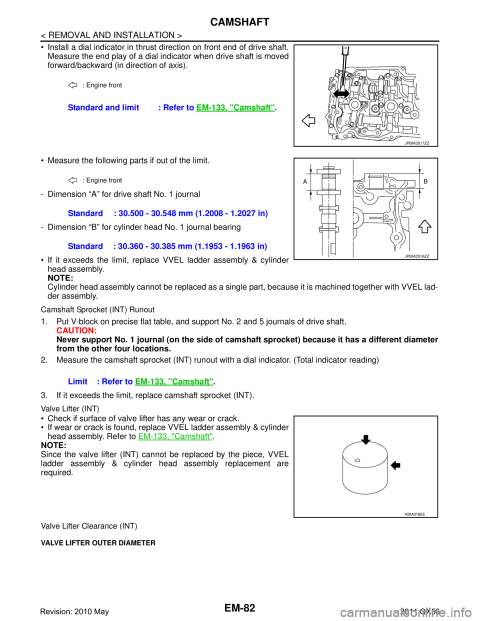
Install a dial indicator in thrust direction on front end of drive shaft.Measure the end play of a dial indicator when drive shaft is moved
forward/backward (in direction of axis).
Measure the following parts if out of the limit.
- Dimension “A” for drive shaft No. 1 journal
- Dimension “B” for cylinder head No. 1 journal bearing
If it exceeds the limit, replace VVEL ladder assembly & cylinder head assembly.
NOTE:
Cylinder head assembly cannot be replaced as a single part, because it is machined together with VVEL lad-
der assembly.
Camshaft Sprocket (INT) Runout
1. Put V-block on precise flat table, and support No. 2 and 5 journals of drive shaft. CAUTION:
Never support No. 1 journal (on the side of cam shaft sprocket) because it has a different diameter
from the other four locations.
2. Measure the camshaft sprocket (INT) runout with a dial indicator. (Total indicator reading)
3. If it exceeds the limit, r eplace camshaft sprocket (INT).
Valve Lifter (INT)
Check if surface of valve li fter has any wear or crack.
If wear or crack is found, replace VVEL ladder assembly & cylinder
head assembly. Refer to EM-133, "
Camshaft".
NOTE:
Since the valve lifter (INT) cannot be replaced by the piece, VVEL
ladder assembly & cylinder head assembly replacement are
required.
Valve Lifter Clearance (INT)
VALVE LIFTER OUTER DIAMETER
: Engine front
Standard and limit : Refer to EM-133, "Camshaft".
JPBIA3517ZZ
: Engine front
Standard : 30.500 - 30.548 mm (1.2008 - 1.2027 in)
Standard : 30.360 - 30.385 mm (1.1953 - 1.1963 in)
JPBIA3516ZZ
Limit : Refer to EM-133, "Camshaft".
KBIA0182E
Revision: 2010 May2011 QX56
Page 2648 of 5598
EM-86
< REMOVAL AND INSTALLATION >
CYLINDER HEAD
CYLINDER HEAD
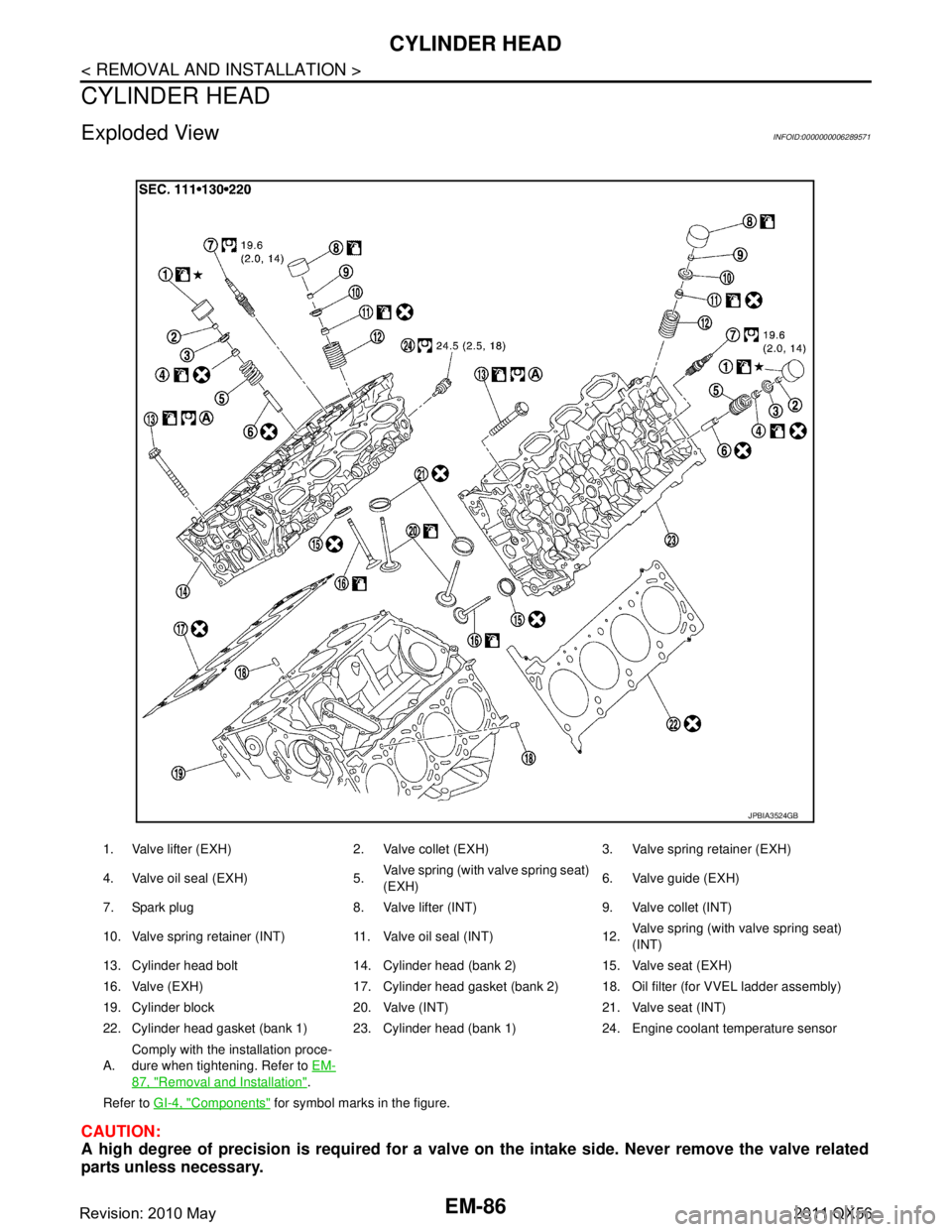
Exploded ViewINFOID:0000000006289571
CAUTION:
A high degree of precision is required for a valve on the intake side. Never remove the valve related
parts unless necessary.
1. Valve lifter (EXH) 2. Valve collet (EXH) 3. Valve spring retainer (EXH)
4. Valve oil seal (EXH) 5. Valve spring (with valve spring seat)
(EXH)6. Valve guide (EXH)
7. Spark plug 8. Valve lifter (INT) 9. Valve collet (INT)
10. Valve spring retainer (INT) 11. Valve oil seal (INT) 12. Valve spring (with valve spring seat)
(INT)
13. Cylinder head bolt 14. Cylinder head (bank 2) 15. Valve seat (EXH)
16. Valve (EXH) 17. Cylinder head gasket (bank 2) 18. Oil filter (for VVEL ladder assembly)
19. Cylinder block 20. Valve (INT) 21. Valve seat (INT)
22. Cylinder head gasket (bank 1) 23. Cylinder head (bank 1) 24. Engine coolant temperature sensor
A. Comply with the installation proce-
dure when tightening. Refer to
EM-
87, "Removal and Installation".
Refer to GI-4, "
Components" for symbol marks in the figure.
JPBIA3524GB
Revision: 2010 May2011 QX56
Page 2649 of 5598
CYLINDER HEADEM-87
< REMOVAL AND INSTALLATION >
C
DE
F
G H
I
J
K L
M A
EM
NP
O
NOTE:
As for replacement of parts on the intake side as
shown in the exploded view, replace VVEL ladder assem-
bly & cylinder head assembly. (Only valve oil seals are replaceable as a single part.)
VVEL ladder assembly cannot be replaced as a singl e part, because it is machined together with cylinder
head assembly.
Removal and InstallationINFOID:0000000006289572
REMOVAL
1. Remove the following parts: Rocker cover and spark plug: Refer to EM-33, "
Exploded View".
Intake manifold: Refer to EM-30, "
Exploded View".
Exhaust manifold: Refer to EM-40, "
Exploded View".
Water inlet and thermostat housing: Refer to CO-20, "
Exploded View".
Water pipe and heater pipe: Refer to CO-20, "
Exploded View".
Timing chain: Refer to EM-61, "
Exploded View".
Camshaft (EXH) and VVEL ladder assembly: Refer to EM-74, "
Exploded View".
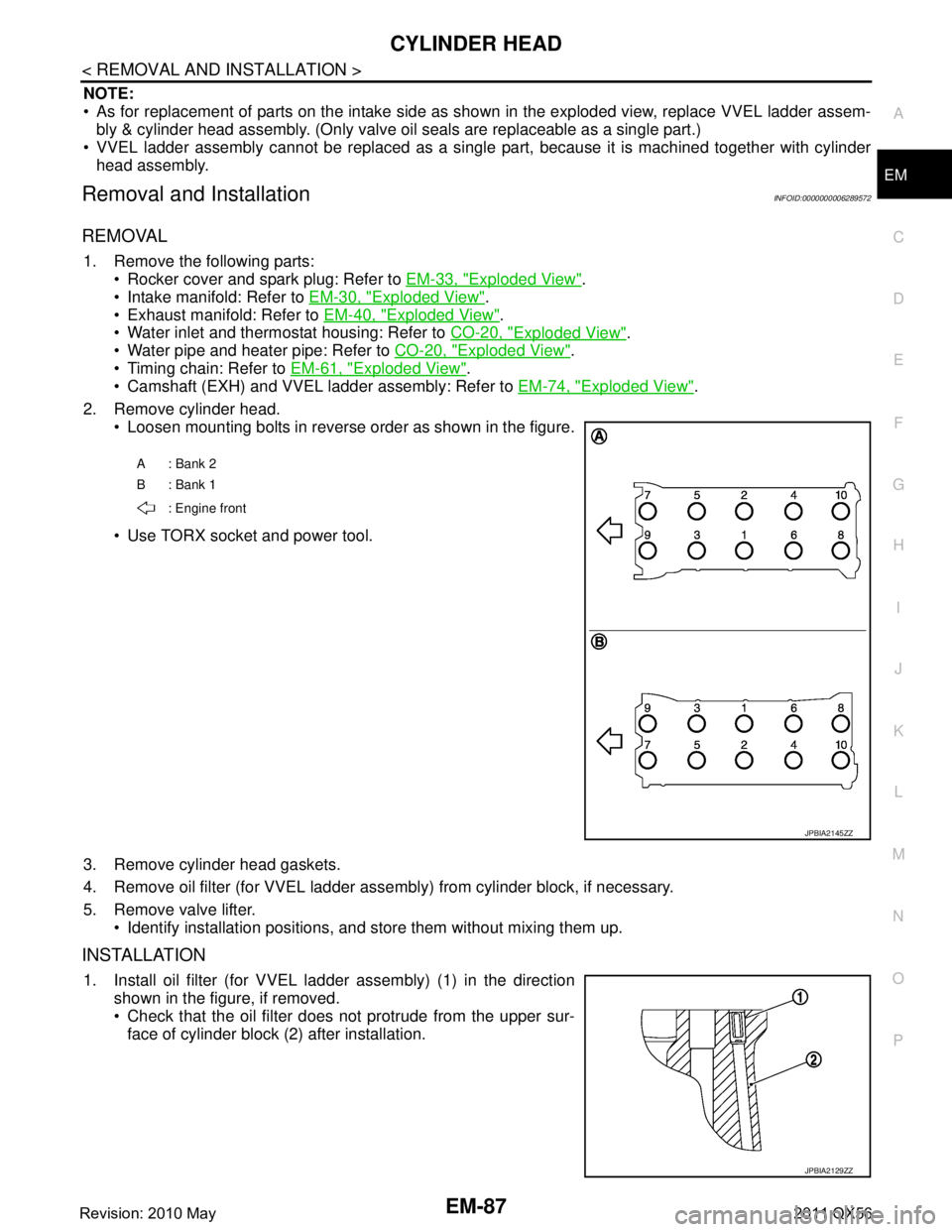
2. Remove cylinder head. Loosen mounting bolts in reverse order as shown in the figure.
Use TORX socket and power tool.
3. Remove cylinder head gaskets.
4. Remove oil filter (for VVEL ladder asse mbly) from cylinder block, if necessary.
5. Remove valve lifter. Identify installation positions, and store them without mixing them up.
INSTALLATION
1. Install oil filter (for VVEL l adder assembly) (1) in the direction
shown in the figure, if removed.
Check that the oil filter does not protrude from the upper sur-
face of cylinder block (2) after installation.
A: Bank 2
B: Bank 1
: Engine front
JPBIA2145ZZ
JPBIA2129ZZ
Revision: 2010 May2011 QX56