Page 2650 of 5598
EM-88
< REMOVAL AND INSTALLATION >
CYLINDER HEAD
2. Install new cylinder head gaskets.
3. Install cylinder head as per the following: CAUTION:
If cylinder head bolts are re-used, check their ou ter diameters before installation. Refer to EM-92,
"Inspection".
Before installing cylinder head, inspect cylinder head distortion. Refer to EM-92, "
Inspection".
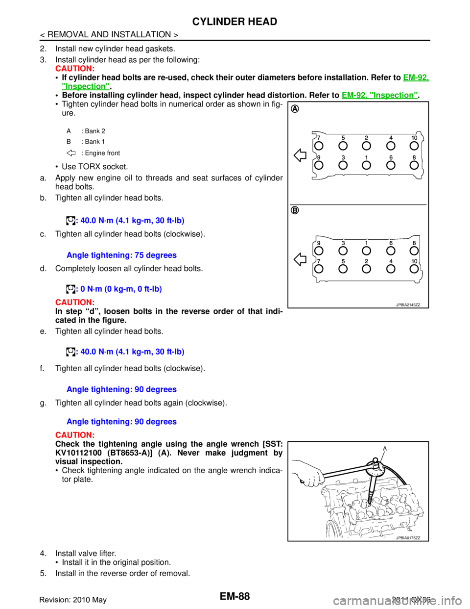
Tighten cylinder head bolts in numerical order as shown in fig- ure.
Use TORX socket.
a. Apply new engine oil to threads and seat surfaces of cylinder head bolts.
b. Tighten all cylinder head bolts.
c. Tighten all cylinder head bolts (clockwise).
d. Completely loosen all cylinder head bolts.
CAUTION:
In step “d”, loosen bolts in the reverse order of that indi-
cated in the figure.
e. Tighten all cylinder head bolts.
f. Tighten all cylinder head bolts (clockwise).
g. Tighten all cylinder head bolts again (clockwise).
CAUTION:
Check the tightening angle us ing the angle wrench [SST:
KV10112100 (BT8653-A)] (A). Never make judgment by
visual inspection.
Check tightening angle indicated on the angle wrench indica- tor plate.
4. Install valve lifter. Install it in the original position.
5. Install in the reverse order of removal.
A: Bank 2
B: Bank 1
: Engine front
: 40.0 N·m (4.1 kg-m, 30 ft-lb)
Angle tightening: 75 degrees : 0 N·m (0 kg-m, 0 ft-lb)
: 40.0 N·m (4.1 kg-m, 30 ft-lb)
JPBIA2145ZZ
Angle tightening: 90 degrees
Angle tightening: 90 degrees
JPBIA0175ZZ
Revision: 2010 May2011 QX56
Page 2655 of 5598
CYLINDER HEADEM-93
< REMOVAL AND INSTALLATION >
C
DE
F
G H
I
J
K L
M A
EM
NP
O
Cylinder Head Distortion
NOTE:
When performing this inspection, cylinder block distortion should be also checked. Refer to
EM-115, "
Inspec-
tion".
1. Using a scraper, wipe out oil, scale, gasket, s ealant and carbon deposits from surface of cylinder head.
CAUTION:
Never allow gasket fragments to enter engine oil or engine coolant passages.
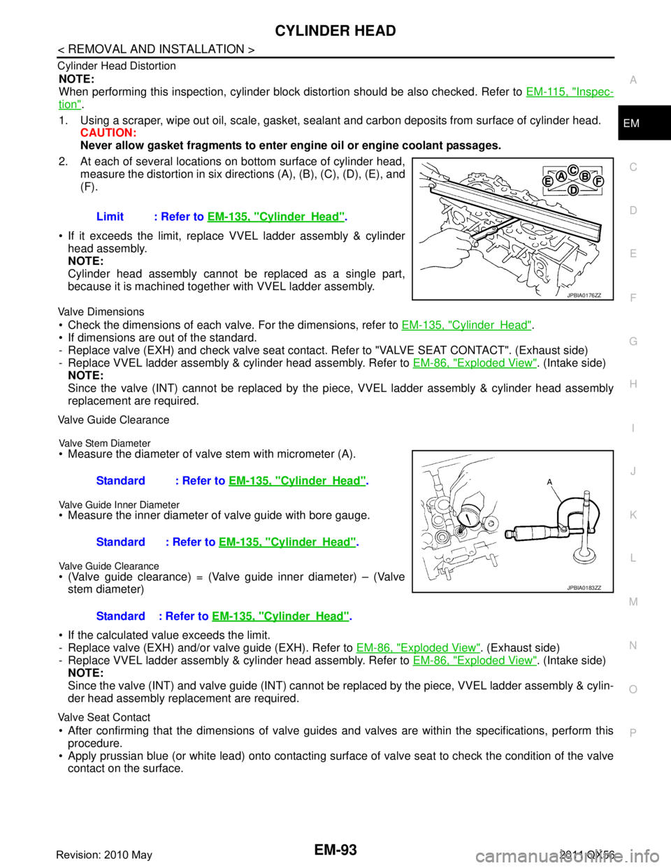
2. At each of several locations on bottom surface of cylinder head, measure the distortion in six directi ons (A), (B), (C), (D), (E), and
(F).
If it exceeds the limit, replace VVEL ladder assembly & cylinder head assembly.
NOTE:
Cylinder head assembly cannot be replaced as a single part,
because it is machined together with VVEL ladder assembly.
Valve Dimensions
Check the dimensions of each valv e. For the dimensions, refer to EM-135, "CylinderHead".
If dimensions are out of the standard.
- Replace valve (EXH) and check valve seat contact. Refer to "VALVE SEAT CONTACT". (Exhaust side)
- Replace VVEL ladder assembly & cylinder head assembly. Refer to EM-86, "
Exploded View". (Intake side)
NOTE:
Since the valve (INT) cannot be replaced by the pi ece, VVEL ladder assembly & cylinder head assembly
replacement are required.
Valve Guide Clearance
Valve Stem Diameter
Measure the diameter of valve stem with micrometer (A).
Valve Guide Inner Diameter
Measure the inner diameter of valve guide with bore gauge.
Valve Guide Clearance
(Valve guide clearance) = (Valve guide inner diameter) – (Valve
stem diameter)
If the calculated value exceeds the limit.
- Replace valve (EXH) and/or valve guide (EXH). Refer to EM-86, "
Exploded View". (Exhaust side)
- Replace VVEL ladder assembly & cylinder head assembly. Refer to EM-86, "
Exploded View". (Intake side)
NOTE:
Since the valve (INT) and valve guide (INT) cannot be repl aced by the piece, VVEL ladder assembly & cylin-
der head assembly replacement are required.
Valve Seat Contact
After confirming that the dimensions of valve guides and valves are within the specifications, perform this
procedure.
Apply prussian blue (or white lead) onto contacting surfac e of valve seat to check the condition of the valve
contact on the surface. Limit : Refer to
EM-135, "
CylinderHead".
JPBIA0176ZZ
Standard : Refer to EM-135, "CylinderHead".
Standard : Refer to EM-135, "
CylinderHead".
Standard : Refer to EM-135, "
CylinderHead".
JPBIA0183ZZ
Revision: 2010 May2011 QX56
Page 2659 of 5598
OIL SEALEM-97
< REMOVAL AND INSTALLATION >
C
DE
F
G H
I
J
K L
M A
EM
NP
O
REAR OIL SEAL : Removal and InstallationINFOID:0000000006289575
REMOVAL
1. Remove transmission assembly. Refer to
TM-205, "2WD : Exploded View" (2WD models) or TM-208,
"4WD : Exploded View" (4WD models).
2. Remove drive plate. Refer to EM-106, "
Exploded View".
3. Remove rear oil seal with a suitable tool. CAUTION:
Be careful not to damage crankshaft and cylinder block.
INSTALLATION
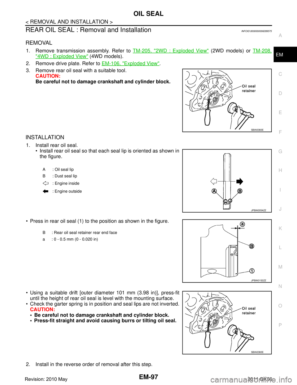
1. Install rear oil seal. Install rear oil seal so that each seal lip is oriented as shown in
the figure.
Press in rear oil seal (1) to the position as shown in the figure.
Using a suitable drift [outer diameter 101 mm (3.98 in)], press-fit until the height of rear oil seal is level with the mounting surface.
Check the garter spring is in position and seal lips are not inverted. CAUTION:
Be careful not to damage crankshaft and cylinder block.
Press-fit straight and avoid cau sing burrs or tilting oil seal.
2. Install in the reverse order of removal after this step.
SBIA0360E
A : Oil seal lip
B : Dust seal lip : Engine inside
: Engine outside
JPBIA0054ZZ
B : Rear oil seal retainer rear end face
a : 0 - 0.5 mm (0 - 0.020 in)
JPBIA0152ZZ
SBIA0360E
Revision: 2010 May2011 QX56
Page 2666 of 5598
EM-104
< UNIT DISASSEMBLY AND ASSEMBLY >
ENGINE STAND SETTING
7. Drain engine coolant by removing water drain plug (3) from bothsides of the cylinder block as shown in the figure.
1: Washer
2 : Plug (engine coolant)
4 : Plug (engine oil)
5: Washer
: Engine front
Refer to GI-4, "
Components" for symbol marks in the figure.
Water drain plug torque
: 19.6 N·m (2.0 kg/m, 14 ft-lb)
JPBIA3501ZZ
Revision: 2010 May2011 QX56
Page 2668 of 5598
EM-106
< UNIT DISASSEMBLY AND ASSEMBLY >
CYLINDER BLOCK
CYLINDER BLOCK
Exploded ViewINFOID:0000000006289582
1. Knock sensor 2. Cylinder block 3. Side bolt
4. Thrust bearing 5. Main bearing (upper) 6. Crankshaft key
7. Crankshaft 8. Main bearing (lower) 9. Main bearing cap
JPBIA4511GB
Revision: 2010 May2011 QX56
Page 2669 of 5598
CYLINDER BLOCKEM-107
< UNIT DISASSEMBLY AND ASSEMBLY >
C
DE
F
G H
I
J
K L
M A
EM
NP
O
Disassembly and AssemblyINFOID:0000000006289583
DISASSEMBLY
1. Remove the following parts:
Oil pans (lower and upper): Refer to EM-54, "
Exploded View" and EM-57, "Exploded View".
Front cover and timing chain: Refer to EM-61, "
Exploded View".
Cylinder head: Refer to EM-86, "
Exploded View".
2. Remove knock sensor. CAUTION:
Carefully handle knock sensor avoiding shocks.
3. Remove oil filter (for VVEL ladder assembly ) from cylinder block, if necessary. Refer to EM-86, "
Exploded
View".
4. Remove piston and connecting rod assembly as per the following: Before removing piston and connecting rod assembly, check the connecting rod side clearance. Refer to
EM-115, "
Inspection".
CAUTION:
Be careful not to drop connecting r od bearing, and to scratch the surface.
a. Position crankshaft pin corresponding to connecting rod to be removed onto the bottom dead center.
b. Loosen mounting bolts, and remove connecting rod bearing cap.
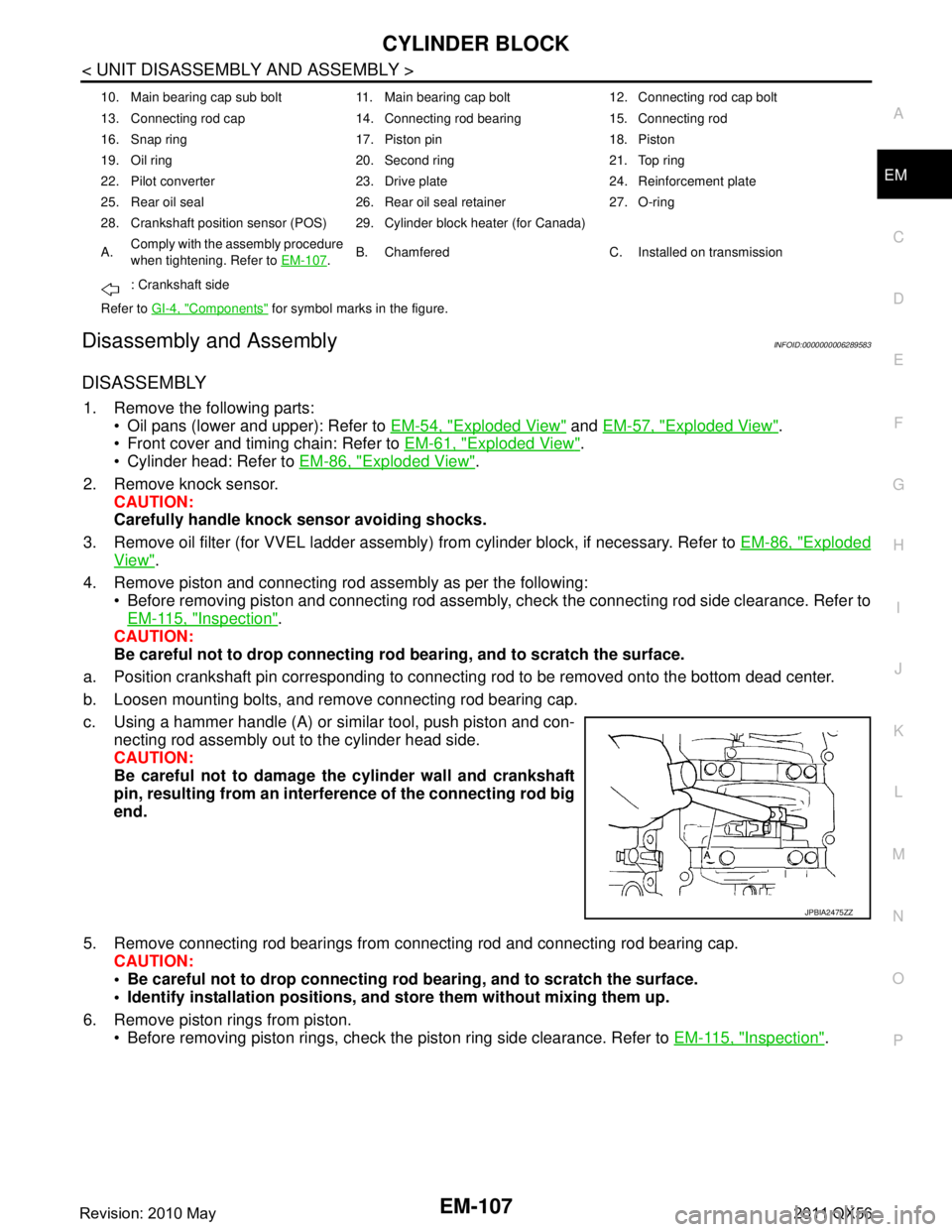
c. Using a hammer handle (A) or similar tool, push piston and con- necting rod assembly out to the cylinder head side.
CAUTION:
Be careful not to damage the cylinder wall and crankshaft
pin, resulting from an interf erence of the connecting rod big
end.
5. Remove connecting rod bearings from connecting rod and connecting rod bearing cap.
CAUTION:
Be careful not to drop connecting rod bearing, and to scratch the surface.
Identify installation positions, and store them without mixing them up.
6. Remove piston rings from piston. Before removing piston rings, check the piston ring side clearance. Refer to EM-115, "
Inspection".
10. Main bearing cap sub bolt 11. Main bearing cap bolt 12. Connecting rod cap bolt
13. Connecting rod cap 14. Connecting rod bearing 15. Connecting rod
16. Snap ring 17. Piston pin 18. Piston
19. Oil ring 20. Second ring 21. Top ring
22. Pilot converter 23. Drive plate 24. Reinforcement plate
25. Rear oil seal 26. Rear oil seal retainer 27. O-ring
28. Crankshaft position sensor (POS) 29. Cylinder block heater (for Canada)
A.Comply with the assembly procedure
when tightening. Refer to
EM-107
.B. Chamfered C. Installed on transmission
: Crankshaft side
Refer to GI-4, "
Components" for symbol marks in the figure.
JPBIA2475ZZ
Revision: 2010 May2011 QX56
Page 2670 of 5598
EM-108
< UNIT DISASSEMBLY AND ASSEMBLY >
CYLINDER BLOCK
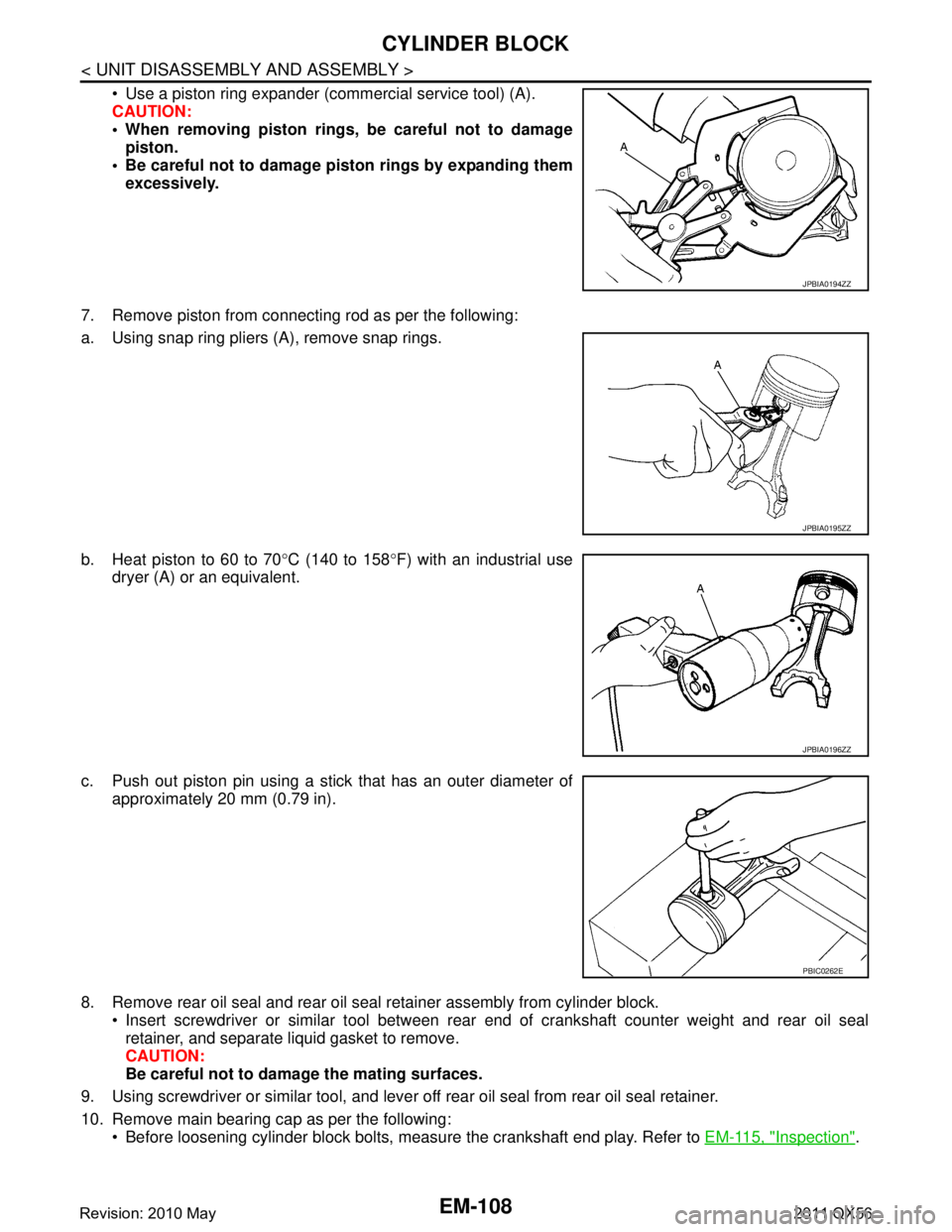
Use a piston ring expander (commercial service tool) (A).
CAUTION:
When removing piston rings, be careful not to damagepiston.
Be careful not to damage piston rings by expanding them
excessively.
7. Remove piston from connecting rod as per the following:
a. Using snap ring pliers (A), remove snap rings.
b. Heat piston to 60 to 70 °C (140 to 158 °F) with an industrial use
dryer (A) or an equivalent.
c. Push out piston pin using a stick that has an outer diameter of approximately 20 mm (0.79 in).
8. Remove rear oil seal and rear oil seal retainer assembly from cylinder block. Insert screwdriver or similar tool between rear end of crankshaft counter weight and rear oil sealretainer, and separate liquid gasket to remove.
CAUTION:
Be careful not to damage the mating surfaces.
9. Using screwdriver or similar tool, and lever off rear oil seal from rear oil seal retainer.
10. Remove main bearing cap as per the following: Before loosening cylinder block bolts, measure the crankshaft end play. Refer to EM-115, "
Inspection".
JPBIA0194ZZ
JPBIA0195ZZ
JPBIA0196ZZ
PBIC0262E
Revision: 2010 May2011 QX56
Page 2671 of 5598
CYLINDER BLOCKEM-109
< UNIT DISASSEMBLY AND ASSEMBLY >
C
DE
F
G H
I
J
K L
M A
EM
NP
O
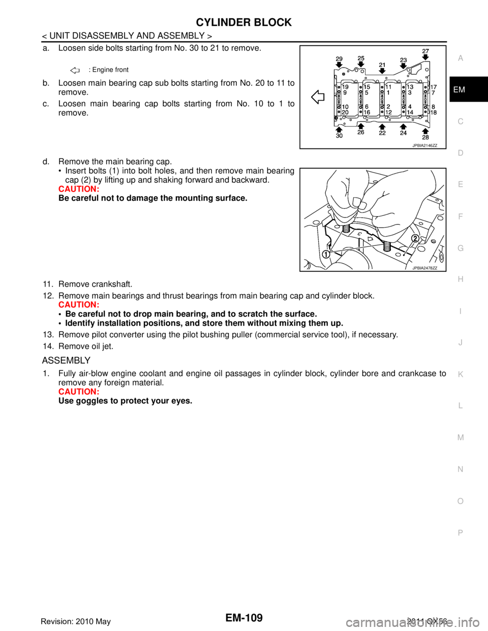
a. Loosen side bolts starting from No. 30 to 21 to remove.
b. Loosen main bearing cap sub bolts starting from No. 20 to 11 to
remove.
c. Loosen main bearing cap bolts starting from No. 10 to 1 to remove.
d. Remove the main bearing cap. Insert bolts (1) into bolt holes, and then remove main bearing
cap (2) by lifting up and shaking forward and backward.
CAUTION:
Be careful not to damage the mounting surface.
11. Remove crankshaft.
12. Remove main bearings and thrust bearings from main bearing cap and cylinder block. CAUTION:
Be careful not to drop main bear ing, and to scratch the surface.
Identify installation positions, and store them without mixing them up.
13. Remove pilot converter using the pilot bushing puller (commercial service tool), if necessary.
14. Remove oil jet.
ASSEMBLY
1. Fully air-blow engine coolant and engine oil passages in cylinder block, cylinder bore and crankcase to remove any foreign material.
CAUTION:
Use goggles to protect your eyes.
: Engine front
JPBIA2146ZZ
JPBIA2478ZZ
Revision: 2010 May2011 QX56