Page 2583 of 5598
DRIVE BELTSEM-21
< PERIODIC MAINTENANCE >
C
DE
F
G H
I
J
K L
M A
EM
NP
O
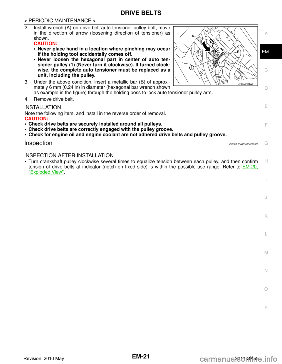
2. Install wrench (A) on drive belt auto tensioner pulley bolt, move
in the direction of arrow (loosening direction of tensioner) as
shown.
CAUTION:
Never place hand in a location where pinching may occurif the holding tool accidentally comes off.
Never loosen the hexagonal part in center of auto ten- sioner pulley (1) (Never turn it clockwise). If turned clock-
wise, the complete auto tensioner must be replaced as a
unit, including the pulley.
3. Under the above condition, insert a metallic bar (B) of approxi- mately 6 mm (0.24 in) in diameter (hexagonal bar wrench shown
as example in the figure) through the holding boss to lock auto tensioner pulley arm.
4. Remove drive belt.
INSTALLATION
Note the following item, and install in the reverse order of removal.
CAUTION:
Check drive belts are securely installed around all pulleys.
Check drive belts are correctly engaged with the pulley groove.
Check for engine oil and engine coolant ar e not adhered drive belts and pulley groove.
InspectionINFOID:0000000006289528
INSPECTION AFTER INSTALLATION
Turn crankshaft pulley clockwise several times to equalize tension between each pulley, and then confirm
tension of drive belts at indicator (notch on fixed side) is within the possible use range. Refer to EM-20,
"Exploded View".
JPBIA3484ZZ
Revision: 2010 May2011 QX56
Page 2588 of 5598
EM-26
< REMOVAL AND INSTALLATION >
DRIVE BELT AUTO TENSIONER AND IDLER PULLEY
DRIVE BELT AUTO TENSI ONER AND IDLER PULLEY
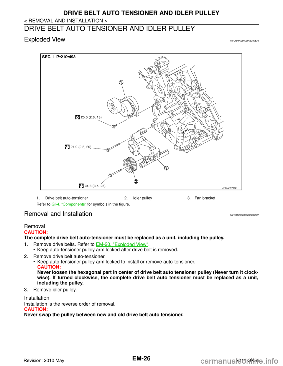
Exploded ViewINFOID:0000000006289536
Removal and InstallationINFOID:0000000006289537
Removal
CAUTION:
The complete drive belt auto-tensioner must be replaced as a unit, including the pulley.
1. Remove drive belts. Refer to EM-20, "
Exploded View".
Keep auto-tensioner pulley arm locked after drive belt is removed.
2. Remove drive belt auto-tensioner. Keep auto-tensioner pulley arm locked to install or remove auto-tensioner.CAUTION:
Never loosen the hexagonal part in center of dri ve belt auto tensioner pulley (Never turn it clock-
wise). If turned clockwise, the complete drive belt auto tensioner must be replaced as a unit,
including the pulley.
3. Remove idler pulley.
Installation
Installation is the reverse order of removal.
CAUTION:
Never swap the pulley between new an d old drive belt auto tensioner.
1. Drive belt auto-tensioner 2. Idler pulley 3. Fan bracket
Refer to GI-4, "
Components" for symbols in the figure.
JPBIA3971GB
Revision: 2010 May2011 QX56
Page 2612 of 5598
EM-50
< REMOVAL AND INSTALLATION >
FUEL INJECTOR AND FUEL TUBE
c. Press down body portion (A) of injector remover [SST:KV10119600 (—)] until it contacts cylinder head.
d. Tighten injector remover [SST: KV10119600 (—)] clockwise and remove injector from cylinder head.
e. Cut Teflon seal (1) while pinching it. Be careful not to damage injector.
f. Remove insulator from mounting ho le of fuel injector of cylinder
head.
INSTALLATION
1. Install seal ring to fuel injector as per the following: CAUTION:
Handle seal ring with bare hands. Never wear gloves.
Never apply engine oil to seal ring.
Never clean seal ring with solvent.
JPBIA3747ZZ
JPBIA3748ZZ
JSBIA0346ZZ
Revision: 2010 May2011 QX56
Page 2613 of 5598
![INFINITI QX56 2011 Factory Service Manual
FUEL INJECTOR AND FUEL TUBEEM-51
< REMOVAL AND INSTALLATION >
C
DE
F
G H
I
J
K L
M A
EM
NP
O
a. Install an injector seal drift set [SST: KV101197S0 (—)] (A) to
fuel injector (1).
b. Set seal ring INFINITI QX56 2011 Factory Service Manual
FUEL INJECTOR AND FUEL TUBEEM-51
< REMOVAL AND INSTALLATION >
C
DE
F
G H
I
J
K L
M A
EM
NP
O
a. Install an injector seal drift set [SST: KV101197S0 (—)] (A) to
fuel injector (1).
b. Set seal ring](/manual-img/42/57033/w960_57033-2612.png)
FUEL INJECTOR AND FUEL TUBEEM-51
< REMOVAL AND INSTALLATION >
C
DE
F
G H
I
J
K L
M A
EM
NP
O
a. Install an injector seal drift set [SST: KV101197S0 (—)] (A) to
fuel injector (1).
b. Set seal ring (1) to injector seal drift set [SST: KV101197S0 (—)]
(A).
c. Straightly insert seal ring (1), which is set in step 2, to fuel injec- tor as shown in the figure and install.
CAUTION:
Be careful that seal ring do es not exceed the groove portion
of fuel injector.
d. Insert injector seal drift set [SST: KV101197S0 (—)] (A) to injec- tor and rotate clockwise and counterclockwise by 90 ° while
pressing seal ring to fit it.
NOTE:
Compress seal ring, because this operation is for rectifying
stretch of seal ring caused by installation and for preventing
sticking when inserting injector into cylinder head.
2. Install O-ring and backup ring to fuel injector. When handing new O-ring and backup ring, paying attention to the following caution items:
CAUTION:
Handle O-ring with bare hands. Never wear gloves.
Lubricate O-ring with new engine oil.
Never clean O-ring with solvent.
Check that O-ring and its mating pa rt are free of foreign material.
When installing O-ring, be careful not to scratch it with tool or fingernails. Also be careful not to
twist or stretch O-ring. If O-ring was stretched wh ile it was being attached, never insert it quickly
into fuel tube.
Insert new O-ring straight into fu el rail. Never decenter or twist it.
JSBIA0347ZZ
JSBIA0348ZZ
JSBIA0350ZZ
JSBIA0351ZZ
Revision: 2010 May2011 QX56
Page 2620 of 5598
EM-58
< REMOVAL AND INSTALLATION >
OIL PAN (UPPER)
Removal and Installation
INFOID:0000000006289563
REMOVAL
WARNING:
To avoid the danger of being scalded, never drain engine oil when engine is hot.
1. Remove oil filter. Refer to LU-9, "
Removal and Installation".
2. Remove oil cooler. Refer to LU-11, "
Exploded View".
3. Move A/C compressor to the position without the hindrance for work. Refer to HA-30, "
Exploded View".
4. Remove oil level gauge and oil level gauge guide.
5. Remove oil pressure switch and oil temperature sensor if necessary.
6. Remove rear plate cover.
7. Remove protector A and protector B. Refer to SCS-32, "
FRONT TUBE ASSEMBLY : Exploded View".
8. Remove front suspension rear cross member. Refer to TM-205, "
2WD : Exploded View" (2WD models) or
TM-208, "
4WD : Exploded View" (4WD models).
9. Remove steering gear assembly. Refer to ST-41, "
Exploded View".
10. Remove front final drive assembly. Refer to DLN-162, "
Exploded View".
11. Remove oil pan (lower). Refer to EM-54, "
Exploded View".
12. Remove oil strainer. Refer to EM-54, "
Exploded View".
13. Remove bolts fixing oil pan (upper) to transmission assembly.
14. Remove oil pan (upper) as per the following:
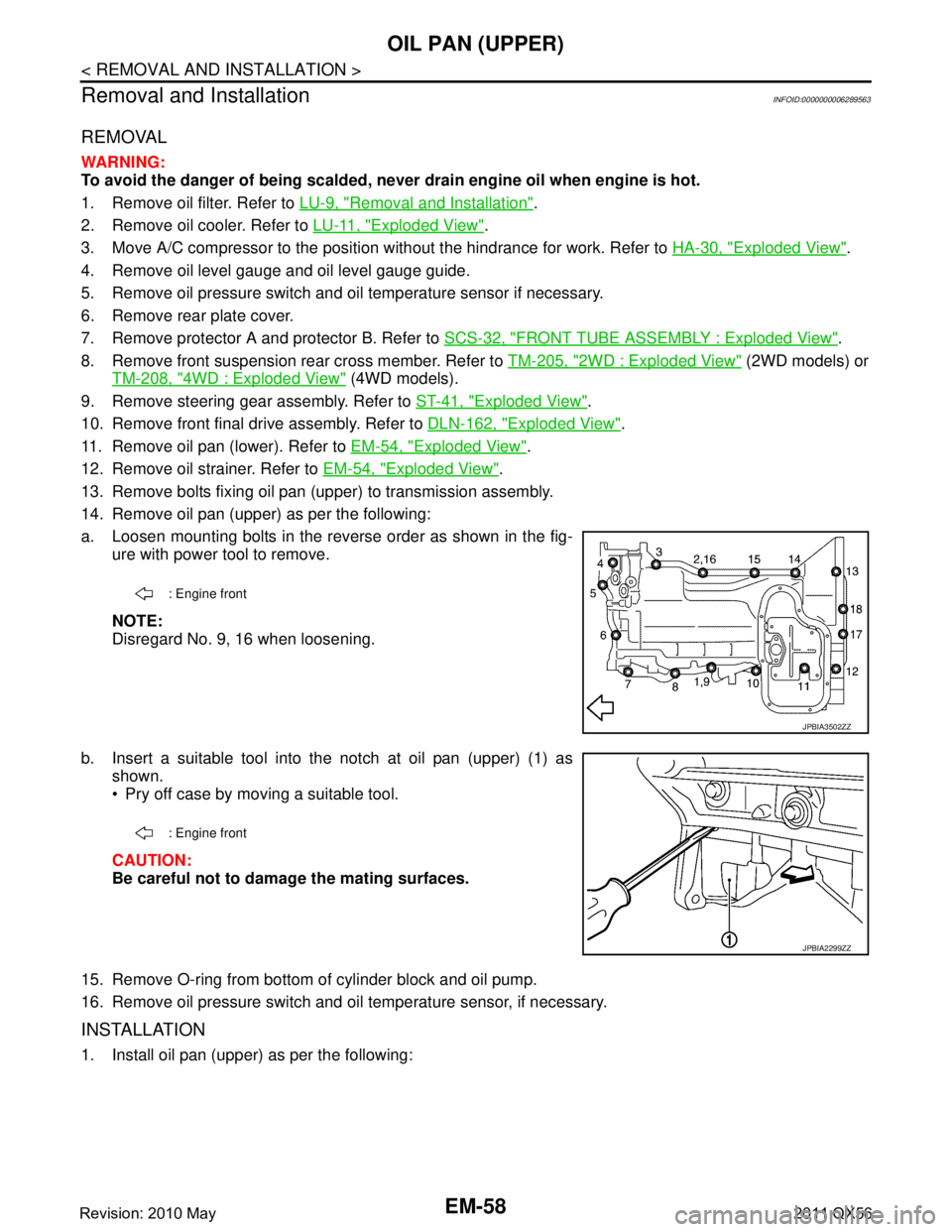
a. Loosen mounting bolts in the reverse order as shown in the fig- ure with power tool to remove.
NOTE:
Disregard No. 9, 16 when loosening.
b. Insert a suitable tool into the notch at oil pan (upper) (1) as shown.
Pry off case by moving a suitable tool.
CAUTION:
Be careful not to damage the mating surfaces.
15. Remove O-ring from bottom of cylinder block and oil pump.
16. Remove oil pressure switch and oil temperature sensor, if necessary.
INSTALLATION
1. Install oil pan (upper) as per the following:
: Engine front
JPBIA3502ZZ
: Engine front
JPBIA2299ZZ
Revision: 2010 May2011 QX56
Page 2621 of 5598
OIL PAN (UPPER)EM-59
< REMOVAL AND INSTALLATION >
C
DE
F
G H
I
J
K L
M A
EM
NP
O
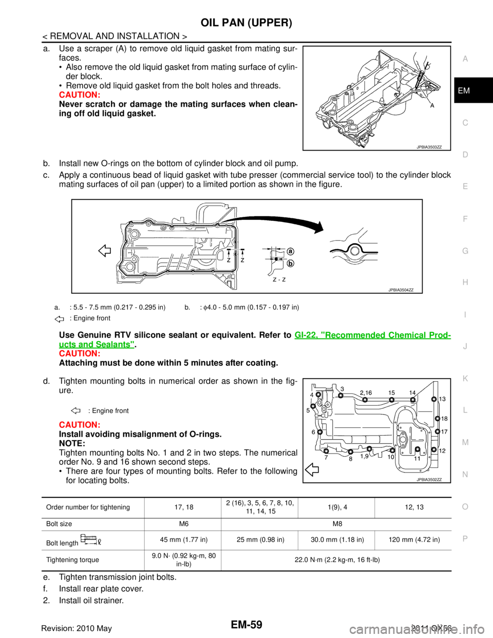
a. Use a scraper (A) to remove old liquid gasket from mating sur-
faces.
Also remove the old liquid gasket from mating surface of cylin-der block.
Remove old liquid gasket from the bolt holes and threads.
CAUTION:
Never scratch or damage th e mating surfaces when clean-
ing off old liquid gasket.
b. Install new O-rings on the bottom of cylinder block and oil pump.
c. Apply a continuous bead of liquid gasket with tube pre sser (commercial service tool) to the cylinder block
mating surfaces of oil pan (upper) to a limited portion as shown in the figure.
Use Genuine RTV silicone sealant or equivalent. Refer to GI-22, "
Recommended Chemical Prod-
ucts and Sealants".
CAUTION:
Attaching must be done with in 5 minutes after coating.
d. Tighten mounting bolts in numerical order as shown in the fig- ure.
CAUTION:
Install avoiding misal ignment of O-rings.
NOTE:
Tighten mounting bolts No. 1 and 2 in two steps. The numerical
order No. 9 and 16 shown second steps.
There are four types of mounting bolts. Refer to the following for locating bolts.
e. Tighten transmission joint bolts.
f. Install rear plate cover.
2. Install oil strainer.
JPBIA3503ZZ
a. : 5.5 - 7.5 mm (0.217 - 0.295 in) b. : φ4.0 - 5.0 mm (0.157 - 0.197 in)
: Engine front
JPBIA3504ZZ
: Engine front
JPBIA3502ZZ
Order number for tightening 17, 18 2 (16), 3, 5, 6, 7, 8, 10,
11, 14, 15 1(9), 4 12, 13
Bolt size M6 M8
Bolt length 45 mm (1.77 in) 25 mm (0.98 in) 30.0 mm (1.18 in) 120 mm (4.72 in)
Tightening torque 9.0 N· (0.92 kg-m, 80
in-lb) 22.0 N·m (2.2 kg-m, 16 ft-lb)
Revision: 2010 May2011 QX56
Page 2626 of 5598
EM-64
< REMOVAL AND INSTALLATION >
TIMING CHAIN
24. Remove oil pump and oil pump drive spacer.
25. Remove front oil seal from front cover using suitable tool. Use screwdriver for removal.
CAUTION:
Be careful not to damage front cover.
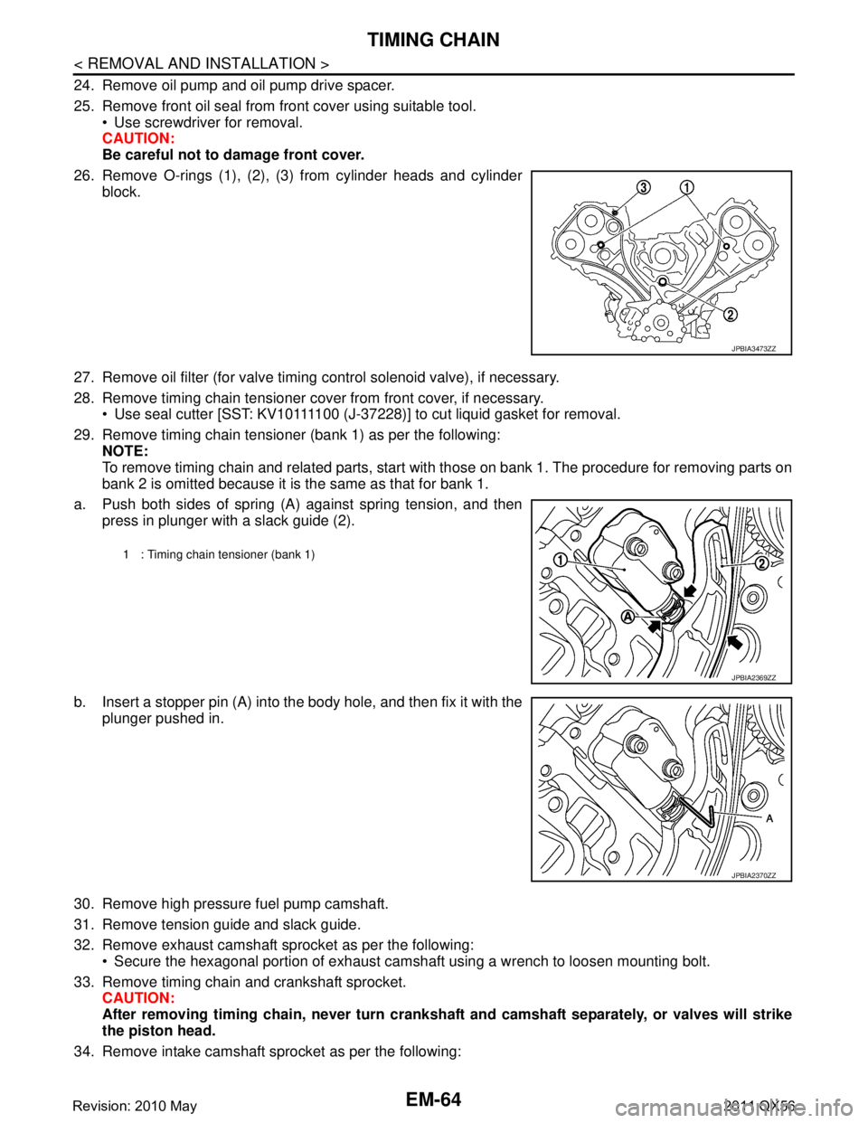
26. Remove O-rings (1), (2), (3) from cylinder heads and cylinder block.
27. Remove oil filter (for valve timing control solenoid valve), if necessary.
28. Remove timing chain tensioner cover from front cover, if necessary. Use seal cutter [SST: KV10111100 (J-37228)] to cut liquid gasket for removal.
29. Remove timing chain tensioner (bank 1) as per the following: NOTE:
To remove timing chain and related parts, start with those on bank 1. The procedure for removing parts on
bank 2 is omitted because it is the same as that for bank 1.
a. Push both sides of spring (A) against spring tension, and then press in plunger with a slack guide (2).
b. Insert a stopper pin (A) into the body hole, and then fix it with the
plunger pushed in.
30. Remove high pressure fuel pump camshaft.
31. Remove tension guide and slack guide.
32. Remove exhaust camshaft sprocket as per the following: Secure the hexagonal portion of exhaust camshaf t using a wrench to loosen mounting bolt.
33. Remove timing chain and crankshaft sprocket. CAUTION:
After removing timing chain, never turn cranksh aft and camshaft separately, or valves will strike
the piston head.
34. Remove intake camshaft sprocket as per the following:
JPBIA3473ZZ
1 : Timing chain tensioner (bank 1)
JPBIA2369ZZ
JPBIA2370ZZ
Revision: 2010 May2011 QX56
Page 2630 of 5598
EM-68
< REMOVAL AND INSTALLATION >
TIMING CHAIN
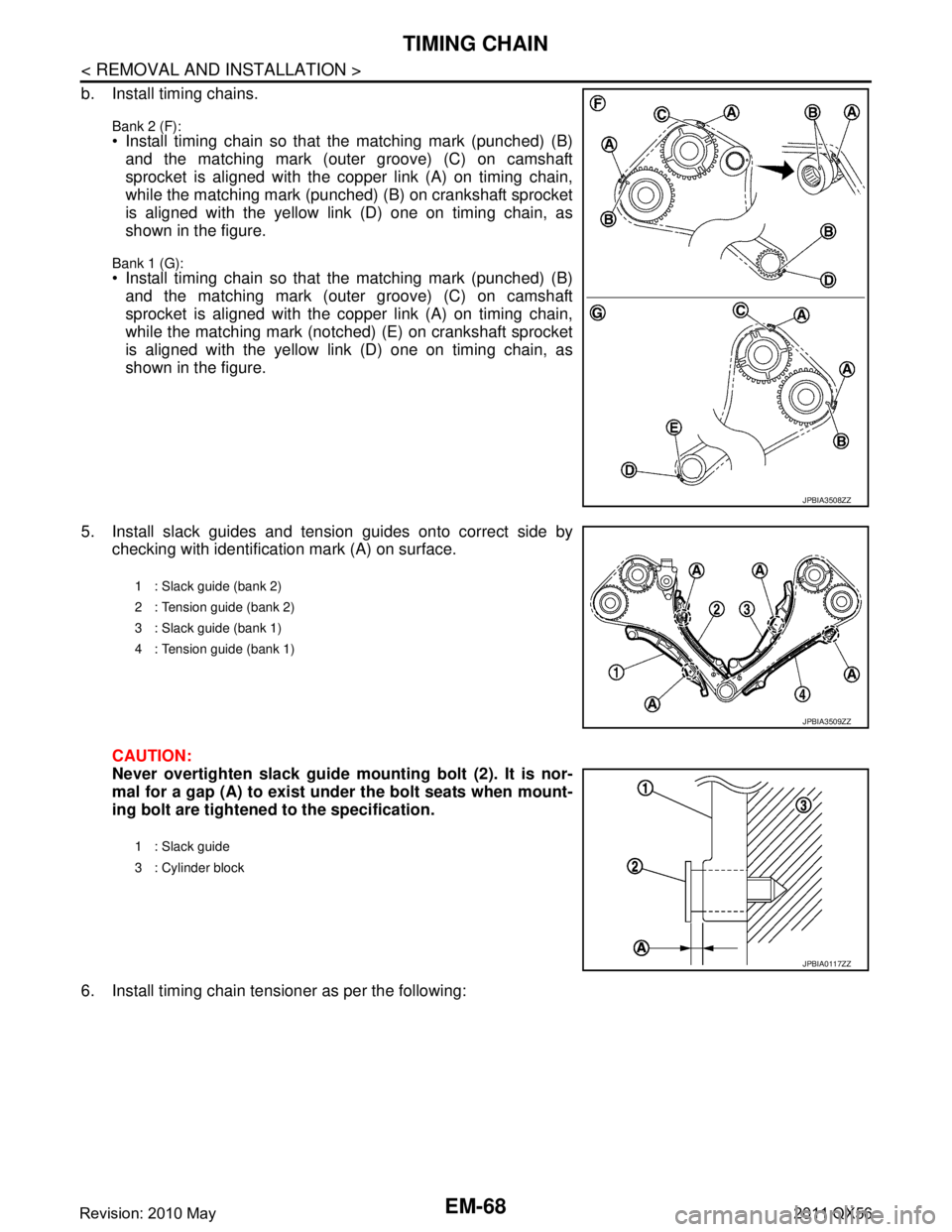
b. Install timing chains.
Bank 2 (F): Install timing chain so that the matching mark (punched) (B)and the matching mark (outer groove) (C) on camshaft
sprocket is aligned with the copper link (A) on timing chain,
while the matching mark (punched) (B) on crankshaft sprocket
is aligned with the yellow link (D) one on timing chain, as
shown in the figure.
Bank 1 (G): Install timing chain so that the matching mark (punched) (B)and the matching mark (outer groove) (C) on camshaft
sprocket is aligned with the copper link (A) on timing chain,
while the matching mark (notched) (E) on crankshaft sprocket
is aligned with the yellow link (D) one on timing chain, as
shown in the figure.
5. Install slack guides and tension guides onto correct side by checking with identification mark (A) on surface.
CAUTION:
Never overtighten slack guide mounting bolt (2). It is nor-
mal for a gap (A) to exist und er the bolt seats when mount-
ing bolt are tightened to the specification.
6. Install timing chain tensioner as per the following:
JPBIA3508ZZ
1 : Slack guide (bank 2)
2 : Tension guide (bank 2)
3 : Slack guide (bank 1)
4 : Tension guide (bank 1)
JPBIA3509ZZ
1 : Slack guide
3 : Cylinder block
JPBIA0117ZZ
Revision: 2010 May2011 QX56