2011 INFINITI QX56 ECO mode
[x] Cancel search: ECO modePage 4808 of 5598
DIAGNOSIS SYSTEM (AIR BAG)SRC-15
< SYSTEM DESCRIPTION >
C
DE
F
G
I
J
K L
M A
B
SRC
N
O P
DIAGNOSIS MODE
The diagnosis mode can only be switched when a malfuncti on is detected in the user mode. Malfunctioning
system is indicated according to blinking pattern of air bag warning lamp.
How to Read Air Bag Warning Lamp
1. Follow the procedures of “PROCEDURE TO CHANG E DIAGNOSIS MODE”, and switch to the diagnosis
mode.
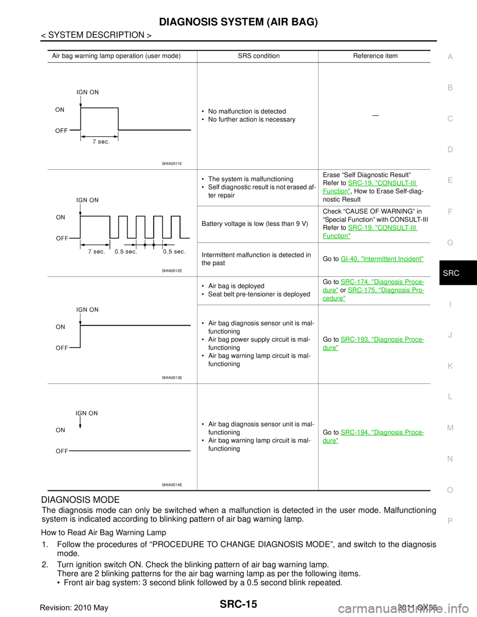
2. Turn ignition switch ON. Check the blinking pattern of air bag warning lamp. There are 2 blinking patterns for the air bag warning lamp as per the following items.
Front air bag system: 3 second blink followed by a 0.5 second blink repeated.
Air bag warning lamp operation (user mode) SRS condition Reference item
No malfunction is detected
No further action is necessary —
The system is malfunctioning
Self diagnostic result is not erased af- ter repair Erase “Self Diagnostic Result”
Refer to
SRC-19, "
CONSULT-III
Function", How to Erase Self-diag-
nostic Result
Battery voltage is low (less than 9 V) Check “CAUSE OF WARNING” in
“Special Function” with CONSULT-III
Refer to
SRC-19, "
CONSULT-III
Function"
Intermittent malfunction is detected in
the past Go to
GI-40, "Intermittent Incident"
Air bag is deployed
Seat belt pre-tensioner is deployed Go to
SRC-174, "Diagnosis Proce-
dure" or SRC-175, "Diagnosis Pro-
cedure"
Air bag diagnosis sensor unit is mal-
functioning
Air bag power supply circuit is mal- functioning
Air bag warning lamp circuit is mal-
functioning Go to
SRC-193, "
Diagnosis Proce-
dure"
Air bag diagnosis sensor unit is mal-
functioning
Air bag warning lamp circuit is mal- functioning Go to
SRC-194, "
Diagnosis Proce-
dure"
SHIA0011E
SHIA0012E
SHIA0013E
SHIA0014E
Revision: 2010 May2011 QX56
Page 4811 of 5598
SRC-18
< SYSTEM DESCRIPTION >
DIAGNOSIS SYSTEM (AIR BAG)
How to Erase Self-diagnostic Result
After a malfunction is repaired, turn the ignition swit ch OFF for one second or more, then turn ignition switch
ON. The diagnosis mode returns to the user mode. At that time the self-diagnostic result is cleared.
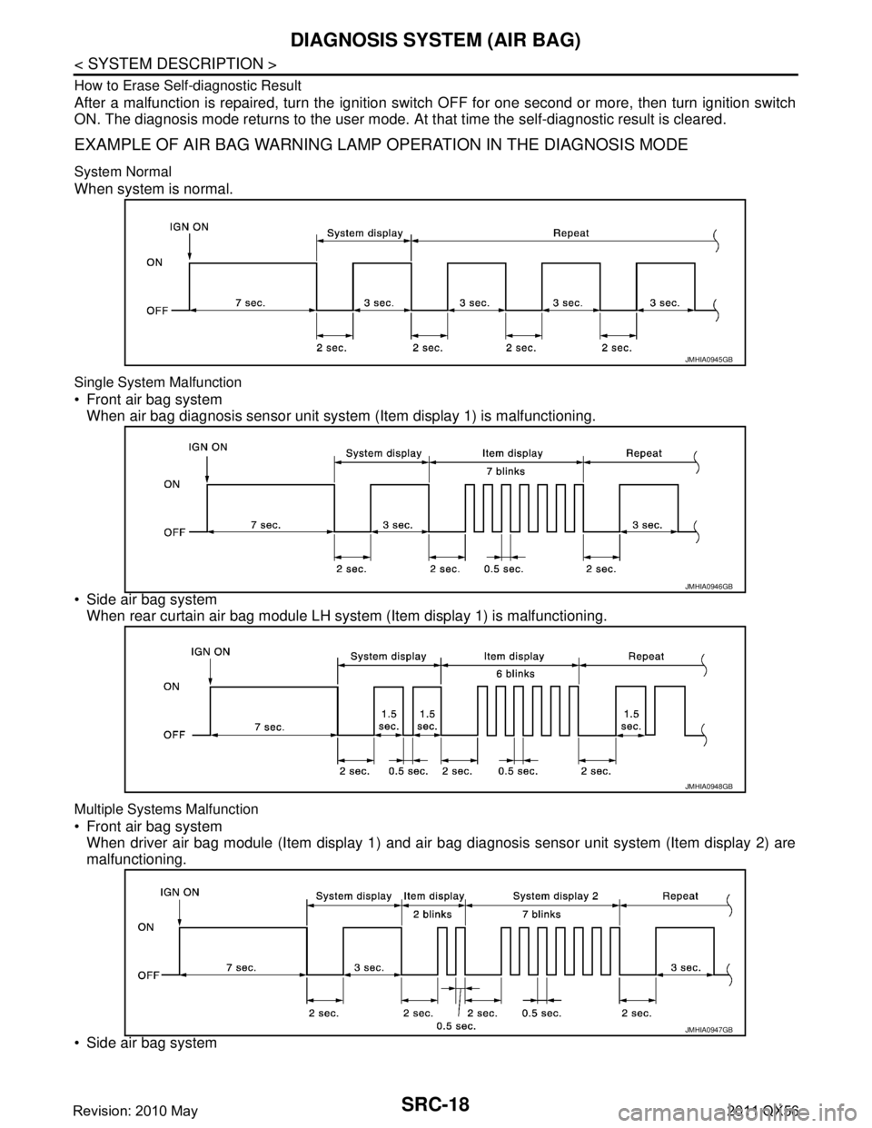
EXAMPLE OF AIR BAG WARNING LAMP OPERATION IN THE DIAGNOSIS MODE
System Normal
When system is normal.
Single System Malfunction
Front air bag system
When air bag diagnosis sensor unit system (Item display 1) is malfunctioning.
Side air bag system When rear curtain air bag module LH syst em (Item display 1) is malfunctioning.
Multiple Systems Malfunction
Front air bag system
When driver air bag module (Item display 1) and air bag diagnosis sensor unit system (Item display 2) are
malfunctioning.
Side air bag system
JMHIA0945GB
JMHIA0946GB
JMHIA0948GB
JMHIA0947GB
Revision: 2010 May2011 QX56
Page 4812 of 5598
DIAGNOSIS SYSTEM (AIR BAG)SRC-19
< SYSTEM DESCRIPTION >
C
DE
F
G
I
J
K L
M A
B
SRC
N
O P
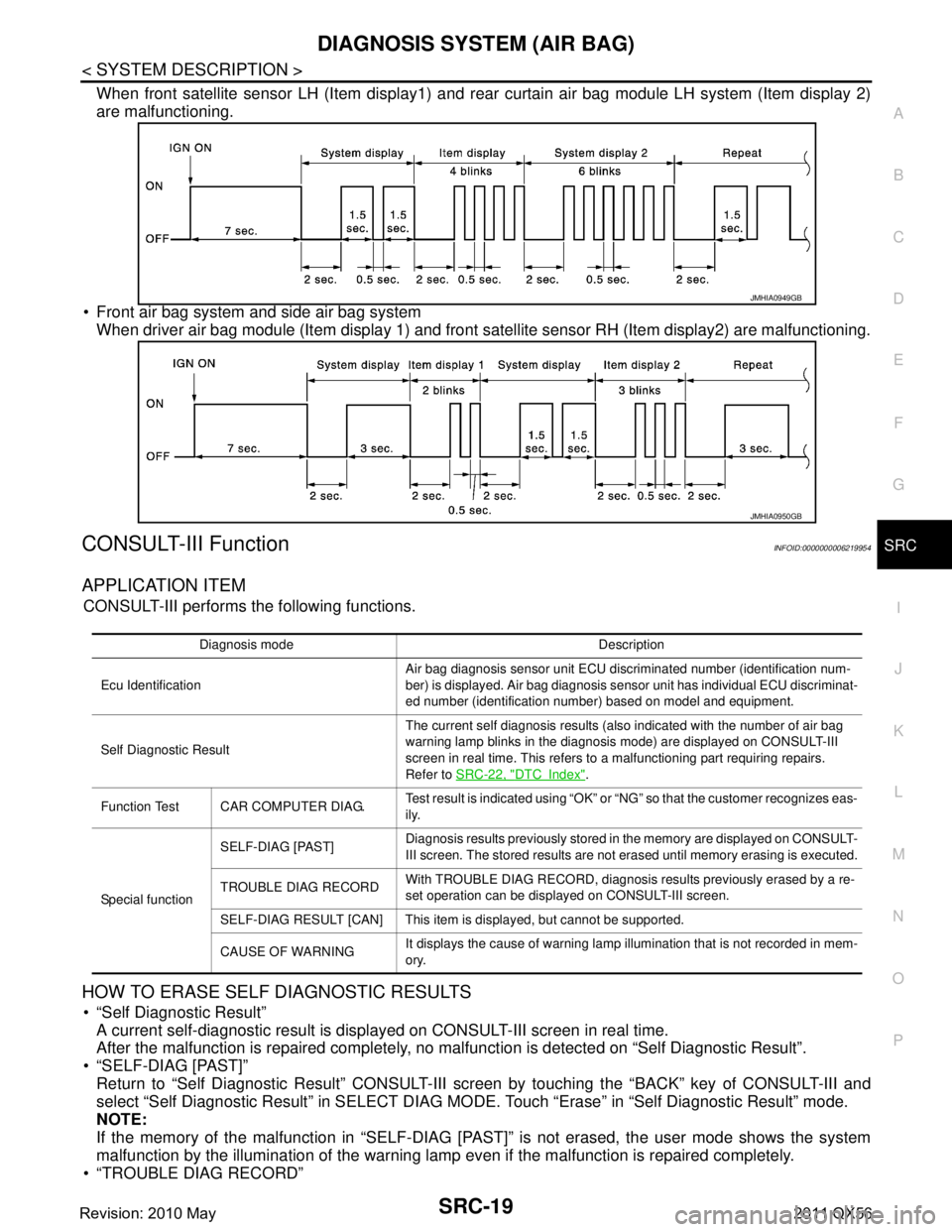
When front satellite sensor LH (Item display1) and r ear curtain air bag module LH system (Item display 2)
are malfunctioning.
Front air bag system and side air bag system When driver air bag module (Item display 1) and front satellite sensor RH (Item display2) are malfunctioning.
CONSULT-III FunctionINFOID:0000000006219954
APPLICATION ITEM
CONSULT-III performs the following functions.
HOW TO ERASE SELF DIAGNOSTIC RESULTS
“Self Diagnostic Result”
A current self-diagnostic result is displayed on CONSULT-III screen in real time.
After the malfunction is repaired completely, no malfunction is detected on “Self Diagnostic Result”.
“SELF-DIAG [PAST]” Return to “Self Diagnostic Result” CONSULT-III scr een by touching the “BACK” key of CONSULT-III and
select “Self Diagnostic Result” in SELECT DIAG MO DE. Touch “Erase” in “Self Diagnostic Result” mode.
NOTE:
If the memory of the malfunction in “SELF-DIAG [P AST]” is not erased, the user mode shows the system
malfunction by the illumination of the warning lamp even if the malfunction is repaired completely.
“TROUBLE DIAG RECORD”
JMHIA0949GB
JMHIA0950GB
Diagnosis mode Description
Ecu Identification Air bag diagnosis sensor unit ECU discriminated number (identification num-
ber) is displayed. Air bag diagnosis sensor unit has individual ECU discriminat-
ed number (identification number) based on model and equipment.
Self Diagnostic Result The current self diagnosis results (also indicated with the number of air bag
warning lamp blinks in the diagnosis mode) are displayed on CONSULT-III
screen in real time. This refers to a malfunctioning part requiring repairs.
Refer to
SRC-22, "
DTCIndex".
Function Test CAR COMPUTER DIAG. Test result is indicated using “OK” or “NG” so that the customer recognizes eas-
ily.
Special function SELF-DIAG [PAST]
Diagnosis results previously stored in the memory are displayed on CONSULT-
III screen. The stored results are not erased until memory erasing is executed.
TROUBLE DIAG RECORD With TROUBLE DIAG RECORD, diagnosis results previously erased by a re-
set operation can be displayed on CONSULT-III screen.
SELF-DIAG RESULT [CAN] This item is displayed, but cannot be supported.
CAUSE OF WARNING It displays the cause of warning lamp illumination that is not recorded in mem-
ory.
Revision: 2010 May2011 QX56
Page 4813 of 5598
![INFINITI QX56 2011 Factory Service Manual
SRC-20
< SYSTEM DESCRIPTION >
DIAGNOSIS SYSTEM (AIR BAG)
The memory of “TROUBLE DIAG RECORD” cannot be erased.
“SELF-DIAG RESULT [CAN]” Self-diagnosis result other than “SELF-DIAG R ESULT INFINITI QX56 2011 Factory Service Manual
SRC-20
< SYSTEM DESCRIPTION >
DIAGNOSIS SYSTEM (AIR BAG)
The memory of “TROUBLE DIAG RECORD” cannot be erased.
“SELF-DIAG RESULT [CAN]” Self-diagnosis result other than “SELF-DIAG R ESULT](/manual-img/42/57033/w960_57033-4812.png)
SRC-20
< SYSTEM DESCRIPTION >
DIAGNOSIS SYSTEM (AIR BAG)
The memory of “TROUBLE DIAG RECORD” cannot be erased.
“SELF-DIAG RESULT [CAN]” Self-diagnosis result other than “SELF-DIAG R ESULT [CAN]” is erased when touching “Erase”.
SPECIAL FUNCTION
CAUSE OF WARNING (AIR BAG)
This item indicates IGN low or high voltage condition.
The air bag warning lamp blink in user mode when the battery voltage is lowered to the voltage value (less
than 9 V or highroad to the voltage value (more than 16V ) at which the SRS cannot be operated normally. The
air bag warning lamp turns OFF after the battery voltage returns to normal status after blinking.
In such a case, the DTC memory is not performed and changing to the self-diagnostic mode by IGN operation
cannot be performed while the air bag warning lamp illumi nates. “NO DTC” is displayed even if the malfunc-
tioning parts are checked by CONSULT-III.
This function records the following items.
CAUSE OF WARNING (OCCUPANT DETSCTION SYSTEM)
Detection status and detection record is displayed w hen air bag warning lamp blinks due to occupant detec-
tion function stop. Change to trouble diagnosis mode by ignition switch is not possible while warning lamp is
blinking due to occupant detection function stop. “NO DT C” is displayed even if the malfunctioning parts are
checked by CONSULT-III.
Display contents of CONSULT-III Description
Air bag IGN VOLT COND
“LOW” is displayed when IGN low or high voltage is detected. If not, “OK” is
displayed.
IGN VOLT TIME Number of times of IGN low or high voltage is detected.
LOW V RECORED Number of times of IGN ON after IGN low or high voltage is detected at first.
Display contents of CONSULT-III Description
Occupant detection
system FUNCTION STATUS
“ON” or “STOP” is displayed according to occupant detection status that
is recognized by occupant detection system control unit.
“STOP” is displayed when occupant detection function is stopped, if not, “ON” is displayed.
STOP DETECTION Displays number of times occupant detection function stop which is detect-
ed by occupant detection system control unit is displayed.
DETECTION RECORD Displays number of times of IGN ON since first detection of occupant detec-
tion function stop is displayed.
Revision: 2010 May2011 QX56
Page 4830 of 5598
DIAGNOSIS AND REPAIR WORK FLOWSRC-37
< BASIC INSPECTION >
C
DE
F
G
I
J
K L
M A
B
SRC
N
O P
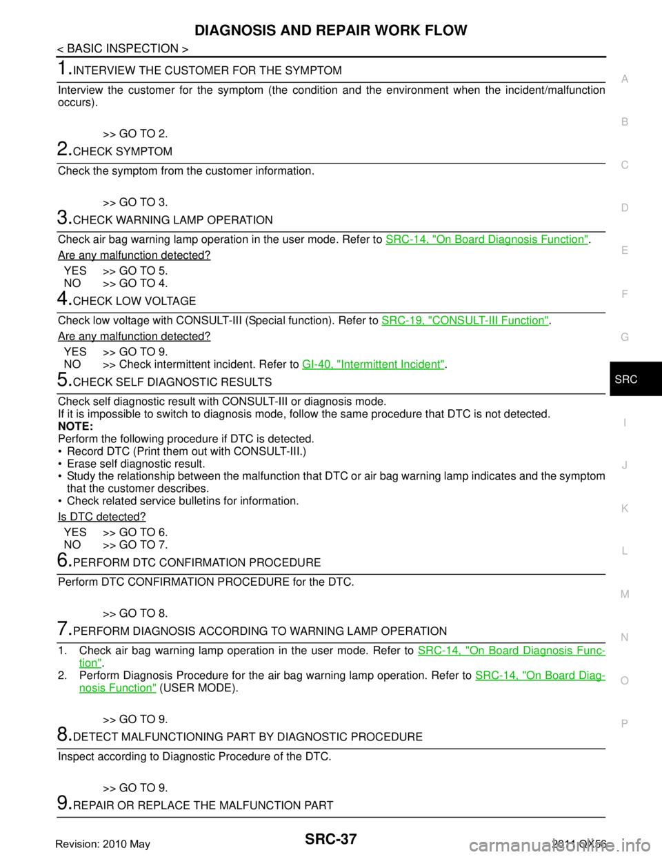
1.INTERVIEW THE CUSTOMER FOR THE SYMPTOM
Interview the customer for the symptom (the condi tion and the environment when the incident/malfunction
occurs).
>> GO TO 2.
2.CHECK SYMPTOM
Check the symptom from the customer information.
>> GO TO 3.
3.CHECK WARNING LAMP OPERATION
Check air bag warning lamp operation in the user mode. Refer to SRC-14, "
On Board Diagnosis Function".
Are any malfunction detected?
YES >> GO TO 5.
NO >> GO TO 4.
4.CHECK LOW VOLTAGE
Check low voltage with CONSULT-III (Special function). Refer to SRC-19, "
CONSULT-III Function".
Are any malfunction detected?
YES >> GO TO 9.
NO >> Check intermittent incident. Refer to GI-40, "
Intermittent Incident".
5.CHECK SELF DIAGNOSTIC RESULTS
Check self diagnostic result with CONSULT-III or diagnosis mode.
If it is impossible to switch to diagnosis mode, follow the same pr ocedure that DTC is not detected.
NOTE:
Perform the following procedure if DTC is detected.
Record DTC (Print them out with CONSULT-III.)
Erase self diagnostic result.
Study the relationship between the malfunction that DT C or air bag warning lamp indicates and the symptom
that the customer describes.
Check related service bulletins for information.
Is DTC detected?
YES >> GO TO 6.
NO >> GO TO 7.
6.PERFORM DTC CONFIRMATION PROCEDURE
Perform DTC CONFIRMATION PROCEDURE for the DTC.
>> GO TO 8.
7.PERFORM DIAGNOSIS ACCORDING TO WARNING LAMP OPERATION
1. Check air bag warning lamp operation in the user mode. Refer to SRC-14, "
On Board Diagnosis Func-
tion".
2. Perform Diagnosis Procedure for the air bag warning lamp operation. Refer to SRC-14, "
On Board Diag-
nosis Function" (USER MODE).
>> GO TO 9.
8.DETECT MALFUNCTIONING PA RT BY DIAGNOSTIC PROCEDURE
Inspect according to Diagnostic Procedure of the DTC.
>> GO TO 9.
9.REPAIR OR REPLACE THE MALFUNCTION PART
Revision: 2010 May2011 QX56
Page 4833 of 5598

SRC-40
< BASIC INSPECTION >
INSPECTION AND ADJUSTMENT
“Complete” is displayed on “zero point reset current status” if the seat is reinstalled by seat removal
and installation, or “zero poin t reset” is already performed.
“Zero point reset current status” displays “Incompl ete” if a new seat is installed. When turning key
switch ON without performing zero point reset, air bag warning lamp blinks. When zero point reset is
performed, air bag wa rning lamp turns OFF.
Air bag warning lamp blinks in user mode only.
Air bag sensor unit does not record whethe r or not zero point reset is performed.
Is condition
“ALREADY PERFORMED”?
YES >> Print out “ZERO POINT RESET CURRENT STATUS” screen, and inspection end.
NO >> Check condition as per the following, and perform zero point reset again. Passenger seat is occupied by an object.
Excessive vibration is applied while performing zero point reset.
Occupant detection system is malfunctioning.NOTE:
If “Incomplete” is displayed on “zero point reset cu rrent status”, zero point reset is not completed
normally. Check the condition as per the following and perform zero point reset again.
Passenger seat is occupied by an object.
Excessive vibration is applied while performing zero point reset.
Occupant detection system is malfunctioning.
Revision: 2010 May2011 QX56
Page 5054 of 5598
POWER STEERING CONTROL UNITSTC-9
< ECU DIAGNOSIS INFORMATION >
C
DE
F
H I
J
K L
M A
B
STC
N
O PCAUTION:
When using circuit tester or osci lloscope to measure voltage for in spection, be sure not to forcibly
extend any connector terminals.
Fail-Safe INFOID:0000000006256122
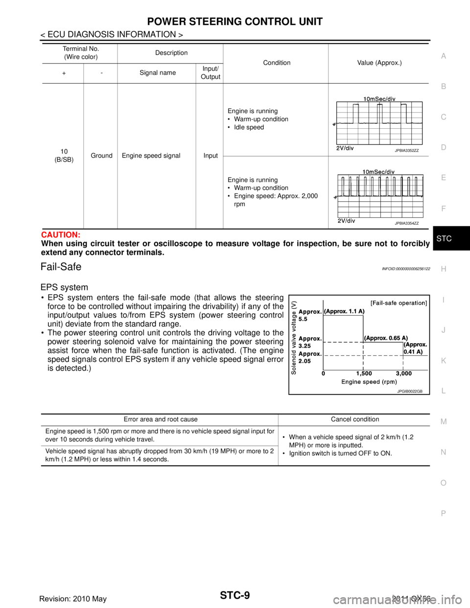
EPS system
EPS system enters the fail-safe mode (that allows the steering
force to be controlled without impair ing the drivability) if any of the
input/output values to/from EPS system (power steering control
unit) deviate from the standard range.
The power steering control unit controls the driving voltage to the
power steering solenoid valve for maintaining the power steering
assist force when the fail-safe function is activated. (The engine
speed signals control EPS system if any vehicle speed signal error
is detected.)
10
(B/SB) Ground Engine speed signal Input Engine is running
Warm-up condition
Idle speed
Engine is running
Warm-up condition
Engine speed: Approx. 2,000
rpm
Te r m i n a l N o .
(Wire color) Description
Condition Value (Approx.)
+ - Signal name Input/
OutputJPBIA3352ZZ
JPBIA3354ZZ
JPGIB0022GB
Error area and root cause Cancel condition
Engine speed is 1,500 rpm or more and there is no vehicle speed signal input for
over 10 seconds during vehicle travel. When a vehicle speed signal of 2 km/h (1.2
MPH) or more is inputted.
Ignition switch is turned OFF to ON.
Vehicle speed signal has abruptly dropped from 30 km/h (19 MPH) or more to 2
km/h (1.2 MPH) or less within 1.4 seconds.
Revision: 2010 May2011 QX56
Page 5102 of 5598
![INFINITI QX56 2011 Factory Service Manual
TM-14
< SYSTEM DESCRIPTION >[7AT: RE7R01B]
COMPONENT PARTS
A/T CONTROL SYSTEM : Tow Mode Switch
INFOID:0000000006226756
Tow mode switch is integrated in to
Tow mode switch is integrated in to SN INFINITI QX56 2011 Factory Service Manual
TM-14
< SYSTEM DESCRIPTION >[7AT: RE7R01B]
COMPONENT PARTS
A/T CONTROL SYSTEM : Tow Mode Switch
INFOID:0000000006226756
Tow mode switch is integrated in to
Tow mode switch is integrated in to SN](/manual-img/42/57033/w960_57033-5101.png)
TM-14
< SYSTEM DESCRIPTION >[7AT: RE7R01B]
COMPONENT PARTS
A/T CONTROL SYSTEM : Tow Mode Switch
INFOID:0000000006226756
Tow mode switch is integrated in to
Tow mode switch is integrated in to SNOW MODE /TOW MODE/VDC OFF switch assembly (2WD models)
or 4WD switch assembly (4WD models).
When tow mode switch is pressed while tow mode indicator lamp on combination meter is OFF, the tow mode turns ON and tow mode indicator lamp turns ON.
When tow mode switch is pressed while tow mode indicator lamp on combination meter is ON, the tow mode
turns OFF and tow mode indicator lamp turns OFF.
A/T CONTROL SYSTEM : A/ T CHECK Indicator LampINFOID:0000000006226757
A/T CHECK INDICATOR LAMP
Turns ON when ignition switch turns ON and turns OFF when the system is normal, for bulb check purposes.
A/T CONTROL SYSTEM : Tow Mode Indicator LampINFOID:0000000006226758
TOW MODE INDICATOR LAMP
Turns ON when tow mode is switched to operational status (ON) by tow mode switch.
A/T CONTROL SYSTEM : Selector Lever Position IndicatorINFOID:0000000006226759
Indicates selector lever position.
A/T SHIFT LOCK SYSTEM
Condition (status) A/T CHECK indicator lamp
Ignition switch OFF OFF
For approx. 2 seconds after the ignition switch is turned ON ON
Approx. 2 seconds after ignition switch is turned ON OFF
A/T is malfunctioning OFF
Condition (status) Tow mode indicator lamp
Ignition switch OFF OFF
When ignition switch turns ON OFF
Press tow mode switch while tow mode indicator lamp is OFF. ON
Press tow mode switch while tow mode indicator lamp is ON. OFF
Revision: 2010 May2011 QX56