2011 INFINITI QX56 wheel bolts
[x] Cancel search: wheel boltsPage 3405 of 5598
![INFINITI QX56 2011 Factory Service Manual
INSTRUMENT PANEL ASSEMBLYIP-15
< REMOVAL AND INSTALLATION >
C
DE
F
G H
I
K L
M A
B
IP
N
O P
[ ]:Number indicates step in removal procedures.
WARNING:
Before servicing, turn igni tion switch OFF, disc INFINITI QX56 2011 Factory Service Manual
INSTRUMENT PANEL ASSEMBLYIP-15
< REMOVAL AND INSTALLATION >
C
DE
F
G H
I
K L
M A
B
IP
N
O P
[ ]:Number indicates step in removal procedures.
WARNING:
Before servicing, turn igni tion switch OFF, disc](/manual-img/42/57033/w960_57033-3404.png)
INSTRUMENT PANEL ASSEMBLYIP-15
< REMOVAL AND INSTALLATION >
C
DE
F
G H
I
K L
M A
B
IP
N
O P
[ ]:Number indicates step in removal procedures.
WARNING:
Before servicing, turn igni tion switch OFF, disconnect battery ne gative terminal, and wait 3 minutes or
more.
CAUTION:
When removing, always use a remover tool that is made of plastic.
REMOVAL
1. Remove instrument lower cover.
1. Pull disengaged pawls downward.
2. Pull back instrument lower cover.
3. Disconnect harness connectors.
Squawker LH [20] [20]
Instrument lower panel LH [21] [2] [2] [21]
Disconnect meter control switch
harness connector [22] [3] [3] [22]
Driver air bag module [23] [23]
Steering wheel [24] [24]
Steering column cover [25] [25]
Combination switch [26] [26]
Spiral cable [27] [27]
Cluster lid A [28] [4] [4] [28]
Combination meter [29] [5] [29]
Instrument finisher A [5]
Upper ventilator grille [30] [30]
Center speaker [31] [31]
Cluster lid C [32] [6] [6] [32]
Cluster lid C lower [33] [7] [33]
AV control unit [34] [8] [34]
Cluster lid D [35] [7] [35]
Front display unit [36] [8] [36]
instrument panel assembly
mounting screws and bolts [37] [37]
Squawker LH harness clip [38] [38]
Instrument panel assembly [39] [39]
Instrument finisher B [40]
PA R T S
INSTRU-
MENT
PA N E L
ASSEMBLY COMBINA-
TION
METER FRONT
DISPLAY UNIT AV c o n t r o l
unit INSTRU-
MENT
FINISHER A INSTRU-
MENT
FINISHER B CENTER
CONSOLE
ASSEMBLY
: Pawl
JMJIA3828ZZ
Revision: 2010 May2011 QX56
Page 3409 of 5598
INSTRUMENT PANEL ASSEMBLYIP-19
< REMOVAL AND INSTALLATION >
C
DE
F
G H
I
K L
M A
B
IP
N
O P
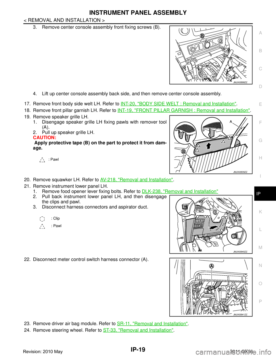
3. Remove center console assembly front fixing screws (B).
4. Lift up center console assembly back side, and then remove center console assembly.
17. Remove front body side welt LH. Refer to INT-20, "
BODY SIDE WELT : Removal and Installation".
18. Remove front pillar garnish LH. Refer to INT-19, "
FRONT PILLAR GARNISH : Removal and Installation".
19. Remove speaker grille LH. 1. Disengage speaker grille LH fixing pawls with remover tool (A).
2. Pull up speaker grille LH.
CAUTION:
Apply protective tape (B) on the part to protect it from dam-
age.
20. Remove squawker LH. Refer to AV-218, "
Removal and Installation".
21. Remove instrument lower panel LH. 1. Remove food opener lever fixing bolts. Refer to DLK-238, "
Removal and Installation"
2. Pull back instrument lower panel LH, and then disengage
the clips and pawl.
3. Disconnect harness connectors and aspirator duct.
22. Disconnect meter control s witch harness connector (A).
23. Remove driver air bag module. Refer to SR-11, "
Removal and Installation".
24. Remove steering wheel. Refer to ST-33, "
Removal and Installation".
JMJIA3898ZZ
: Pawl
JMJIA3839ZZ
: Clip
: Pawl
JMJIA3840ZZ
JMJIA3841ZZ
Revision: 2010 May2011 QX56
Page 3702 of 5598
MA-32
< PERIODIC MAINTENANCE >
CHASSIS MAINTENANCE
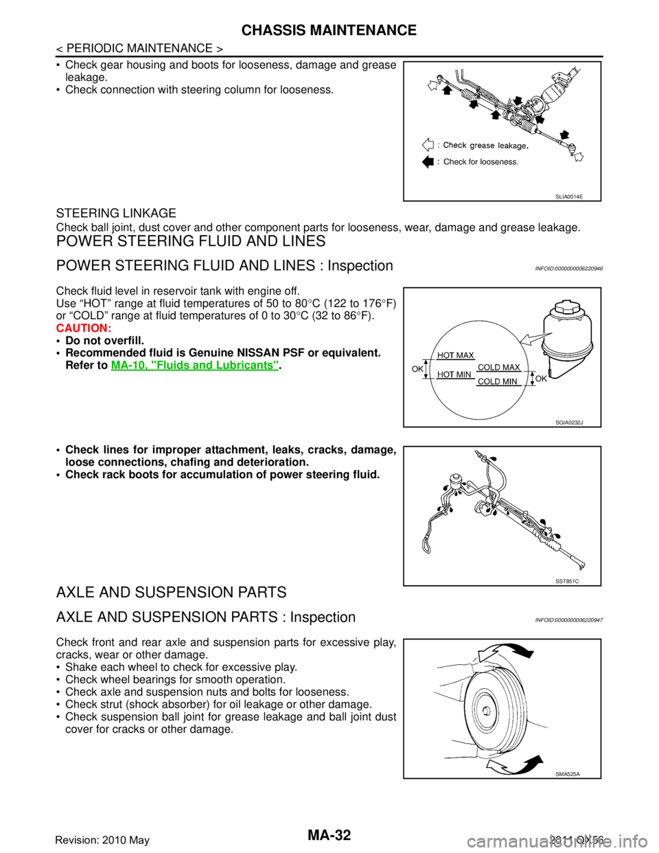
Check gear housing and boots for looseness, damage and greaseleakage.
Check connection with steering column for looseness.
STEERING LINKAGE
Check ball joint, dust cover and other component parts for looseness, wear, damage and grease leakage.
POWER STEERING FLUID AND LINES
POWER STEERING FLUID AND LINES : InspectionINFOID:0000000006220946
Check fluid level in reservoir tank with engine off.
Use “HOT” range at fluid temperatures of 50 to 80 °C (122 to 176 °F)
or “COLD” range at fluid temperatures of 0 to 30 °C (32 to 86 °F).
CAUTION:
Do not overfill.
Recommended fluid is Genuine NISSAN PSF or equivalent.
Refer to MA-10, "
Fluids and Lubricants".
Check lines for improper attachment, leaks, cracks, damage, loose connections, chaf ing and deterioration.
Check rack boots for accumulati on of power steering fluid.
AXLE AND SUSPENSION PARTS
AXLE AND SUSPENSION PARTS : InspectionINFOID:0000000006220947
Check front and rear axle and suspension parts for excessive play,
cracks, wear or other damage.
Shake each wheel to check for excessive play.
Check wheel bearings for smooth operation.
Check axle and suspension nuts and bolts for looseness.
Check strut (shock absorber) for oil leakage or other damage.
Check suspension ball joint for grease leakage and ball joint dust
cover for cracks or other damage.
SLIA0014E
SGIA0232J
SST851C
SMA525A
Revision: 2010 May2011 QX56
Page 4204 of 5598
RAX-8
< REMOVAL AND INSTALLATION >
REAR WHEEL HUB AND HOUSING
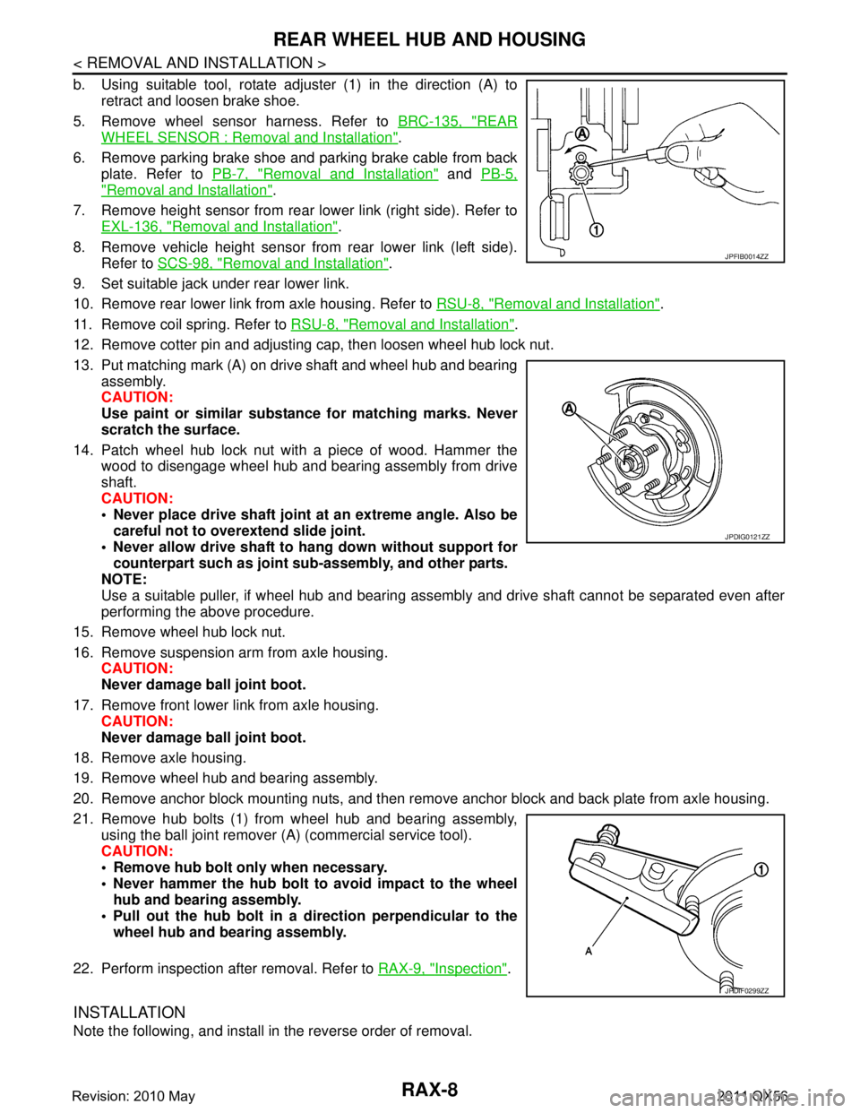
b. Using suitable tool, rotate adjuster (1) in the direction (A) toretract and loosen brake shoe.
5. Remove wheel sensor harness. Refer to BRC-135, "
REAR
WHEEL SENSOR : Removal and Installation".
6. Remove parking brake shoe and parking brake cable from back plate. Refer to PB-7, "
Removal and Installation" and PB-5,
"Removal and Installation".
7. Remove height sensor from rear lower link (right side). Refer to EXL-136, "
Removal and Installation".
8. Remove vehicle height sensor from rear lower link (left side). Refer to SCS-98, "
Removal and Installation".
9. Set suitable jack under rear lower link.
10. Remove rear lower link from axle housing. Refer to RSU-8, "
Removal and Installation".
11. Remove coil spring. Refer to RSU-8, "
Removal and Installation".
12. Remove cotter pin and adjusting cap, then loosen wheel hub lock nut.
13. Put matching mark (A) on drive shaft and wheel hub and bearing assembly.
CAUTION:
Use paint or similar substance for matching marks. Never
scratch the surface.
14. Patch wheel hub lock nut with a piece of wood. Hammer the wood to disengage wheel hub and bearing assembly from drive
shaft.
CAUTION:
Never place drive shaft joint at an extreme angle. Also be
careful not to over extend slide joint.
Never allow drive shaft to ha ng down without support for
counterpart such as joint sub-assembly, and other parts.
NOTE:
Use a suitable puller, if wheel hub and bearing assembly and drive shaft cannot be separated even after
performing the above procedure.
15. Remove wheel hub lock nut.
16. Remove suspension arm from axle housing. CAUTION:
Never damage ball joint boot.
17. Remove front lower link from axle housing. CAUTION:
Never damage ball joint boot.
18. Remove axle housing.
19. Remove wheel hub and bearing assembly.
20. Remove anchor block mounting nuts, and then remove anchor block and back plate from axle housing.
21. Remove hub bolts (1) from wheel hub and bearing assembly, using the ball joint remover (A) (commercial service tool).
CAUTION:
Remove hub bolt only when necessary.
Never hammer the hub bolt to avoid impact to the wheel
hub and bearing assembly.
Pull out the hub bolt in a direction perpendicular to the wheel hub and bearing assembly.
22. Perform inspection after removal. Refer to RAX-9, "
Inspection".
INSTALLATION
Note the following, and install in the reverse order of removal.
JPFIB0014ZZ
JPDIG0121ZZ
JPDIF0299ZZ
Revision: 2010 May2011 QX56
Page 4205 of 5598
REAR WHEEL HUB AND HOUSINGRAX-9
< REMOVAL AND INSTALLATION >
CEF
G H
I
J
K L
M A
B
RAX
N
O P
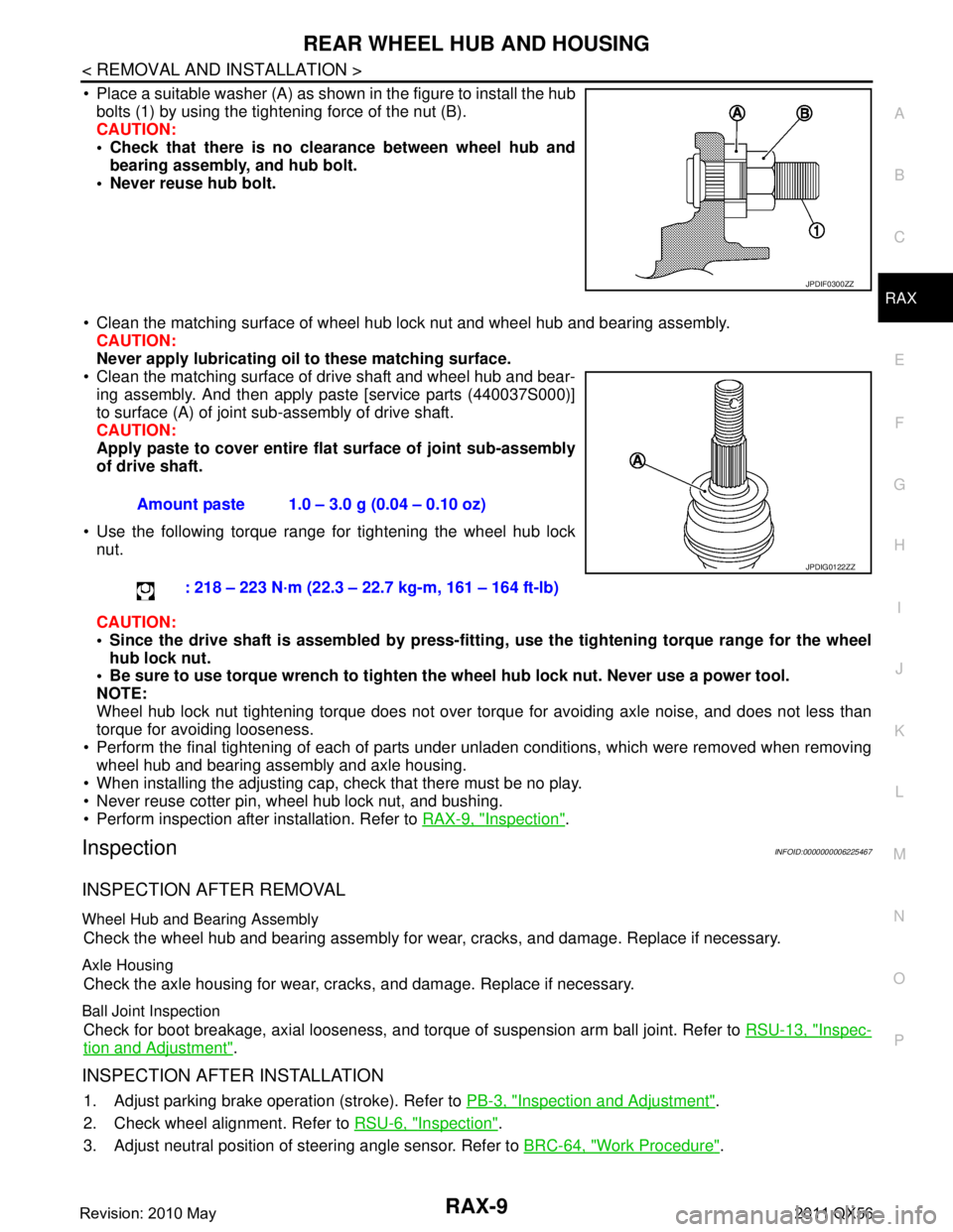
Place a suitable washer (A) as shown in the figure to install the hub bolts (1) by using the tightening force of the nut (B).
CAUTION:
Check that there is no cl earance between wheel hub and
bearing assembly, and hub bolt.
Never reuse hub bolt.
Clean the matching surface of wheel hub lock nut and wheel hub and bearing assembly. CAUTION:
Never apply lubricating oi l to these matching surface.
Clean the matching surface of drive shaft and wheel hub and bear-
ing assembly. And then apply paste [service parts (440037S000)]
to surface (A) of joint sub-assembly of drive shaft.
CAUTION:
Apply paste to cover entire fl at surface of joint sub-assembly
of drive shaft.
Use the following torque range for tightening the wheel hub lock nut.
CAUTION:
Since the drive shaft is assembled by press-fitting , use the tightening torque range for the wheel
hub lock nut.
Be sure to use torque wrench to tighten th e wheel hub lock nut. Never use a power tool.
NOTE:
Wheel hub lock nut tightening torque does not over tor que for avoiding axle noise, and does not less than
torque for avoiding looseness.
Perform the final tightening of each of parts under unladen conditions, which were removed when removing wheel hub and bearing assembly and axle housing.
When installing the adjusting cap, check that there must be no play.
Never reuse cotter pin, wheel hub lock nut, and bushing.
Perform inspection after installation. Refer to RAX-9, "
Inspection".
InspectionINFOID:0000000006225467
INSPECTION AFTER REMOVAL
Wheel Hub and Bearing Assembly
Check the wheel hub and bearing assembly for wear, cracks, and damage. Replace if necessary.
Axle Housing
Check the axle housing for wear, cracks, and damage. Replace if necessary.
Ball Joint Inspection
Check for boot breakage, axial looseness, and torque of suspension arm ball joint. Refer to RSU-13, "Inspec-
tion and Adjustment".
INSPECTION AFTER INSTALLATION
1. Adjust parking brake operation (stroke). Refer to PB-3, "Inspection and Adjustment".
2. Check wheel alignment. Refer to RSU-6, "
Inspection".
3. Adjust neutral position of steering angle sensor. Refer to BRC-64, "
Work Procedure".
JPDIF0300ZZ
Amount paste 1.0 – 3.0 g (0.04 – 0.10 oz)
: 218 – 223 N·m (22.3 – 22.7 kg-m, 161 – 164 ft-lb)
JPDIG0122ZZ
Revision: 2010 May2011 QX56
Page 4208 of 5598
RAX-12
< REMOVAL AND INSTALLATION >
REAR DRIVE SHAFT
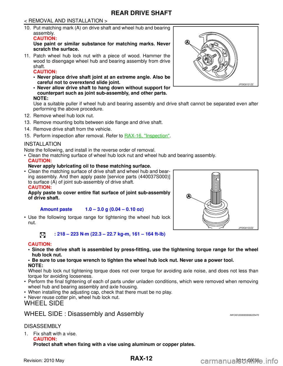
10. Put matching mark (A) on drive shaft and wheel hub and bearingassembly.
CAUTION:
Use paint or similar substance for matching marks. Never
scratch the surface.
11. Patch wheel hub lock nut with a piece of wood. Hammer the wood to disengage wheel hub and bearing assembly from drive
shaft.
CAUTION:
Never place drive shaft joint at an extreme angle. Also becareful not to over extend slide joint.
Never allow drive shaft to ha ng down without support for
counterpart such as joint sub-assembly, and other parts.
NOTE:
Use a suitable puller if wheel hub and bearing assembly and drive shaft cannot be separated even after
performing the above procedure.
12. Remove wheel hub lock nut.
13. Remove mounting bolts between side flange and drive shaft.
14. Remove drive shaft from the vehicle.
15. Perform inspection after removal. Refer to RAX-16, "
Inspection".
INSTALLATION
Note the following, and install in the reverse order of removal.
Clean the matching surface of wheel hub lock nut and wheel hub and bearing assembly.
CAUTION:
Never apply lubricating oi l to these matching surface.
Clean the matching surface of drive shaft and wheel hub and bear- ing assembly. And then apply paste [service parts (440037S000)]
to surface (A) of joint sub-assembly of drive shaft.
CAUTION:
Apply paste to cover entire fl at surface of joint sub-assembly
of drive shaft.
Use the following torque range for tightening the wheel hub lock nut.
CAUTION:
Since the drive shaft is assembled by press-fittin g, use the tightening torque range for the wheel
hub lock nut.
Be sure to use torque wrench to tighten th e wheel hub lock nut. Never use a power tool.
NOTE:
Wheel hub lock nut tightening torque does not over torque for avoiding axle noise, and does not less than
torque for avoiding looseness.
Perform the final tightening of each of parts under unladen conditions, which were removed when removing
wheel hub and bearing assembly and axle housing.
When installing the adjusting cap, check that there must be no play.
Never reuse cotter pin, wheel hub lock nut.
WHEEL SIDE
WHEEL SIDE : Disassembly and AssemblyINFOID:0000000006225470
DISASSEMBLY
1. Fix shaft with a vise. CAUTION:
Protect shaft when fixing with a vi se using aluminum or copper plates.
JPDIG0121ZZ
Amount paste 1.0 – 3.0 g (0.04 – 0.10 oz)
: 218 – 223 N·m (22.3 – 22.7 kg-m, 161 – 164 ft-lb)
JPDIG0122ZZ
Revision: 2010 May2011 QX56
Page 4266 of 5598
REAR SHOCK ABSORBERRSU-11
< REMOVAL AND INSTALLATION >
C
DF
G H
I
J
K L
M A
B
RSU
N
O P
Inadvertent piping removal causes fluid to splatter.
2. Remove tires with power tool. Refer to WT-64, "
Removal and Installation".
3. Remove height sensor from rear lower link (right side). Refer to EXL-136, "
Removal and Installation".
4. Remove vehicle height sensor from rear lower link (left side). Refer to SCS-98, "
Removal and Installa-
tion".
5. Remove air tube from shock absorber assembly. Refer to SCS-95, "
Removal and Installation".
6. Remove middle tube assembly from shock absorber assembly. (With HBMC) Refer to SCS-44, "
REAR
TUBE ASSEMBLY : Removal and Installation".
7. Remove shock absorber mounting bolt (lower side).
8. Remove piston rod lock nut.
9. Remove bracket, bushings, and shock absorber. (With HBMC)
10. Remove washers, bushings, and shock absorber. (Without HBMC)
11. Perform inspection after removal. Refer to RSU-11, "
Inspection and Adjustment".
INSTALLATION
Note the following, and install in the reverse order of removal.
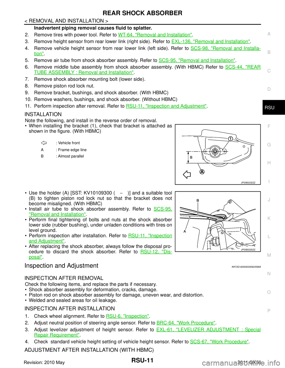
When installing the bracket (1), check that bracket is attached as
shown in the figure. (With HBMC)
Use the holder (A) [SST: KV10109300 ( −)] and a suitable tool
(B) to tighten piston rod lock nut so that the bracket does not
become misaligned. (With HBMC)
Install air tube to shock absorber assembly. Refer to SCS-95,
"Removal and Installation".
Perform final tightening of bolts and nuts at the shock absorber
lower side (rubber bushing), under unladen conditions with tires on
level ground.
Perform inspection after installation. Refer to RSU-11, "
Inspection
and Adjustment".
After replacing the shock absorber, always follow the disposal pro- cedure to discard the shock absorber. Refer to RSU-12, "
Dis-
posal".
Inspection and AdjustmentINFOID:0000000006225668
INSPECTION AFTER REMOVAL
Check the following items, and replace the parts if necessary.
Shock absorber assembly for deformation, cracks, damage.
Piston rod on shock absorber assembly for damage, uneven wear, and distortion.
Welded and sealed areas for oil leakage.
INSPECTION AFTER INSTALLATION
1. Check wheel alignment. Refer to RSU-6, "Inspection".
2. Adjust neutral position of steering angle sensor. Refer to BRC-64, "
Work Procedure".
3. Adjust levelizer adjustment of height sensor. Refer to EXL-61, "
LEVELIZER ADJUSTMENT : Special
Repair Requirement".
4. Check standard vehicle height setting of vehicle height sensor. Refer to SCS-67, "
Work Procedure".
ADJUSTMENT AFTER INSTALLATION (WITH HBMC)
: Vehicle front
A : Frame edge line
B: Almost parallel
JPEIB0232ZZ
JPEIB0220ZZ
Revision: 2010 May2011 QX56
Page 4274 of 5598
REAR SUSPENSION MEMBERRSU-19
< UNIT REMOVAL AND INSTALLATION >
C
DF
G H
I
J
K L
M A
B
RSU
N
O P
16. Remove final drive. Refer to DLN-201, "Removal and Installation".
17. Remove rear tube assembly A and rear tube assembly B. (With HBMC) Refer to SCS-44, "
REAR TUBE
ASSEMBLY : Removal and Installation".
18. Set suitable jack under rear suspension member.
19. Slowly lower jack, then remove rear suspension member, suspension arm, front lower link, wheel hub and housing from vehicle as a unit.
20. Remove mounting bolts and nuts, then remove suspension arm, front lower link, wheel hub and housing from rear suspension member.
21. Perform inspection after removal. Refer to RSU-19, "
Inspection and Adjustment".
INSTALLATION
Note the following, and install in the reverse order of the removal.
Perform the final tightening of each of parts under unladen conditions, which were removed when removing
rear suspension assembly.
Perform inspection after installation. Refer to RSU-19, "
Inspection and Adjustment".
Perform adjustment after installation. (With HBMC) Refer to RSU-19, "
Inspection and Adjustment".
Inspection and AdjustmentINFOID:0000000006225678
INSPECTION AFTER REMOVAL
Check rear suspension member for deformation, cracks, or any other damage. Replace if necessary.
INSPECTION AFTER INSTALLATION
1. Adjust parking brake operation (stroke). Refer to PB-3, "Inspection and Adjustment".
2. Check wheel alignment. Refer to RSU-6, "
Inspection".
3. Adjust neutral position of steering angle sensor. Refer to BRC-64, "
Work Procedure".
4. Adjust levelizer adjustment of height sensor. Refer to EXL-61, "
LEVELIZER ADJUSTMENT : Special
Repair Requirement".
5. Check standard vehicle height setting of vehicle height sensor. Refer to SCS-67, "
Work Procedure".
6. Check wheel sensor harness for proper connection. Refer to BRC-135, "
REAR WHEEL SENSOR :
Exploded View"
ADJUSTMENT AFTER INSTALLATION (WITH HBMC)
Bleed air from the HBMC. Refer to SCS-18, "Work Procedure".
Revision: 2010 May2011 QX56