Page 4278 of 5598

PRECAUTIONSSB-3
< PRECAUTION >
C
DE
F
G
I
J
K L
M A
B
SB
N
O P
5. When the repair work is completed, re-connect both battery cables. With the brake pedal released, turn
the push-button ignition switch from ACC position to ON position, then to LOCK position. (The steering
wheel will lock when the push-button ignition switch is turned to LOCK position.)
6. Perform self-diagnosis check of a ll control units using CONSULT-III.
Precaution for Seat Belt ServiceINFOID:0000000006217608
CAUTION:
Before removing the front seat belt pre-tensioner assembly, turn the ignition switch off, disconnect
battery negative terminal and wait at least 3 minutes.
Never use electrical test equipment for front seat belt pre-tensioner connector.
After replacing or reinstalling front seat belt pre-tensioner assembly, or reconnecting front seat belt
pre-tensioner connector, check th e system function. Refer to SRC-14, "
Description".
Never use disassembled buckle or seat belt assembly.
Replace anchor bolts if th ey are deformed or worn out.
Never oil tongue and buckle.
If any component of seat belt assembly is questiona ble, do not repair. Replace the entire seat belt
assembly.
If webbing is cut, frayed or damaged, replace seat belt assembly.
When replacing seat belt assembly, u se a genuine NISSAN seat belt assembly.
AFTER A COLLISION
WARNING:
Inspect all seat belt assemblies including retractors and attached hardware after any collision.
NISSAN recommends that all seat belt assemblies in u se during a collision be replaced unless the col-
lision was minor and the belts show no damage a nd continue to operate properly. Failure to do so
could result in serious personal injury in an accide nt. Seat belt assemblies not in use during a colli-
sion should also be replaced if either damage or im proper operation is noted. Seat belt pre-tensioners
should be replaced even if the seat belts are not in use during a frontal collision in which the air bags
are deployed.
Replace any seat belt assembly (including anchor bolts) if:
The seat belt was in use at the time of a collision (except for minor collisions and the belts, retractors and
buckles show no damage and continue to operate properly).
The seat belt was damaged in an accident (i.e. torn webbing, bent retractor or guide).
The seat belt attaching point was damaged in an accident. Inspect the seat belt attaching area for damage or distortion and repair as necessary before installing a new seat belt assembly.
Anchor bolts are deformed or worn out.
The front seat belt pre-tensioner should be replaced even if the seat belts are not in use during the collision
in which the air bags are deployed.
Revision: 2010 May2011 QX56
Page 4774 of 5598
DRIVER AIR BAG MODULESR-11
< REMOVAL AND INSTALLATION >
C
DE
F
G
I
J
K L
M A
B
SR
N
O P
REMOVAL AND INSTALLATION
DRIVER AIR BAG MODULE
Exploded ViewINFOID:0000000006113051
Removal and InstallationINFOID:0000000006113052
WARNING:
Before servicing, turn ignition switch OFF, disconnect battery ne gative terminal and wait 3 minutes
or more.
Always work from the side of air bag module. Never work in front of it.
Never use the air tools or el ectric tools for servicing.
REMOVAL
1. Remove the side lids (LH/RH).
2. Remove the driver air bag module mounting TORX bolts (LH/RH).
3. Pull out the driver air bag module.
1. Steering column upper cover 2. Steering column lower cover 3. Side lid LH
4. TORX bolt LH 5. Driver air bag module 6. Side lid RH
7. TORX bolt RH 8. Steering wheel 9. Spiral cable
10. Steering angle sensor 11. Steering column assembly 12. Combination switch
: Pawl
Refer to GI-4, "
Components" for symbols in the figure.
JMHIA1472GB
Revision: 2010 May2011 QX56
Page 4776 of 5598
DRIVER AIR BAG MODULESR-13
< REMOVAL AND INSTALLATION >
C
DE
F
G
I
J
K L
M A
B
SR
N
O P
Tighten the TORX bolts after comp letely adjusting the centers of fixing holes on the driver air bag
module side and the steer ing wheel side. If the holes are misali gned, the bolt threads are damaged
and the module is not installed securely.
Never damage the harness while installing.
If malfunction is detected by the air bag warnin g lamp, after repair or replacement of the malfunc-
tioning parts, reset the memory using sel f-diagnosis or CONSULT-III. Refer to SRC-14, "
On Board
Diagnosis Function" or SRC-19, "CONSULT-III Function".
After the work is completed, check that no system malfunction is detected by air bag warning lamp.
Revision: 2010 May2011 QX56
Page 5034 of 5598

STEERING GEAR AND LINKAGEST-47
< REMOVAL AND INSTALLATION >
C
DE
F
H I
J
K L
M A
B
ST
N
O P
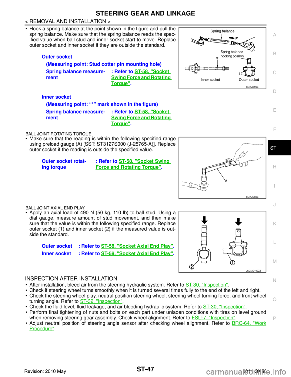
Hook a spring balance at the point shown in the figure and pull the spring balance. Make sure that the spring balance reads the spec-
ified value when ball stud and inner socket start to move. Replace
outer socket and inner socket if they are outside the standard.
BALL JOINT ROTATING TORQUE
Make sure that the reading is within the following specified rangeusing preload gauge (A) [SST: ST3127S000 (J-25765-A)]. Replace
outer socket if the reading is outside the specified value.
BALL JOINT AXIAL END PLAY
Apply an axial load of 490 N (50 kg, 110 lb) to ball stud. Using adial gauge, measure amount of stud movement, and then make
sure that the value is within the following specified range. Replace
outer socket (1) and inner socket (2) if the measured value is out-
side the standard.
INSPECTION AFTER INSTALLATION
After installation, bleed air from the steering hydraulic system. Refer to ST-30, "Inspection".
Check if steering wheel turns smoothly when it is turned several times fully to the end of the left and right.
Check the steering wheel play, neutral position steeri ng wheel, steering wheel turning force, and front wheel
turning angle. Refer to ST-32, "
Inspection".
Check the fluid level, fluid leakage, and air bleeding hydraulic system. Refer to ST-30, "
Inspection".
Perform final tightening of nuts and bolts on each part under unladen conditions with tires on level ground when removing steering gear assembly. Check wheel alignment. Refer to FSU-7, "
Inspection".
Adjust neutral position of steering angle sensor after checking wheel alignment. Refer to BRC-64, "
Work
Procedure".
Outer socket
(Measuring point: Stud cotter pin mounting hole)
Spring balance measure-
ment : Refer to
ST-58, "
Socket
Swing Force and Rotating
To r q u e".
Inner socket (Measuring point: “*” mark shown in the figure)
Spring balance measure-
ment : Refer to
ST-58, "
Socket
Swing Force and Rotating
To r q u e".
Outer socket rotat-
ing torque : Refer to
ST-58, "
Socket Swing
Force and Rotating Torque".
SGIA0896E
SGIA1382E
Outer socket : Refer to ST-58, "Socket Axial End Play".
Inner socket : Refer to ST-58, "
Socket Axial End Play".
JSGIA0109ZZ
Revision: 2010 May2011 QX56