2011 INFINITI QX56 length
[x] Cancel search: lengthPage 2950 of 5598
FSU-8
< PERIODIC MAINTENANCE >
WHEEL ALIGNMENT
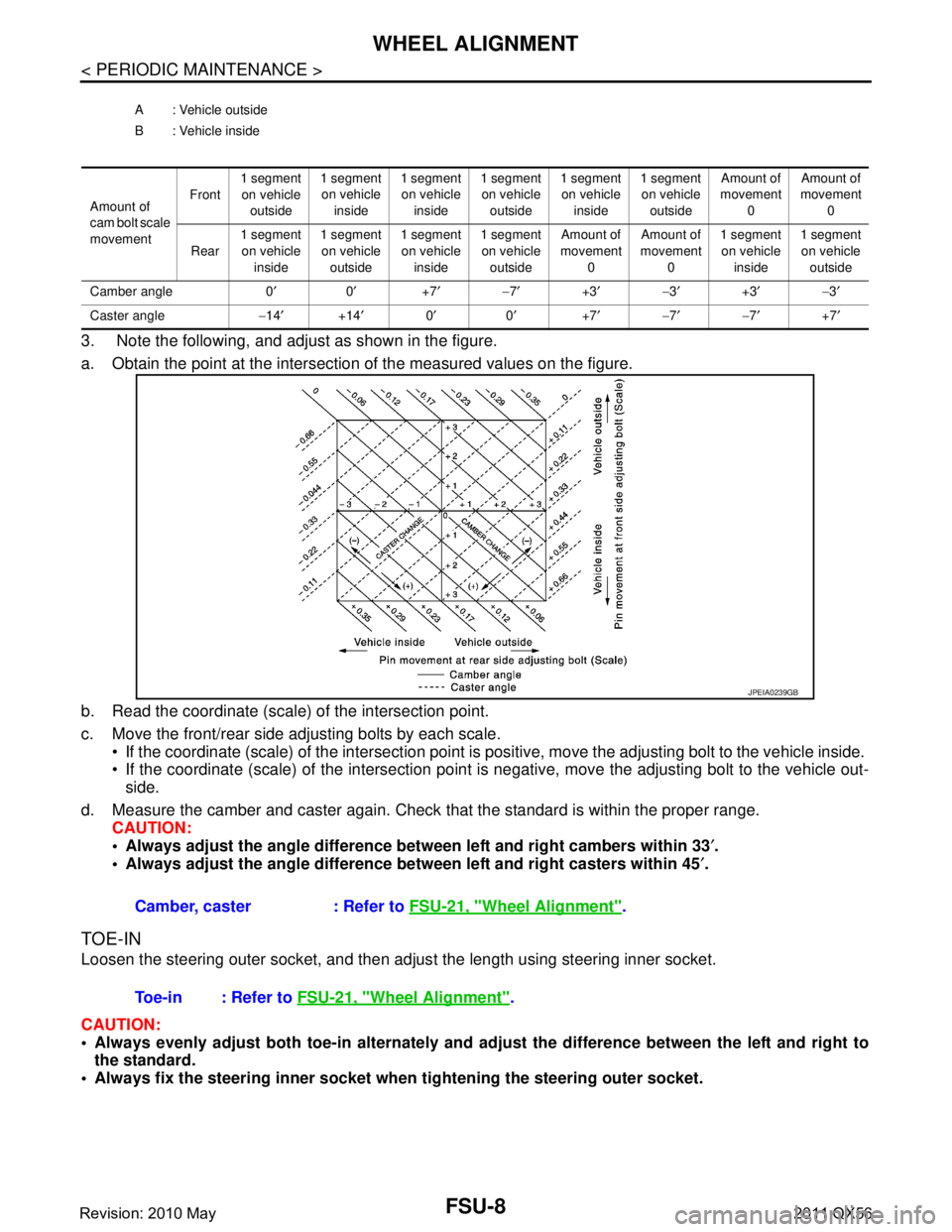
3. Note the following, and adjust as shown in the figure.
a. Obtain the point at the intersection of the measured values on the figure.
b. Read the coordinate (scale) of the intersection point.
c. Move the front/rear side adjusting bolts by each scale. If the coordinate (scale) of the intersection point is positive, move the adjusting bolt to the vehicle inside.
If the coordinate (scale) of the intersection point is negative, move the adjusting bolt to the vehicle out-
side.
d. Measure the camber and caster again. Check that the standard is within the proper range.
CAUTION:
Always adjust the angle difference betw een left and right cambers within 33′.
Always adjust the angle difference be tween left and right casters within 45′.
TOE-IN
Loosen the steering outer socket, and then adjus t the length using steering inner socket.
CAUTION:
Always evenly adjust both toe-in alternately and adjust the difference between the left and right to
the standard.
Always fix the steering inner socket when tightening the steering outer socket.
A : Vehicle outside
B : Vehicle inside
Amount of
cam bolt scale
movement Front
1 segment
on vehicle outside 1 segment
on vehicle inside 1 segment
on vehicle inside 1 segment
on vehicle outside 1 segment
on vehicle inside 1 segment
on vehicle outside Amount of
movement 0 Amount of
movement 0
Rear 1 segment
on vehicle inside 1 segment
on vehicle outside 1 segment
on vehicle inside 1 segment
on vehicle outside Amount of
movement 0 Amount of
movement 0 1 segment
on vehicle inside 1 segment
on vehicle outside
Camber angle 0 ′0′ +7′− 7′ +3′− 3′ +3′− 3′
Caster angle −14 ′ +14′ 0′ 0′ +7′− 7′− 7′ +7′
Camber, caster : Refer to FSU-21, "Wheel Alignment".
JPEIA0239GB
Toe-in : Refer to FSU-21, "Wheel Alignment".
Revision: 2010 May2011 QX56
Page 2989 of 5598
IDENTIFICATION INFORMATIONGI-25
< VEHICLE INFORMATION >
C
DE
F
G H
I
J
K L
M B
GI
N
O P
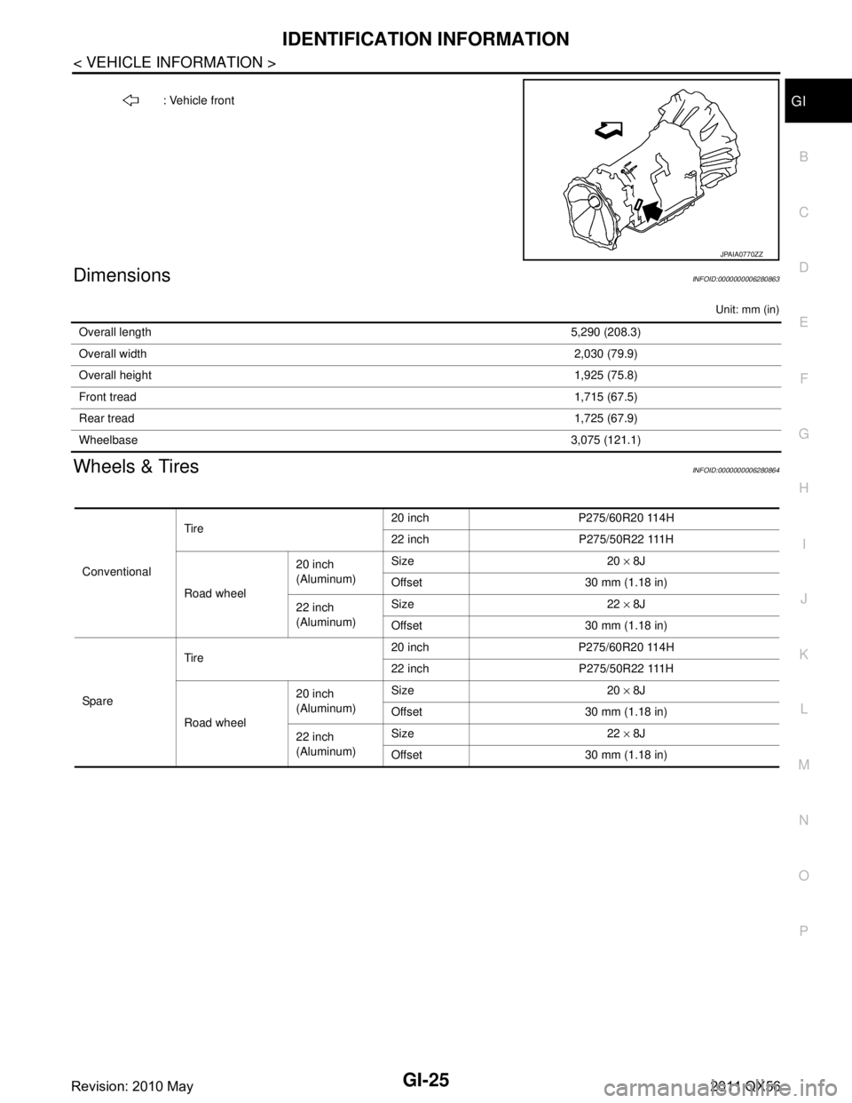
DimensionsINFOID:0000000006280863
Unit: mm (in)
Wheels & TiresINFOID:0000000006280864
: Vehicle front
JPAIA0770ZZ
Overall length 5,290 (208.3)
Overall width 2,030 (79.9)
Overall height 1,925 (75.8)
Front tread 1,715 (67.5)
Rear tread 1,725 (67.9)
Wheelbase 3,075 (121.1)
ConventionalTire
20 inch P275/60R20 114H
22 inch P275/50R22 111H
Road wheel 20 inch
(Aluminum)
Size 20
× 8J
Offset 30 mm (1.18 in)
22 inch
(Aluminum) Size 22
× 8J
Offset 30 mm (1.18 in)
Spare Tire
20 inch P275/60R20 114H
22 inch P275/50R22 111H
Road wheel 20 inch
(Aluminum)
Size 20
× 8J
Offset 30 mm (1.18 in)
22 inch
(Aluminum) Size 22
× 8J
Offset 30 mm (1.18 in)
Revision: 2010 May2011 QX56
Page 2994 of 5598
GI-30
< PRECAUTION >
PRECAUTIONS
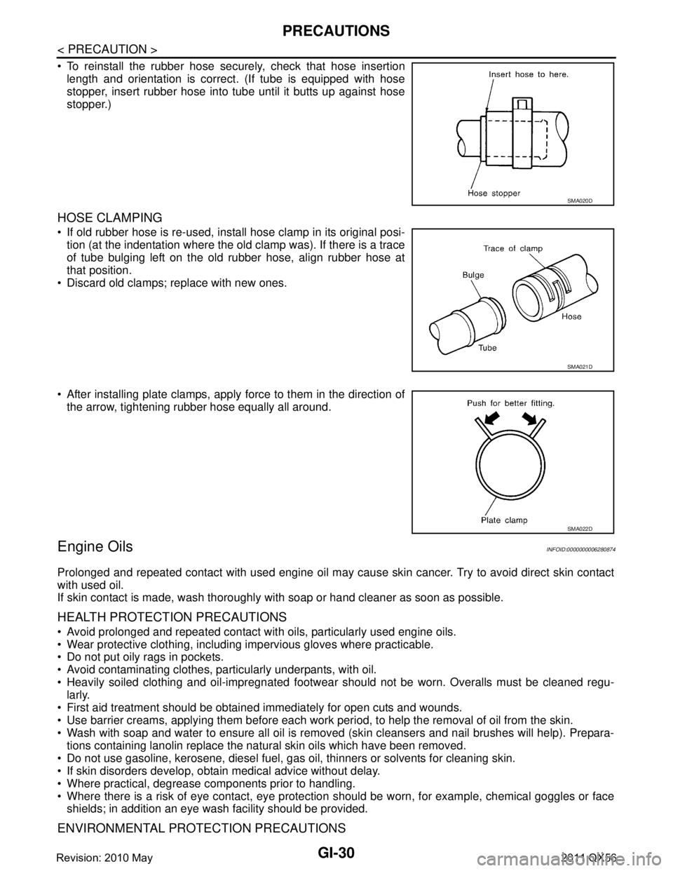
To reinstall the rubber hose securely, check that hose insertionlength and orientation is correct. (If tube is equipped with hose
stopper, insert rubber hose into tube until it butts up against hose
stopper.)
HOSE CLAMPING
If old rubber hose is re-used, install hose clamp in its original posi-tion (at the indentation where the old clamp was). If there is a trace
of tube bulging left on the old rubber hose, align rubber hose at
that position.
Discard old clamps; replace with new ones.
After installing plate clamps, apply force to them in the direction of the arrow, tightening rubber hose equally all around.
Engine OilsINFOID:0000000006280874
Prolonged and repeated contact with used engine oil may cause skin cancer. Try to avoid direct skin contact
with used oil.
If skin contact is made, wash thoroughly with soap or hand cleaner as soon as possible.
HEALTH PROTECTION PRECAUTIONS
Avoid prolonged and repeated contact with oils, particularly used engine oils.
Wear protective clothing, including impervious gloves where practicable.
Do not put oily rags in pockets.
Avoid contaminating clothes, pa rticularly underpants, with oil.
Heavily soiled clothing and oil-impregnated footwear should not be worn. Overalls must be cleaned regu-
larly.
First aid treatment should be obtained immediately for open cuts and wounds.
Use barrier creams, applying them before each work period, to help the removal of oil from the skin.
Wash with soap and water to ensure all oil is removed (skin cleansers and nail brushes will help). Prepara-
tions containing lanolin replace the natural skin oils which have been removed.
Do not use gasoline, kerosene, diesel fuel, gas oil, thinners or solvents for cleaning skin.
If skin disorders develop, obtain medical advice without delay.
Where practical, degrease components prior to handling.
Where there is a risk of eye contact, eye protection should be worn, for example, chemical goggles or face
shields; in addition an eye wash facility should be provided.
ENVIRONMENTAL PROTECTION PRECAUTIONS
SMA020D
SMA021D
SMA022D
Revision: 2010 May2011 QX56
Page 4210 of 5598
RAX-14
< REMOVAL AND INSTALLATION >
REAR DRIVE SHAFT
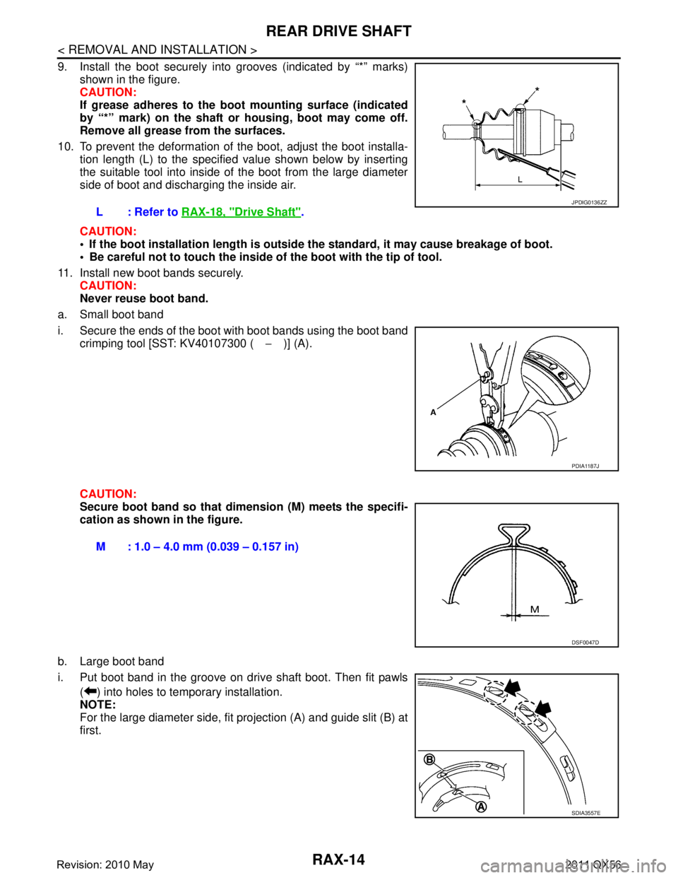
9. Install the boot securely into grooves (indicated by “*” marks)shown in the figure.
CAUTION:
If grease adheres to the boot mounting surface (indicated
by “*” mark) on the shaft or housing, boot may come off.
Remove all grease from the surfaces.
10. To prevent the deformation of the boot, adjust the boot installa- tion length (L) to the specified value shown below by inserting
the suitable tool into inside of the boot from the large diameter
side of boot and discharging the inside air.
CAUTION:
If the boot installation length is outsid e the standard, it may cause breakage of boot.
Be careful not to touch the inside of the boot with the tip of tool.
11. Install new boot bands securely. CAUTION:
Never reuse boot band.
a. Small boot band
i. Secure the ends of the boot with boot bands using the boot band crimping tool [SST: KV40107300 ( −)] (A).
CAUTION:
Secure boot band so that dimension (M) meets the specifi-
cation as shown in the figure.
b. Large boot band
i. Put boot band in the groove on drive shaft boot. Then fit pawls ( ) into holes to temporary installation.
NOTE:
For the large diameter side, fit projection (A) and guide slit (B) at
first.L: Refer to
RAX-18, "
Drive Shaft".
JPDIG0136ZZ
PDIA1187J
M : 1.0 – 4.0 mm (0.039 – 0.157 in)
DSF0047D
SDIA3557E
Revision: 2010 May2011 QX56
Page 4212 of 5598
RAX-16
< REMOVAL AND INSTALLATION >
REAR DRIVE SHAFT
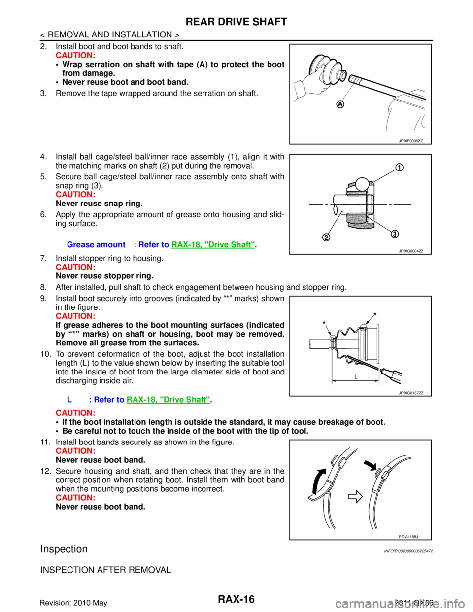
2. Install boot and boot bands to shaft.CAUTION:
Wrap serration on shaft with tape (A) to protect the bootfrom damage.
Never reuse boot and boot band.
3. Remove the tape wrapped around the serration on shaft.
4. Install ball cage/steel ball/inner race assembly (1), align it with the matching marks on shaft (2) put during the removal.
5. Secure ball cage/steel ball/inner race assembly onto shaft with snap ring (3).
CAUTION:
Never reuse snap ring.
6. Apply the appropriate amount of grease onto housing and slid- ing surface.
7. Install stopper ring to housing. CAUTION:
Never reuse stopper ring.
8. After installed, pull shaft to check engagement between housing and stopper ring.
9. Install boot securely into grooves (indicated by “*” marks) shown in the figure.
CAUTION:
If grease adheres to the boot mounting surfaces (indicated
by “*” marks) on shaft or housing, boot may be removed.
Remove all grease from the surfaces.
10. To prevent deformation of the boot, adjust the boot installation
length (L) to the value shown below by inserting the suitable tool
into the inside of boot from the large diameter side of boot and
discharging inside air.
CAUTION:
If the boot installation length is outsid e the standard, it may cause breakage of boot.
Be careful not to touch the inside of the boot with the tip of tool.
11. Install boot bands securely as shown in the figure. CAUTION:
Never reuse boot band.
12. Secure housing and shaft, and then check that they are in the correct position when rotating boot. Install them with boot band
when the mounting positi ons become incorrect.
CAUTION:
Never reuse boot band.
InspectionINFOID:0000000006225472
INSPECTION AFTER REMOVAL
JPDIF0009ZZ
Grease amount : Refer to RAX-18, "Drive Shaft".
L: Refer to RAX-18, "
Drive Shaft".
JPDIG0004ZZ
JPDIG0137ZZ
PDIA1188J
Revision: 2010 May2011 QX56
Page 4214 of 5598

RAX-18
< SERVICE DATA AND SPECIFICATIONS (SDS)
SERVICE DATA AND SPECIFICATIONS (SDS)
SERVICE DATA AND SPECIFICATIONS (SDS)
SERVICE DATA AND SPECIFICATIONS (SDS)
Wheel Hub and Bearing AssemblyINFOID:0000000006225473
Drive ShaftINFOID:0000000006225474
Item Standard
Axial end play 0.05 mm (0.002 in) or less
ItemStandard
Wheel side Final drive side
Grease quantity 145 – 165 g (5.11 – 5.82 oz) 175 – 195 g (6.17 – 6.88 oz)
Boots installed length 134.5 mm (5.30 in) 147.9 mm (5.82 in)
Revision: 2010 May2011 QX56
Page 4279 of 5598
SB-4
< REMOVAL AND INSTALLATION >
FRONT SEAT BELT
REMOVAL AND INSTALLATION
FRONT SEAT BELT
SEAT BELT RETRACTOR
SEAT BELT RETRACTOR : InspectionINFOID:0000000006217615
AFTER A COLLISION
WARNING:
Inspect all seat belt assemblies including retractors and attached hardware after any collision.
NISSAN/INFINITI recommends that all seat belt assemblies in use during a collision be replaced
unless the collision was minor and th e belts show no damage and continue to operate properly. Fail-
ure to do so could result in seri ous personal injury in an accident. Seat belt assemblies not in use dur-
ing a collision should also be re placed if either damage or improper operation was noted. Seat belt
pre-tensioners should be replaced even if the seat be lts were not in use during a frontal collision in
which the air bags were deployed.
Replace any seat belt assembly (including anchor bolts) if:
The seat belt is in use at the time of a collision (e xcept for minor collisions and the belts, retractors and buck-
les show no damage and continue to operate properly).
The seat belt is damaged in an accident (i.e. to rn webbing, bent retractor or guide, etc.).
The seat belt attaching point is damaged in an accident . Inspect the seat belt attaching area for damage or
distortion and repair if necessary before installing a new seat belt assembly.
Anchor bolts are deformed or worn out.
The seat belt pre-tensioners must be replaced even if t he seat belts were not in use during the collision in
which the air bags were deployed.
PRELIMINARY CHECKS
1. Check the seat belt warning lamp for proper operation as per the following:
a. Turn ignition switch ON. The seat belt warning lamp should illuminate.
b. Fasten driver seat belt. The seat belt warning lamp should turn OFF.
2. If the air bag warning lamp is blinking, perform self-diagnosis with CONSULT-III and air bag warning lamp. Refer to SRC-14, "
Description".
3. Check that the seat belt retractor, s eat belt anchor and buckle bolts are tightened firmly.
4. Check the shoulder seat belt guide and shoulder belt height adjuster for front seats. Check that guide
swivels freely and that webbing lays flat and does not bind in guide. Check that height adjuster operates
properly and holds securely.
5. Check retractor operation:
a. Fully extend the seat belt webbing and c heck for twists, tears or other damage.
b. Allow the seat belt to retract. Check that webbing retu rns smoothly and completely into the retractor. If the
seat belt does not return smoothly, wipe the inside of the loops with a clean paper cloth. Dirt build-up in the
loops of the upper anchors can cause the seat belts to retract slowly.
c. Fasten the seat belt. Check that seat belt returns sm oothly and completely to the retractor. If the webbing
does not return smoothly, the cause may be an accumulation of dust or dirt. Use the “SEAT BELT TAPE
SET” and perform the following steps.
Inspect the front seat belt through-anchor
1. Pull the seat belt out to a length of 500 mm (19.69 in) or more.
2. Fix the seat belt at the center pillar webbing opening with a clip or other device.
3. Pass a thin wire through the through-anchor webbing opening. Hold both ends of the wire and pull it tightly while moving it up and down several times along the webbing opening surface to remove dirt
stuck there.
4. Any dirt that cannot be removed with the wir e can be removed by cleaning the opening with a clean
cloth.
5. Apply tape at the point where the webbi ng contacts the through-anchor webbing opening.
NOTE:
Apply the tape so that there is no slack or wrinkling.
6. Remove the clip fixing the seat belt and check that the webbing returns smoothly.
6. Repeat steps above if necessary to check the other seat belts.
Revision: 2010 May2011 QX56
Page 4280 of 5598
FRONT SEAT BELTSB-5
< REMOVAL AND INSTALLATION >
C
DE
F
G
I
J
K L
M A
B
SB
N
O P
SEAT BELT RETRACTOR ON-VEHICLE CHECK
Emergency Locking Retractors (ELR) and Automatic Locking Retractors (ALR)
NOTE:
All seat belt retractors are Emergency Locking Retr actors (ELR) type. In an emergency (sudden stop) the
retractor will lock and prevent the webbing from extendi ng any further. All 3-point type seat belt retractors
except the driver seat belt also have an Automati c Locking Retractors (ALR) mode. The ALR mode (also
called child restraint mode) is used when installing child seats. The ALR mode is activated when the seat belt
is fully extended. When the webbing is then retracted part ially, the ALR mode automatically locks the seat belt
in a specific position so the webbi ng cannot be extended any further. To c ancel the ALR mode, allow the seat
belt to fully wind back into the retractor.
Check the seat belt retractors with the following test(s ) to determine if a retractor assembly is operating prop-
erly.
ELR Function Stationary Check
Grasp the shoulder webbing and pull forward quickly. The retractor should lock and prevent the belt from
extending further.
ALR Function Stationary Check
1. Pull out the entire length of seat bel t from retractor until a click is heard.
2. Retract the webbing partially. A clicking noise should be heard as the webbing retracts indicating that the
retractor is in the Automatic Locking Retractors (ALR) mode.
3. Grasp the seat belt and try to pull out the retractor. The webbing must lock and not extend any further. If it
does not operate normally, replace the retractor assembly.
4. Allow the entire length of the webbing to retract to cancel the automatic locking mode.
ELR Function Moving Check
WARNING:
Perform the following test in a safe, open area clear of other vehicles and obstructions (for example, a
large, empty parking lot). Road surface must be p aved and dry. Never perform the following test on
wet or gravel roads or on public streets and highways. This could result in an accident and serious
personal injury. The driver and passenger must be prepared to brace themselves in the event that the
retractor does not lock.
1. Fasten driver seat belt. Buckle a passenger into the seat for the belt that is to be tested.
2. Proceed to the designated safe area.
3. Drive the vehicle at approximately 16 km/h ( 10 MPH). Notify any passengers of a pending sudden stop
and the driver and passenger must be prepared to brac e themselves in the event that the retractor does
not lock. Apply brakes firmly and make a very hard stop.
During stopping, seat belts should lock and not be extended. If the seat belt retractor assembly does not lock,
perform the retractor off-vehicle check.
SEAT BELT RETRACTOR OFF-VEHICLE CHECK
1. Remove the front seat belt retractor. Refer to SB-6, "SEAT BELT RETRACTOR : Removal and Installa-
tion".
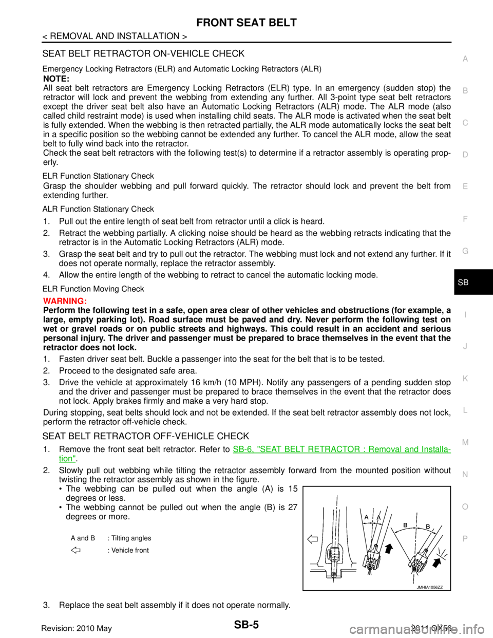
2. Slowly pull out webbing while tilting the retracto r assembly forward from the mounted position without
twisting the retractor assembly as shown in the figure.
The webbing can be pulled out when the angle (A) is 15
degrees or less.
The webbing cannot be pulled out when the angle (B) is 27
degrees or more.
3. Replace the seat belt assembly if it does not operate normally.
A and B : Tilting angles : Vehicle front
JMHIA1056ZZ
Revision: 2010 May2011 QX56