2011 INFINITI QX56 length
[x] Cancel search: lengthPage 5033 of 5598

ST-46
< REMOVAL AND INSTALLATION >
STEERING GEAR AND LINKAGE
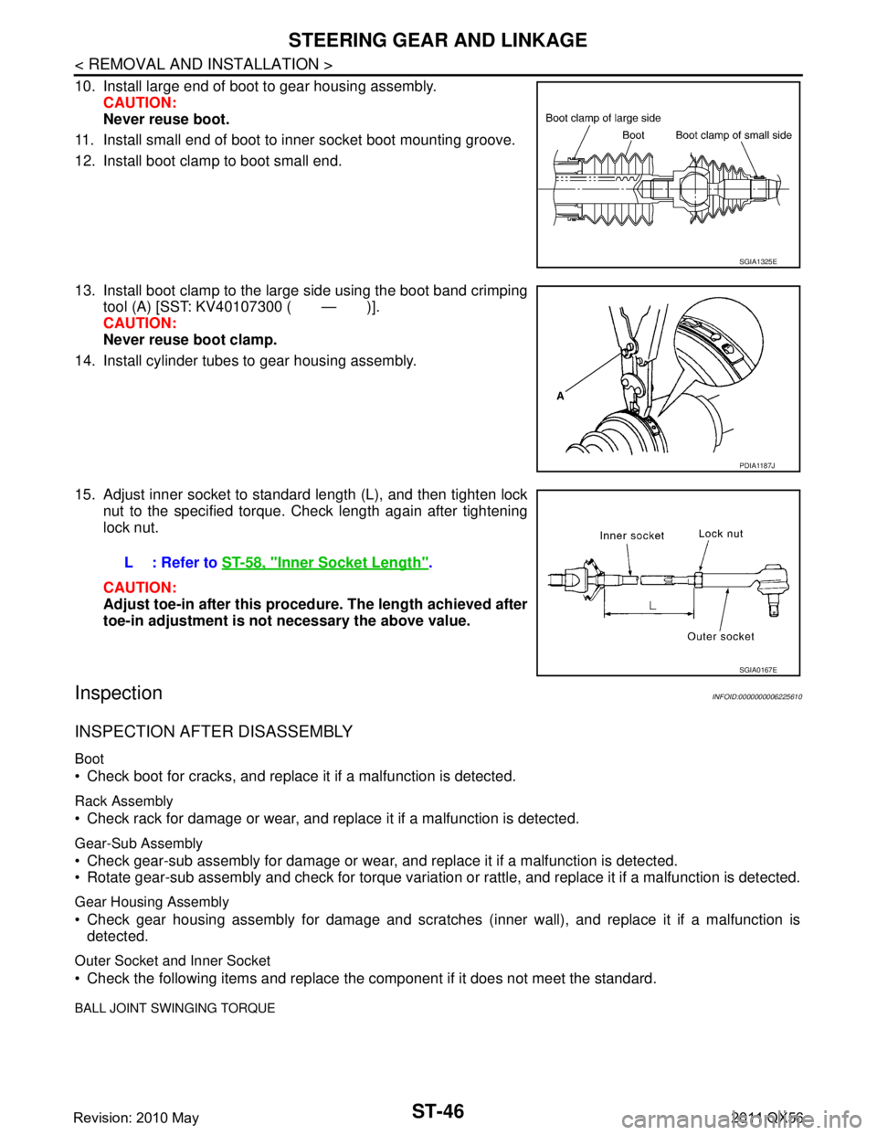
10. Install large end of boot to gear housing assembly.CAUTION:
Never reuse boot.
11. Install small end of boot to inner socket boot mounting groove.
12. Install boot clamp to boot small end.
13. Install boot clamp to the large side using the boot band crimping tool (A) [SST: KV40107300 ( — )].
CAUTION:
Never reuse boot clamp.
14. Install cylinder tubes to gear housing assembly.
15. Adjust inner socket to standard length (L), and then tighten lock nut to the specified torque. Check length again after tightening
lock nut.
CAUTION:
Adjust toe-in after this proced ure. The length achieved after
toe-in adjustment is not necessary the above value.
InspectionINFOID:0000000006225610
INSPECTION AFTER DISASSEMBLY
Boot
Check boot for cracks, and replace it if a malfunction is detected.
Rack Assembly
Check rack for damage or wear, and replace it if a malfunction is detected.
Gear-Sub Assembly
Check gear-sub assembly for damage or wear, and replace it if a malfunction is detected.
Rotate gear-sub assembly and check for torque variation or rattle, and replace it if a malfunction is detected.
Gear Housing Assembly
Check gear housing assembly for damage and scratches (inner wall), and replace it if a malfunction is
detected.
Outer Socket and Inner Socket
Check the following items and replace the component if it does not meet the standard.
BALL JOINT SWINGING TORQUE
SGIA1325E
PDIA1187J
L : Refer to ST-58, "Inner Socket Length".
SGIA0167E
Revision: 2010 May2011 QX56
Page 5044 of 5598

SERVICE DATA AND SPECIFICATIONS (SDS)
ST-57
< SERVICE DATA AND SPECIFICATIONS (SDS)
C
D E
F
H I
J
K L
M A
B
ST
N
O P
SERVICE DATA AND SPECIFICATIONS (SDS)
SERVICE DATA AND SPECIFICATIONS (SDS)
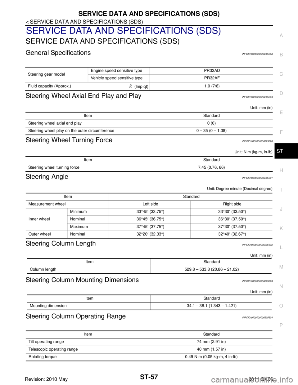
General SpecificationsINFOID:0000000006225618
Steering Wheel Axial End Play and PlayINFOID:0000000006225619
Unit: mm (in)
Steering Wheel Turning ForceINFOID:0000000006225620
Unit: N·m (kg-m, in-lb)
Steering AngleINFOID:0000000006225621
Unit: Degree minute (Decimal degree)
Steering Column LengthINFOID:0000000006225622
Unit: mm (in)
Steering Column Mounting DimensionsINFOID:0000000006225623
Unit: mm (in)
Steering Column Operating RangeINFOID:0000000006225624
Steering gear model Engine speed sensitive type PR32AD
Vehicle speed sensitive type PR32AF
Fluid capacity (Approx.) (lmp qt)1.0 (7/8)
Item Standard
Steering wheel axial end play 0 (0)
Steering wheel play on the outer circumference 0 – 35 (0 – 1.38)
Item Standard
Steering wheel turning force 7.45 (0.76, 66)
Item Standard
Measurement wheel Left side Right side
Inner wheel Minimum 33
°45 ′ (33.75 °)33 °30 ′ (33.50 °)
Nominal 36 °45 ′ (36.75 °)36 °30 ′ (37.50 °)
Maximum 37 °45 ′ (37.75 °)37 °30 ′ (37.50 °)
Outer wheel Nominal 32 °20 ′ (32.33 °)32 °40 ′ (32.67 °)
Item Standard
Column length 529.8 – 533.8 (20.86 – 21.02)
Item Standard
Mounting dimension 34.1 – 36.1 (1.343 – 1.421)
Item Standard
Tilt operating range 74 mm (2.91 in)
Telescopic operating range 40 mm (1.57 in)
Rotating torque 0.49 N· m (0.05 kg-m, 4 in-lb)
Revision: 2010 May2011 QX56
Page 5045 of 5598

ST-58
< SERVICE DATA AND SPECIFICATIONS (SDS)
SERVICE DATA AND SPECIFICATIONS (SDS)
Steering Shaft Sliding Range
INFOID:0000000006225625
Unit: mm (in)
Rack Sliding ForceINFOID:0000000006225626
Unit: N (kg, lb)
Rack StrokeINFOID:0000000006225627
Unit: mm (in)
Socket Swing Force and Rotating TorqueINFOID:0000000006225628
SWING FORCE
Unit: N (kg, lb)
ROTATING TORQUE
Unit: N·m (kg-m, in-lb)
Socket Axial End PlayINFOID:0000000006225629
Unit: mm (in)
Inner Socket LengthINFOID:0000000006225630
Unit: mm (in)
Relief Oil PressureINFOID:0000000006225631
Unit: kPa (bar, kg/cm2, psi)
Item Standard
Sliding range 47 (1.85)
Steering shaft length (extended position) 393 (15.47) or less
Steering shaft runout 1.5 (0.059) or less
Item Standard
Rack sliding force 249.6 – 308.4 (25.5 – 31.4, 56.2 – 69.3)
Item Standard
Rack neutral position, dimension 83.5 (3.287)
Item Spring balance
Outer socket 10.0 – 36.7 (1.02 – 3.74, 2.25 – 8.25)
Inner socket 19.4 – 32.3 (1.98 – 3.29, 4.37 – 7.26)
Item Standard
Outer socket 0.3 – 2.9 (0.03 – 0.3, 2.7 – 26)
Item Standard
Outer socket 0.5 (0.02) or less
Inner socket 0.2 (0.008) or less
Item Standard
Rack neutral position, dimension 110.8 (4.36)
Item Standard
Relief oil pressure 9,500 – 10,300 (95 – 103, 96.9 – 105.1, 1,378 – 1,494)
Revision: 2010 May2011 QX56
Page 5088 of 5598

STR-20
< SERVICE DATA AND SPECIFICATIONS (SDS)
SERVICE DATA AND SPECIFICATIONS (SDS)
SERVICE DATA AND SPECIFICATIONS (SDS)
SERVICE DATA AND SPECIFICATIONS (SDS)
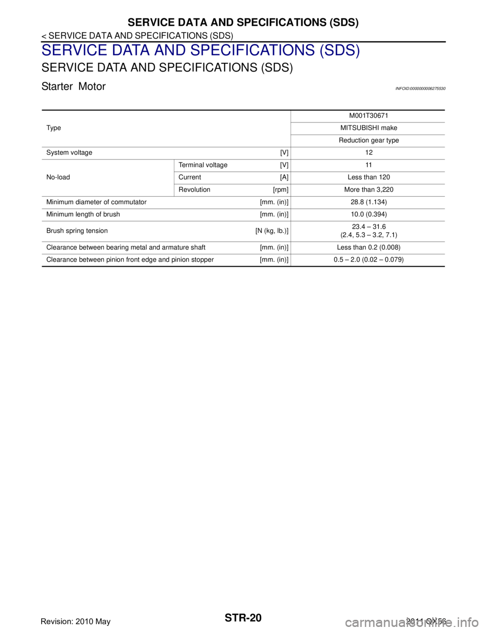
Starter MotorINFOID:0000000006275530
Ty p eM001T30671
MITSUBISHI make
Reduction gear type
System voltage [V] 12
No-load Terminal voltage [V] 11
Current [A] Less than 120
Revolution [rpm] More than 3,220
Minimum diameter of commutator [mm. (in)] 28.8 (1.134)
Minimum length of brush [mm. (in)] 10.0 (0.394)
Brush spring tension [N (kg, lb.)] 23.4 – 31.6
(2.4, 5.3 – 3.2, 7.1)
Clearance between bearing metal and armature shaft [mm. (in)] Less than 0.2 (0.008)
Clearance between pinion front edge and pinion stopper [mm. (in)] 0.5 – 2.0 (0.02 – 0.079)
Revision: 2010 May2011 QX56
Page 5272 of 5598
![INFINITI QX56 2011 Factory Service Manual
TM-184
< REMOVAL AND INSTALLATION >[7AT: RE7R01B]
CONTROL VALVE & TCM
9. Remove bolts and clip (1) from the control valve & TCM.
*: Reamer bolt
10. Remove the control valve & TCM from transmission ca INFINITI QX56 2011 Factory Service Manual
TM-184
< REMOVAL AND INSTALLATION >[7AT: RE7R01B]
CONTROL VALVE & TCM
9. Remove bolts and clip (1) from the control valve & TCM.
*: Reamer bolt
10. Remove the control valve & TCM from transmission ca](/manual-img/42/57033/w960_57033-5271.png)
TM-184
< REMOVAL AND INSTALLATION >[7AT: RE7R01B]
CONTROL VALVE & TCM
9. Remove bolts and clip (1) from the control valve & TCM.
*: Reamer bolt
10. Remove the control valve & TCM from transmission case.
CAUTION:
When removing, be careful wi th the manual valve (1) notch
and manual plate (2) height. Remove it vertically.
11. Remove joint connector (1) from the control valve & TCM using a flat-bladed screwdriver (A).
12. Disconnect TCM connector (A). CAUTION:
Be careful not to damage connector.
INSTALLATION
Note the following, and install in the reverse order of removal.
CAUTION:
Be careful not to damage connector when installing any connector.
Never reuse joint connector.
Apply ATF to O-ring of joint connector.
Never reuse drain plug and drain plug gasket. In addition, install new drain plug and drain plug gas-
ket after adjustment of A/T fluid filling.
Refer to the following when installing the control valve & TCM to transmission case.
: Vehicle front
Bolt symbol Length mm (in) Number of bolts A 43 (1.69) 3
B 40 (1.57) 2
C 54 (2.13) 6
D 50 (1.97) 2
E* 50 (1.97) 1
JPDIA1105ZZ
JPDIA0012ZZ
JSDIA1718ZZ
JSDIA1813ZZ
Revision: 2010 May2011 QX56
Page 5273 of 5598
![INFINITI QX56 2011 Factory Service Manual
CONTROL VALVE & TCMTM-185
< REMOVAL AND INSTALLATION > [7AT: RE7R01B]
C
EF
G H
I
J
K L
M A
B
TM
N
O P
CAUTION:
Make sure that turbine revolution sensor securely installs input speed sensor holes (A INFINITI QX56 2011 Factory Service Manual
CONTROL VALVE & TCMTM-185
< REMOVAL AND INSTALLATION > [7AT: RE7R01B]
C
EF
G H
I
J
K L
M A
B
TM
N
O P
CAUTION:
Make sure that turbine revolution sensor securely installs input speed sensor holes (A](/manual-img/42/57033/w960_57033-5272.png)
CONTROL VALVE & TCMTM-185
< REMOVAL AND INSTALLATION > [7AT: RE7R01B]
C
EF
G H
I
J
K L
M A
B
TM
N
O P
CAUTION:
Make sure that turbine revolution sensor securely installs input speed sensor holes (A).
Hang down output speed senso r harness toward outside so
as not to disturb installation of the control valve & TCM.
Adjust A/T assembly harness connector of the control valve
& TCM to terminal hole of transmission case.
Assemble it so that manual valve (1) cutout is engaged with manual plate (2) projection.
- Install bolts and clip (1) to the control valve & TCM. Tighten bolt (E) to the specified torque before tightening the other than bolts.
*: Reamer bolt
Refer to the following when installing oil pan to transmission case.CAUTION:
Clean foreign materials (gear wear particles) that adhere on the inside of the oil pan and on the
magnet, and then assembly.
Completely remove all moisture, oil and old gasket, etc. from oil pan gasket mounting surface of
transmission case and oil pan.
Never reuse oil pan gasket and oil pan mounting bolts.
Install oil pan gasket in the di rection to align hole position.
- Tighten the oil pan mounting bolts to the specified torque in the numerical order as shown in the figure after temporarily tightening
them.
JPDIA1106ZZ
JPDIA0012ZZ
: Vehicle front
Bolt symbol Length mm (in) Number of bolts A 43 (1.69) 3
B 40 (1.57) 2
C 54 (2.13) 6
D 50 (1.97) 2
E* 50 (1.97) 1
: Vehicle front
JPDIA1105ZZ
JSDIA1592GB
Revision: 2010 May2011 QX56
Page 5295 of 5598
![INFINITI QX56 2011 Factory Service Manual
TRANSMISSION ASSEMBLYTM-207
< UNIT REMOVAL AND INSTALLATION > [7AT: RE7R01B]
C
EF
G H
I
J
K L
M A
B
TM
N
O P
When installing A/T assembly to the engine, be sure to check dimension “A” to ensure INFINITI QX56 2011 Factory Service Manual
TRANSMISSION ASSEMBLYTM-207
< UNIT REMOVAL AND INSTALLATION > [7AT: RE7R01B]
C
EF
G H
I
J
K L
M A
B
TM
N
O P
When installing A/T assembly to the engine, be sure to check dimension “A” to ensure](/manual-img/42/57033/w960_57033-5294.png)
TRANSMISSION ASSEMBLYTM-207
< UNIT REMOVAL AND INSTALLATION > [7AT: RE7R01B]
C
EF
G H
I
J
K L
M A
B
TM
N
O P
When installing A/T assembly to the engine, be sure to check dimension “A” to ensure it is within the reference value limit.
When installing A/T assembly to the engine, attach the fixing bolts in accordance with the following standard.
*: Tightening the bolt with bracket (and washer). Refer to TM-199, "2WD : Exploded View".
Align the positions of tightening bolts for drive plate with those of the torque converter, and temporarily
tighten the bolts. Then, tighten the bolts with the specified torque.
CAUTION:
When turning crankshaft, turn it clockwise as viewed from the front of the engine.
When tightening the tightening bolts for the torq ue converter after fixing the crankshaft pulley
bolts, be sure to confirm the tightening torque of the crankshaft pulley mounting bolts. Refer to
EM-62, "
Removal and Installation".
Rotate crankshaft several turns and check to be sure that A/T rotates freely without binding after
converter is installed to drive plate.
2WD : Inspection and AdjustmentINFOID:0000000006233265
INSPECTION AFTER INSTALLATION
Check A/T fluid leakage. Refer to TM-175, "Inspection".
Check A/T position after adjusting A/T position. Refer to TM-101, "
Inspection".
ADJUSTMENT AFTER INSTALLATION
Adjust A/T fluid level. Refer to TM-95, "Adjustment".
Adjust A/T position. Refer to TM-101, "
Adjustment".
Perform decel G sensor calibration when replacing A/T assembly. Refer to TM-91, "
Special Repair Require-
ment".
4WD
B: Scale
C : Straightedge
Dimension “A” : Refer to TM-297, "Torque Convert-
er".
JPDIA0042ZZ
Bolt symbol A
Insertion direction A/T assembly to engine
Number of bolts 9
Bolt length “L”
mm (in) 70 (2.76)
Tightening torque
N·m (kg-m, ft-lb) 113 (12, 83)
JSDIA1598ZZ
Revision: 2010 May2011 QX56
Page 5298 of 5598
![INFINITI QX56 2011 Factory Service Manual
TM-210
< UNIT REMOVAL AND INSTALLATION >[7AT: RE7R01B]
TRANSMISSION ASSEMBLY
When installing A/T assembly to the engine, attach the fixing bolts
in accordance with the following standard.
*: Tighte INFINITI QX56 2011 Factory Service Manual
TM-210
< UNIT REMOVAL AND INSTALLATION >[7AT: RE7R01B]
TRANSMISSION ASSEMBLY
When installing A/T assembly to the engine, attach the fixing bolts
in accordance with the following standard.
*: Tighte](/manual-img/42/57033/w960_57033-5297.png)
TM-210
< UNIT REMOVAL AND INSTALLATION >[7AT: RE7R01B]
TRANSMISSION ASSEMBLY
When installing A/T assembly to the engine, attach the fixing bolts
in accordance with the following standard.
*: Tightening the bolt with bracket (and washer). Refer to TM-200, "4WD : Exploded View".
Align the positions of tightening bolts for drive plate with those of the torque converter, and temporarily
tighten the bolts. Then, tighten the bolts with the specified torque.
CAUTION:
When turning crankshaft, turn it clockwi se as viewed from the front of the engine.
When tightening the tightening bolts for the torque converter after fixing the crankshaft pulley
bolts, be sure to confirm the tightening torque of the crankshaft pulley mounting bolts. Refer to
EM-62, "
Removal and Installation".
Rotate crankshaft several turns and check to be sure that A/T rotates freely without binding after
converter is installed to drive plate.
4WD : Inspection and AdjustmentINFOID:0000000006226912
INSPECTION AFTER INSTALLATION
Check A/T fluid leakage.
Check A/T position after adjusting A/T position. Refer to TM-101, "
Inspection".
ADJUSTMENT AFTER INSTALLATION
Adjust A/T fluid level. Refer to TM-95, "Adjustment".
Adjust A/T position. Refer to TM-101, "
Inspection".
Perform decel G sensor calibration w hen replacing A/T assembly. Refer to TM-91, "
Special Repair Require-
ment".
Bolt symbol A
Insertion direction A/T assembly to engine
Number of bolts 9
Bolt length “L”
mm (in) 70 (2.76)
Tightening torque
N·m (kg-m, ft-lb) 113 (12, 83)
JSDIA1598ZZ
Revision: 2010 May2011 QX56