2011 INFINITI QX56 length
[x] Cancel search: lengthPage 2061 of 5598
![INFINITI QX56 2011 Factory Service Manual
SYSTEMEC-37
< SYSTEM DESCRIPTION > [VK56VD]
C
D
E
F
G H
I
J
K L
M A
EC
NP
O
*1: This sensor is not used to control the engine system under normal conditions.
*2: ECM determines the start signal statu INFINITI QX56 2011 Factory Service Manual
SYSTEMEC-37
< SYSTEM DESCRIPTION > [VK56VD]
C
D
E
F
G H
I
J
K L
M A
EC
NP
O
*1: This sensor is not used to control the engine system under normal conditions.
*2: ECM determines the start signal statu](/manual-img/42/57033/w960_57033-2060.png)
SYSTEMEC-37
< SYSTEM DESCRIPTION > [VK56VD]
C
D
E
F
G H
I
J
K L
M A
EC
NP
O
*1: This sensor is not used to control the engine system under normal conditions.
*2: ECM determines the start signal status by the signals of engine speed and battery voltage.
SYSTEM DESCRIPTION
The adoption of the direct fuel injection method enables
more accurate adjustment of fuel injection quantity by
injecting atomized high-pressure fuel directly into the cylinder. This method allows high-powered engine, low
fuel consumption, and emissions-reduction.
The amount of fuel injected from the fuel injector is determined by the ECM. The ECM controls the length of
time the valve remains open (injection pulse duration). T he amount of fuel injected is a program value in the
ECM memory. The program value is preset by engi ne operating conditions. These conditions are determined
by input signals (for engine speed and intake air and fuel rail pressure) from the crankshaft position sensor,
camshaft position sensor, mass air flow sensor and the fuel rail pressure sensor.
VARIOUS FUEL INJECTION INCREASE/DECREASE COMPENSATION
In addition, the amount of fuel injected is compens ated to improve engine performance under various operat-
ing conditions as listed below.
When starting the engine
During acceleration
Hot-engine operation
When selector lever position is changed from N to D
High-load, high-speed operation
During deceleration
During high engine speed operation
FUEL INJECTION CONTROL
Stratified-charge Combustion
Stratified-charge combustion is a combustion method wh ich enables extremely lean combustion by injecting
fuel in the latter half of a compression process, coll ecting combustible air-fuel around the spark plug, and form-
ing fuel-free airspace around the mixture.
Right after a start with the engine cold, the catalyst warm-up is accelerated by stratified-charge combustion.
Homogeneous Combustion
Sensor Input signal to ECM ECM function Actuator
Crankshaft position sensor Engine speed*
2
Fuel injection
& mixture ratio
controlFuel injector
Camshaft position sensor Camshaft position
Mass air flow sensor Amount of intake air
Intake air temperature sensor Intake air temperature
Engine coolant temperature sensor Engine coolant temperature
Air fuel ratio (A/F) sensor 1 Density of oxygen in exhaust gas
Fuel rail pressure sensor Fuel rail pressure
Throttle position sensor Throttle position
Accelerator pedal position sensor Accelerator pedal position
TCM Gear position
Battery
Battery voltage*
2
Knock sensor Engine knocking condition
Power steering pressure sensor Power steering operation
Heated oxygen sensor 2*
1Density of oxygen in exhaust gas
ABS actuator and electric unit (control unit) VDC/TCS operation command
A/C auto amp. A/C ON signal
Combination meter Vehicle speed
Revision: 2010 May2011 QX56
Page 2086 of 5598
![INFINITI QX56 2011 Factory Service Manual
EC-62
< SYSTEM DESCRIPTION >[VK56VD]
DIAGNOSIS SYSTEM (ECM)
NOTE:
Wait until the same DTC (or 1st trip DTC)
appears to completely confirm all DTCs.
How to Read Self-diagnostic Results
The DTC and 1s INFINITI QX56 2011 Factory Service Manual
EC-62
< SYSTEM DESCRIPTION >[VK56VD]
DIAGNOSIS SYSTEM (ECM)
NOTE:
Wait until the same DTC (or 1st trip DTC)
appears to completely confirm all DTCs.
How to Read Self-diagnostic Results
The DTC and 1s](/manual-img/42/57033/w960_57033-2085.png)
EC-62
< SYSTEM DESCRIPTION >[VK56VD]
DIAGNOSIS SYSTEM (ECM)
NOTE:
Wait until the same DTC (or 1st trip DTC)
appears to completely confirm all DTCs.
How to Read Self-diagnostic Results
The DTC and 1st trip DTC are indicated by the number of blinks of the MIL as shown below.
The DTC and 1st trip DTC are displayed at the same time. If the MIL does not illuminate in diagnostic test
mode I (Malfunction warning), all displayed items are 1s t trip DTCs. If only one code is displayed when the MIL
illuminates in “malfunction warning” mode, it is a DTC; if two or more codes are displayed, they may be either
DTCs or 1st trip DTCs. DTC No. is same as that of 1st trip DTC. These unidentified codes can be identified by
using the CONSULT-III or GST. A DTC will be used as an example for how to read a code.
A particular trouble code can be identified by the number of four-digit numeral flashes per the following.
The length of time the 1,000th-digit numeral flashes on and off is 1.2 seconds consisting of an ON (0.6-sec-
onds) - OFF (0.6-seconds) cycle.
The 100th-digit numeral and lower digit numerals consis t of a 0.3-seconds ON and 0.3-seconds OFF cycle.
A change from one digit numeral to another occurs at an inte rval of 1.0-second OFF. In other words, the later
numeral appears on the display 1.3 seconds after the former numeral has disappeared.
A change from one trouble code to another occurs at an interval of 1.8-seconds OFF.
PBIB0092E
PBIB3005E
Number 0123456789ABCDEF
Flashes 10123456789111213141516
Revision: 2010 May2011 QX56
Page 2621 of 5598

OIL PAN (UPPER)EM-59
< REMOVAL AND INSTALLATION >
C
DE
F
G H
I
J
K L
M A
EM
NP
O
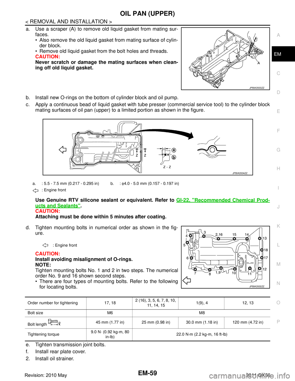
a. Use a scraper (A) to remove old liquid gasket from mating sur-
faces.
Also remove the old liquid gasket from mating surface of cylin-der block.
Remove old liquid gasket from the bolt holes and threads.
CAUTION:
Never scratch or damage th e mating surfaces when clean-
ing off old liquid gasket.
b. Install new O-rings on the bottom of cylinder block and oil pump.
c. Apply a continuous bead of liquid gasket with tube pre sser (commercial service tool) to the cylinder block
mating surfaces of oil pan (upper) to a limited portion as shown in the figure.
Use Genuine RTV silicone sealant or equivalent. Refer to GI-22, "
Recommended Chemical Prod-
ucts and Sealants".
CAUTION:
Attaching must be done with in 5 minutes after coating.
d. Tighten mounting bolts in numerical order as shown in the fig- ure.
CAUTION:
Install avoiding misal ignment of O-rings.
NOTE:
Tighten mounting bolts No. 1 and 2 in two steps. The numerical
order No. 9 and 16 shown second steps.
There are four types of mounting bolts. Refer to the following for locating bolts.
e. Tighten transmission joint bolts.
f. Install rear plate cover.
2. Install oil strainer.
JPBIA3503ZZ
a. : 5.5 - 7.5 mm (0.217 - 0.295 in) b. : φ4.0 - 5.0 mm (0.157 - 0.197 in)
: Engine front
JPBIA3504ZZ
: Engine front
JPBIA3502ZZ
Order number for tightening 17, 18 2 (16), 3, 5, 6, 7, 8, 10,
11, 14, 15 1(9), 4 12, 13
Bolt size M6 M8
Bolt length 45 mm (1.77 in) 25 mm (0.98 in) 30.0 mm (1.18 in) 120 mm (4.72 in)
Tightening torque 9.0 N· (0.92 kg-m, 80
in-lb) 22.0 N·m (2.2 kg-m, 16 ft-lb)
Revision: 2010 May2011 QX56
Page 2697 of 5598

SERVICE DATA AND SPECIFICATIONS (SDS)
EM-135
< SERVICE DATA AND SPECIFICATIONS (SDS)
C
D E
F
G H
I
J
K L
M A
EM
NP
O
Cylinder HeadINFOID:0000000006289594
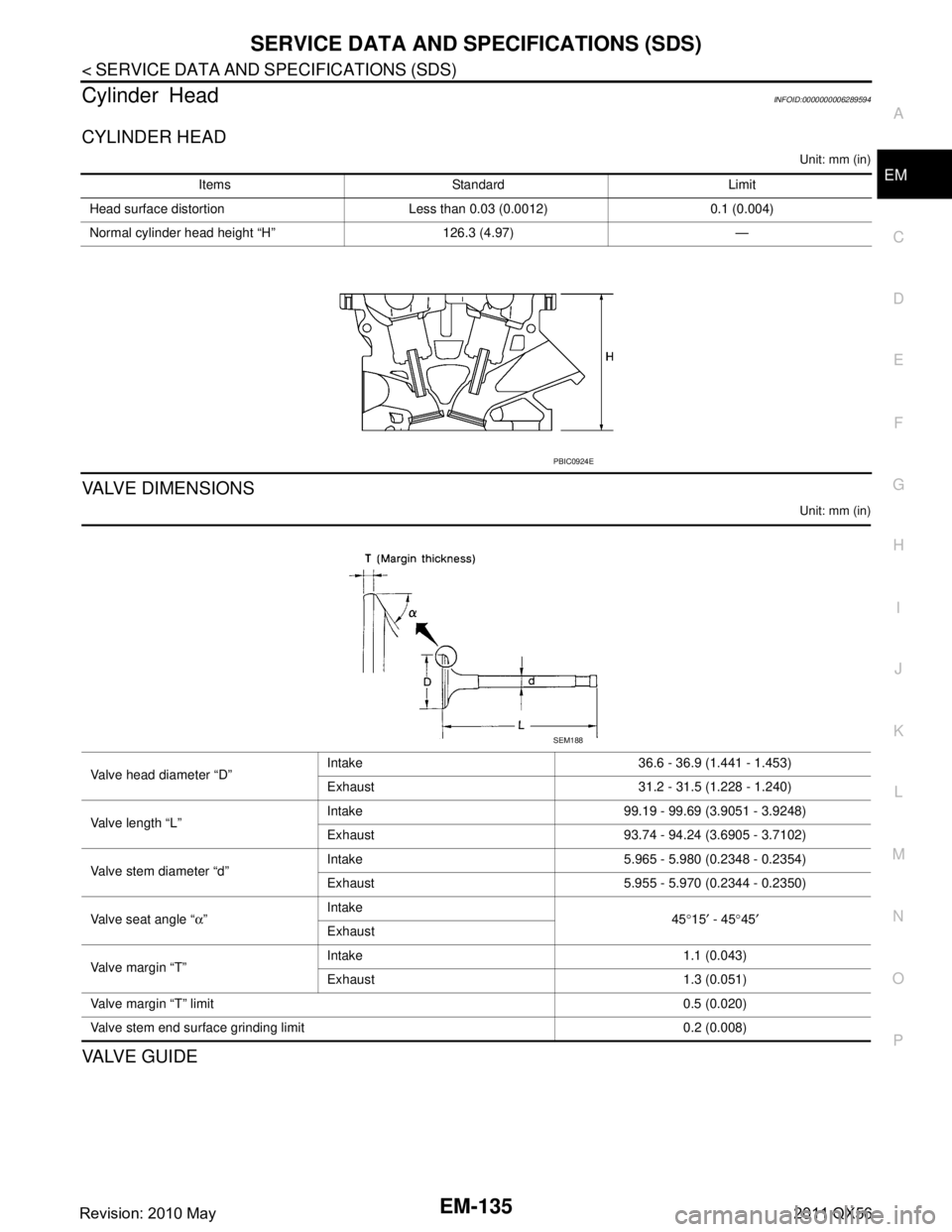
CYLINDER HEAD
Unit: mm (in)
VALVE DIMENSIONS
Unit: mm (in)
VA LV E G U I D E
Items Standard Limit
Head surface distortion Less than 0.03 (0.0012) 0.1 (0.004)
Normal cylinder head height “H” 126.3 (4.97) —
PBIC0924E
Valve head diameter “D” Intake 36.6 - 36.9 (1.441 - 1.453)
Exhaust 31.2 - 31.5 (1.228 - 1.240)
Valve length “L” Intake 99.19 - 99.69 (3.9051 - 3.9248)
Exhaust 93.74 - 94.24 (3.6905 - 3.7102)
Valve stem diameter “d” Intake 5.965 - 5.980 (0.2348 - 0.2354)
Exhaust 5.955 - 5.970 (0.2344 - 0.2350)
Valve seat angle “ α” Intake
45°15 ′ - 45 °45 ′
Exhaust
Valve margin “T” Intake 1.1 (0.043)
Exhaust 1.3 (0.051)
Valve margin “T” limit 0.5 (0.020)
Valve stem end surface grinding limit 0.2 (0.008)
SEM188
Revision: 2010 May2011 QX56
Page 2698 of 5598

EM-136
< SERVICE DATA AND SPECIFICATIONS (SDS)
SERVICE DATA AND SPECIFICATIONS (SDS)
Unit: mm (in)
*: Parts settings are for exhaust side only
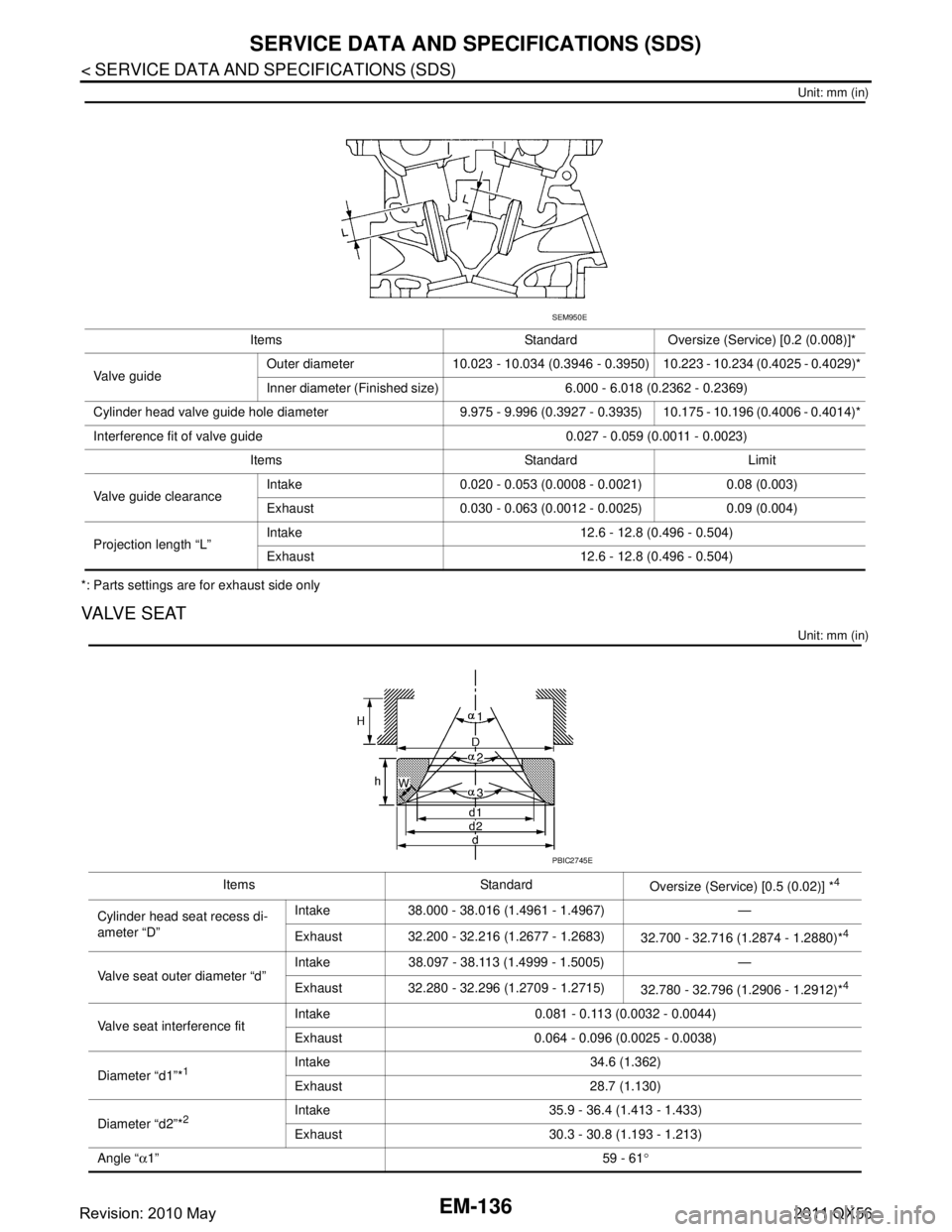
VALVE SEAT
Unit: mm (in)
Items Standard Oversize (Service) [0.2 (0.008)]*
Va l v e g u i d e Outer diameter 10.023 - 10.034 (0.3946 - 0.3950) 10.223 - 10.234 (0.4025 - 0.4029)*
Inner diameter (Finished size) 6.000 - 6.018 (0.2362 - 0.2369)
Cylinder head valve guide hole diameter 9.975 - 9.996 (0.3927 - 0.3935) 10.175 - 10.196 (0.4006 - 0.4014)*
Interference fit of valve guide 0.027 - 0.059 (0.0011 - 0.0023) Items Standard Limit
Valve guide clearance Intake 0.020 - 0.053 (0.0008 - 0.0021) 0.08 (0.003)
Exhaust 0.030 - 0.063 (0.0012 - 0.0025) 0.09 (0.004)
Projection length “L” Intake 12.6 - 12.8 (0.496 - 0.504)
Exhaust 12.6 - 12.8 (0.496 - 0.504)
SEM950E
Items Standard
Oversize (Service) [0.5 (0.02)] *4
Cylinder head seat recess di-
ameter “D”Intake 38.000 - 38.016 (1.4961 - 1.4967) —
Exhaust 32.200 - 32.216 (1.2677 - 1.2683)
32.700 - 32.716 (1.2874 - 1.2880)*
4
Valve seat outer diameter “d”Intake 38.097 - 38.113 (1.4999 - 1.5005) —
Exhaust 32.280 - 32.296 (1.2709 - 1.2715)
32.780 - 32.796 (1.2906 - 1.2912)*4
Valve seat interference fitIntake 0.081 - 0.113 (0.0032 - 0.0044)
Exhaust 0.064 - 0.096 (0.0025 - 0.0038)
Diameter “d1”*
1Intake 34.6 (1.362)
Exhaust 28.7 (1.130)
Diameter “d2”*
2Intake 35.9 - 36.4 (1.413 - 1.433)
Exhaust 30.3 - 30.8 (1.193 - 1.213)
Angle “ α1” 59 - 61°
PBIC2745E
Revision: 2010 May2011 QX56
Page 2925 of 5598
![INFINITI QX56 2011 Factory Service Manual
FRONT DRIVE SHAFTFAX-25
< REMOVAL AND INSTALLATION > [4WD]
C
EF
G H
I
J
K L
M A
B
FA X
N
O P
9. Install the boot securely into grooves (indicated by “*” marks) shown in the figure.
CAUTION:
If gr INFINITI QX56 2011 Factory Service Manual
FRONT DRIVE SHAFTFAX-25
< REMOVAL AND INSTALLATION > [4WD]
C
EF
G H
I
J
K L
M A
B
FA X
N
O P
9. Install the boot securely into grooves (indicated by “*” marks) shown in the figure.
CAUTION:
If gr](/manual-img/42/57033/w960_57033-2924.png)
FRONT DRIVE SHAFTFAX-25
< REMOVAL AND INSTALLATION > [4WD]
C
EF
G H
I
J
K L
M A
B
FA X
N
O P
9. Install the boot securely into grooves (indicated by “*” marks) shown in the figure.
CAUTION:
If grease adheres to the boot mounting surface (indicated
by “*” mark) on the shaft or housing, boot may come off.
Remove all grease from the surfaces.
10. To prevent the deformation of the boot, adjust the boot installa- tion length (L) to the specified value shown below by inserting
the suitable tool into inside of the boot from the large diameter
side of boot and discharging the inside air.
CAUTION:
If the boot installation length is outsid e the standard, it may cause breakage of boot.
Be careful not to touch the inside of the boot with the tip of tool.
11. Install new boot bands securely. CAUTION:
Never reuse boot band.
a. Small boot band
i. Secure the ends of the boot with boot bands using the boot band crimping tool [SST: KV40107300 ( −)] (A).
CAUTION:
Secure boot band so that dimension (M) meets the specifi-
cation as shown in the figure.
b. Large boot band
i. Put boot band in the groove on drive shaft boot. Then fit pawls ( ) into holes to temporary installation.
NOTE:
For the large diameter side, fit projection (A) and guide slit (B) at
first.L : Refer to
FAX-29, "
Drive Shaft".
JPDIG0136ZZ
PDIA1187J
M : 1.0 – 4.0 mm (0.039 – 0.157 in)
DSF0047D
SDIA3557E
Revision: 2010 May2011 QX56
Page 2927 of 5598
![INFINITI QX56 2011 Factory Service Manual
FRONT DRIVE SHAFTFAX-27
< REMOVAL AND INSTALLATION > [4WD]
C
EF
G H
I
J
K L
M A
B
FA X
N
O P
2. Install boot and boot bands to shaft. CAUTION:
Wrap serration on shaft with tape (A) to protect the b INFINITI QX56 2011 Factory Service Manual
FRONT DRIVE SHAFTFAX-27
< REMOVAL AND INSTALLATION > [4WD]
C
EF
G H
I
J
K L
M A
B
FA X
N
O P
2. Install boot and boot bands to shaft. CAUTION:
Wrap serration on shaft with tape (A) to protect the b](/manual-img/42/57033/w960_57033-2926.png)
FRONT DRIVE SHAFTFAX-27
< REMOVAL AND INSTALLATION > [4WD]
C
EF
G H
I
J
K L
M A
B
FA X
N
O P
2. Install boot and boot bands to shaft. CAUTION:
Wrap serration on shaft with tape (A) to protect the bootfrom damage.
Never reuse boot and boot band.
3. Remove the tape wrapped around the serration on shaft.
4. Install ball cage/steel ball/inner race assembly (1), align it with the matching marks on shaft (2) put during the removal.
5. Secure ball cage/steel ball/inner race assembly onto shaft with snap ring (3).
CAUTION:
Never reuse snap ring.
6. Apply the appropriate amount of grease onto housing and slid- ing surface.
7. Install housing to shaft.
8. Install stopper ring to housing. CAUTION:
Never reuse stopper ring.
9. After installed, pull shaft to check engagement between housing and stopper ring.
10. Install boot securely into grooves (indicated by “*” marks) shown in the figure.
CAUTION:
If grease adheres to the bo ot mounting surfaces (indicated
by “*” marks) on shaft or housing, boot may be removed.
Remove all grease from the surfaces.
11. To prevent deformation of the boot, adjust the boot installation
length (L) to the value shown below by inserting the suitable tool
into the inside of boot from the large diameter side of boot and
discharging inside air.
CAUTION:
If the boot installation length is outsid e the standard, it may cause breakage of boot.
Be careful not to touch the inside of the boot with the tip of tool.
12. Install boot bands securely as shown in the figure. CAUTION:
Never reuse boot band.
13. Secure housing and shaft, and then check that they are in the correct position when rotating boot. Install them with boot band
when the mounting positions become incorrect.
CAUTION:
Never reuse boot band.
14. Install dust shield to housing. CAUTION:
Never reuse dust shield.
15. Install circular clip to housing. CAUTION:
Never reuse circular clip.
JPDIF0009ZZ
Grease amount : Refer to FAX-29, "Drive Shaft".
L : Refer to FAX-29, "
Drive Shaft".
JPDIG0004ZZ
JPDIF0224ZZ
PDIA1188J
Revision: 2010 May2011 QX56
Page 2929 of 5598
![INFINITI QX56 2011 Factory Service Manual
SERVICE DATA AND SPECIFICATIONS (SDS)
FAX-29
< SERVICE DATA AND SPECIFICATIONS (SDS) [4WD]
C
EF
G H
I
J
K L
M A
B
FA X
N
O P
SERVICE DATA AND SPECIFICATIONS (SDS)
SERVICE DATA AND SPECIFICATIONS (SD INFINITI QX56 2011 Factory Service Manual
SERVICE DATA AND SPECIFICATIONS (SDS)
FAX-29
< SERVICE DATA AND SPECIFICATIONS (SDS) [4WD]
C
EF
G H
I
J
K L
M A
B
FA X
N
O P
SERVICE DATA AND SPECIFICATIONS (SDS)
SERVICE DATA AND SPECIFICATIONS (SD](/manual-img/42/57033/w960_57033-2928.png)
SERVICE DATA AND SPECIFICATIONS (SDS)
FAX-29
< SERVICE DATA AND SPECIFICATIONS (SDS) [4WD]
C
EF
G H
I
J
K L
M A
B
FA X
N
O P
SERVICE DATA AND SPECIFICATIONS (SDS)
SERVICE DATA AND SPECIFICATIONS (SDS)
Wheel Hub and Bearing AssemblyINFOID:0000000006225407
Drive ShaftINFOID:0000000006225408
Item Standard
Axial end play 0.05 mm (0.002 in) or less
ItemStandard
Wheel side Final drive side
Grease quantity 205 – 225 g (7.23 – 7.94 oz) 130 – 150 g (4.59 – 5.29 oz)
Boots installed length 157.8 mm (6.21 in) 196.4 mm (7.73 in)
Revision: 2010 May2011 QX56